US5140936A - Development apparatus having means for partially skiving magnetic developer - Google Patents
Development apparatus having means for partially skiving magnetic developer Download PDFInfo
- Publication number
- US5140936A US5140936A US07/631,124 US63112490A US5140936A US 5140936 A US5140936 A US 5140936A US 63112490 A US63112490 A US 63112490A US 5140936 A US5140936 A US 5140936A
- Authority
- US
- United States
- Prior art keywords
- magnetic
- development
- development roller
- roller
- developer material
- Prior art date
- Legal status (The legal status is an assumption and is not a legal conclusion. Google has not performed a legal analysis and makes no representation as to the accuracy of the status listed.)
- Expired - Lifetime
Links
Images


Classifications
-
- G—PHYSICS
- G03—PHOTOGRAPHY; CINEMATOGRAPHY; ANALOGOUS TECHNIQUES USING WAVES OTHER THAN OPTICAL WAVES; ELECTROGRAPHY; HOLOGRAPHY
- G03G—ELECTROGRAPHY; ELECTROPHOTOGRAPHY; MAGNETOGRAPHY
- G03G15/00—Apparatus for electrographic processes using a charge pattern
- G03G15/06—Apparatus for electrographic processes using a charge pattern for developing
- G03G15/08—Apparatus for electrographic processes using a charge pattern for developing using a solid developer, e.g. powder developer
- G03G15/09—Apparatus for electrographic processes using a charge pattern for developing using a solid developer, e.g. powder developer using magnetic brush
- G03G15/0921—Details concerning the magnetic brush roller structure, e.g. magnet configuration
-
- G—PHYSICS
- G03—PHOTOGRAPHY; CINEMATOGRAPHY; ANALOGOUS TECHNIQUES USING WAVES OTHER THAN OPTICAL WAVES; ELECTROGRAPHY; HOLOGRAPHY
- G03G—ELECTROGRAPHY; ELECTROPHOTOGRAPHY; MAGNETOGRAPHY
- G03G15/00—Apparatus for electrographic processes using a charge pattern
- G03G15/06—Apparatus for electrographic processes using a charge pattern for developing
- G03G15/08—Apparatus for electrographic processes using a charge pattern for developing using a solid developer, e.g. powder developer
- G03G15/09—Apparatus for electrographic processes using a charge pattern for developing using a solid developer, e.g. powder developer using magnetic brush
Definitions
- the present invention relates to electrostatographic machines such as copiers or printers, and more particularly to a development apparatus for use in such machines to develop latent images on an image-bearing member with toner particles.
- Electrostatographic process machines such as copiers and printers, which, for example, produce or reproduce toned images on selected substrates by employing electrostatic charges and toner particles on an dielectric image-bearing surface such as a photoconductive surface are well known. Typically, such machines operate through a sequence of currently well known steps.
- these steps include (1) charging of an insulated photoconductive surface with electrostatic charges, (2) forming a latent image electrostatically on such surface by selectively discharging areas on such surface, (3) developing the electrostatic image so formed with particles of toner, (4) transferring the toned image to a suitable substrate for fusing thereon to form a permanent record, and (5) cleaning by removing residual toner and/or other particles from the photoconductive surface in preparation for similarly reusing the surface to produce another such image.
- the images so produced can be in the form of line copy, half-tones, or solid colors, for example, solid blacks when black color toner particles are used in the development step.
- Line copy images so produced include magnetic characters for processing on magnetic ink character recognition or (MICR) equipment.
- MICR magnetic ink character recognition
- MICR magnetic ink character recognition
- such a development apparatus shown generally as 130 includes an elongate housing 42 and two development rollers 44, 46.
- the housing 42 has a first sump portion 48 within which is located a feed auger 50 for mixing and feeding developer material 131 from the front end 52 of the apparatus 130 to the rear end 54 thereof.
- Developer material 131 or fresh toner particles added into a front portion 56 of the apparatus 130 (FIG. 1) is moved by the feed auger 50 from the front end 52 to the rear end 54.
- the developer material 131 consists of non-magnetic toner particles and of magnetizable iron carrier particles.
- the development rollers 44 and 46 are each provided with sets of magnets for example, the sets SIN1, and S2N2-N5S3 of roller 46, which have polarities as shown.
- the magnets are mounted therewithin for magnetically attracting the developer material 131 onto the surface of each roller 44, 46.
- each roller 44, 46 includes a non-magnetic rotatable outer shell 60, 62 respectively and a stationary core 64, 66 respectively onto which the sets of magnets are assembled.
- Magnetic fields generated by each set of magnets attract the developer material 131 and hold it on the surface of the shell 60, 62 respectively, while such shell 60, 62 is being rotated in the direction of the arrows 68, 70 for example.
- the magnetized developer material 131 on each roller will form bristle-like patterns which stand up within the magnetic field areas. These bristle-like patterns, however, will collapse into a loose non-magnetic pile in non-magnetic field areas, for example in the area shown as 72 (FIG. 3).
- the development rollers 44, 46 also move such developer material around from side-to-side and up-and-down within the housing 42.
- the rollers 44, 46 can thus move the developer material 31 into development contact with electrostatically formed images 74 being carried on an adjacently mounted image-bearing member 76 moving, for example, in the direction of the arrow 78.
- Development of the images 74 through such contact of course uses up or depletes toner particles contained in the developer material 131.
- the apparatus 130 includes means shown generally as 80 for moving spent or toner depleted developer material from the rear end 54 back to the front end 52, and for for balancing the end-to-end flow of the developer material 131 therewithin.
- the means 80 includes a second sump portion 82 within which is located a return auger 84 for moving the spent developer material from the rear end 54 back to the front end 52.
- Means such as a paddle wheel 85 located within the front portion 56 then move the spent developer material from the second sump portion 82 back over to the first sump portion 48.
- Fresh replenishment toner particles can then be added appropriately into the spent developer material as it is being moved as such through the front portion 56.
- the means 80 also includes an opening 86, which is formed through a sump dividing wall, into the sump 82, and a mechanical skive plate 88 which is mounted within the opening 86 and projects into a small gap forming relationship with the periphery of shell 62 of development roller 46. As shown in FIGS. 2-4, the plate 88 is mounted such that its skiving edge 90 forms such a small gap against the roller 46 in the non-magnetic field area 72 of roller 46. As shown in FIG. 2, the desirability and need to form such a gap in a non-magnetic field area are so important that one of the magnets adjacent thereto, shown as a south pole magnet S3 is shortened so as to leave a non-magnetic field area within the gap.
- FIGS. 2-4 and particularly its partial skiving features shown as 80 have been found not to work well, for example, with magnetic developer material containing magnetic particles.
- An example of such magnetic developer material is disclosed in commonly assigned U.S. patent application Ser. No. 433,248, filed Nov. 8, 1989 in the names of John M. Spence, Robert E. Contois, and Lawrence P. DeMejo, and entitled "TWO-COMPONENT MAGNETIC DEVELOPER FOR MAGNETIC CHARACTER RECOGNITION.” The contents of this particular U.S. application are hereby incorporated by reference.
- the magnetic developer material therein consists of needle- or acicular-shaped magnetic stainless steel carrier particles, and of magnetic toner particles.
- the magnetic toner particles include particles of a binder resin medium, and particles of magnetic material dispersed therein.
- the magnetic developer material as such, possesses magnetic fields of its own which result in the formation of magnetic chains of the particles thereof.
- a development apparatus that has a rotatable development roller and is usable in an electrostatographic machine for developing latent images using magnetic developer material.
- the development apparatus includes a device for removing a desired partial amount of such magnetic developer material from the outside surface of the development roller.
- the removing device includes a first magnet that has a first polarity.
- the first magnet is mounted within the development roller and generates a first magnetic field thereabout for standing magnetic bristles of particles of the magnetic developer material on a first end thereof on the outside surface of the development roller.
- the removing device also includes a second magnet that has a second and opposite polarity. The second magnet is mounted within the development roller and generates a second magnetic field thereabout for standing such magnetic bristles of the developer material on a second and opposite end thereof on the outside surface of the development roller.
- the second magnetic field is generated so as to be immediately downstream of the first magnetic field, thereby tending to cause a flipping of the magnetic bristles of the developer material from standing on the first end to standing on the second end thereof on the outside surface of the development roller.
- the device further includes a skiving plate member that has a skiving edge which is positioned between such first and second magnetic fields, and which is spaced thereat a small gap from the outside surface of the development roller.
- the plate member is positioned, as such, so that the skiving edge thereof partially interferes with, and thereby severs such flipping magnetic bristles into first and second amounts.
- the first amount remains on the development roller therefore by passing under the skiving edge, and the second amount passes over the skiving edge and is directed by the skiving plate member away from the development roller.
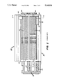
- FIG. 1 is a schematic illustration of an electrostatographic machine, such as an optical copier, including the development apparatus of the present invention
- FIG. 2 is a top view of a prior art development apparatus
- FIG. 3 is a schematic cross-sectional view of the apparatus of FIG. 2 taken along line X--X;
- FIG. 4 is a graphical illustration of the magnetic fields in the magnetic and non-magnetic field areas around the second or right side development roller of FIGS. 2 and 3;
- FIG. 5 is a top view of the development apparatus of the present invention.
- FIG. 6 is a schematic cross-sectional view of the development apparatus of FIG. 5 taken along line Y--Y;
- FIG. 7 is a graphical illustration of the magnetic fields in the magnetic and non-magnetic field areas around the second or right side development roller of FIGS. 5 and 6, and including the device of the present invention.
- an electrostatographic reproduction apparatus or machine such as an optical copier is shown generally as 10.
- the apparatus 10 includes an image-bearing member 11 which is an endless flexible belt which has a frontside image-bearing surface 12.
- the member 11 is shown as an endless flexible web trained about the series of rollers 13-16, it should be understood that an image bearing member in the form of a rigid drum can be used instead.
- the member 11 as shown is trained about a series of rollers 13-16 for movement in the direction, for example, of the arrow T1.
- One of such rollers, for example, the roller 13, can be a drive roller for repeatedly moving the member 11 sequentially through a series of process stages shown, for example, as AA, BB, CC and DD.
- the stage AA includes components such as a primary charger 20 or other charge depositing component (not shown).
- the image of an original can thus be formed electrostatically on the surface -2, for example, by charging the surface 12 using the primary charger 20, and then imagewise discharging portions of such surface using an electronic printhead 22 or the like, and/or an optical system as shown partially.
- a typical optical system includes a light source (not shown) that illuminates a document sheet. The light rays reflected from the document sheet can then be reflected by a mirror such as 24 through a lens 26, and onto the surface 12 for such optical imaging.
- Stage BB therefore includes a development apparatus, such as the development apparatus of the present invention, shown generally as 30.
- the development apparatus 30 of the present invention contains a two-component magnetic developer material D that is comprised of magnetizable stainless steel carrier particles, and of magnetic toner particles which include magnetic particles.
- Such magnetic developer material is disclosed for example in the afore-mentioned U.S. application Ser. No. 433,248 (incorporated here by reference), and is particularly suitable for developing magnetic characters for use on a magnetic ink character recognition (MICR) machine.
- MICR magnetic ink character recognition
- the toner particles in the developer material D transfer to the image-bearing surface 12, and there adhere to the electrostatically formed image thereon, thereby making the image visible.
- that portion of the image-bearing member 11 carrying the toner image thereon then moves to the stage CC.
- the stage CC includes an image transfer station 33 where the visible toner image on the surface 12 is transferred to a suitable receiver sheet, such as a sheet of paper, which is fed in registration to the station 33 along a sheet travel path. After such image transfer, the copy sheet then travels to a fusing station 35, as shown, where the toner image is permanently fused to the receiver sheet to form a hard copy. Meanwhile, the used portion of member Il, from which the toner image was transferred, moves on towards the initial stage AA to again begin another imaging cycle.
- a suitable receiver sheet such as a sheet of paper
- the cleaning apparatus 40 may, for example, be any conventional apparatus such as a brush, a roller, a blade or a magnetic brush cleaning apparatus which are well known in the art.
- the apparatus 30 of the present invention includes the device of the present invention for partially skiving magnetic developer material from a development roller, as well as other features that are basically similar to those in the prior art development apparatus 130 of FIGS. 2-4. Like numerals have therefore been used where appropriate to refer to such similar features.
- the development apparatus 30 of the present invention includes an elongate housing 42 and two development rollers 44, 46.
- the housing 42 has a first side compartment A and a second side compartment B.
- a first helical feed auger 50 is mounted for mixing and feeding magnetic developer material D from a front end 52 of the apparatus 30 back to the rear end 54 thereof.
- a similar auger 84 mounted in the second compartment B moves developer material from the second end 54 back to the first end 52.
- Means such as a paddle wheel 85 mounted in the first end 52 transfers developer material from the second compartment B to the first compartment A.
- the magnetic developer material D being handled in the apparatus 30 consists of needle- or acicular-shaped magnetizable stainless steel carrier particles, and of magnetic toner particles.
- the magnetic toner particles include particles of a binder resin, and particles of a magnetic material.
- the magnetic developer material D as such, possesses magnetic fields of its own which result in the formation of magnetic chains of the particles thereof.
- such developer material D, and/or replenishment toner particles therefor are added into a front portion 56 (FIG. 5) for subsequent movement and mixing.
- the development rollers 44, 46 are each provided with sets of magnets, for example SIN1 and S2N2-N5 of the roller 46, for magnetically attracting the magnetic developer material D onto the surface of each roller.
- each roller 44, 46 includes a non-magnetic rotatable outer shell 60, 62 respectively, and a stationary core 64, 66 respectively onto which the sets of magnets are assembled.
- the developer material D can thus be moved in the direction of the arrows 68, 70 when attracted onto the rotatable shells 60, 62 which are driven by imparting a drive to the gears 190, 192, respectively.
- the magnetic chains of the particles of the developer material D form standing bristle-like patterns when being moved through areas where there are magnets and magnetic fields. Such magnetic chains, however, collapse into a magnetic pile in areas where there are no magnets and hence no magnetic fields.
- the combined effect of the auger 50 and the rollers 44, 46 is to move the developer material D, in the form of a repeating band shown as H, side-to-side around the first compartment A, as well as from the front 52 to the back 54.
- the rollers 44, 46 carry the magnetic developer material D through development zones shown as T 1 , T 2 (FIG. 6) where latent images or characters 100 being carried on an image-bearing member 102 are developed with the magnetic toner particles in the material D.
- the magnetic toner particles used up in development must be replenished, and the flow of the developer material D from the end 52 to the end 54 within the housing 42 must be balanced.
- a device designated generally as 104 is provided in the development apparatus 30 for removing a desired partial amount of the magnetic developer material D from the development roller 46 . at the end 54, for recirculation back to the end 52.
- the device 104 must therefore be capable of breaking the magnetic chains of the magnetic developer material D which otherwise would ordinarily cause an all-or-nothing flow of the developer material D under or over a skiving edge such as 90 positioned adjacent the development roller 46 as in the prior art apparatus 130 of FIGS. 2-4.
- the device 104 of the present invention includes a first magnet S4, a second magnet N6 and a skiving plate member 106 located near the periphery of the rotating shell 62.
- the first magnet S4 has a first polarity, for example an S-polarity. It is mounted to the stationary core 66 of the development roller 46 and generates a first magnetic field 108 (FIG. 7) just downstream of the development zone T 2 , as shown relative to the direction of movement of the shell 62.
- the magnetic field 108 causes the magnetic chains of magnetic particles of the magnetic developer material D to stand as bristles on a first end thereof on the outside surface of the shell 62 of the roller 46.
- the second magnet N6 has a second polarity that is opposite to the first polarity of the first magnet S4, for example, an N-polarity.
- the second magnet N6 is also mounted to the stationary core 66 of the development roller 46 for generating a second magnetic field shown as 110 thereabout. Being opposite to the first magnetic field 108, the second magnetic field 110 will cause the magnetic bristles of particles of the development material D to tend to stand on a second and opposite end thereof on the shell 62. As shown, the first magnetic field 108 is made stronger than the second field 110.
- the first and second magnets S4 and N6 are mounted as such to the core 66 such that the second magnetic field 110 is generated immediately downstream of the first field 108 relative to the moving shell 62. The positioning of the magnetic fields 108, 110 in this manner tends to cause a flipping of the magnetic bristles from standing on the first end (within the first field 108) to standing on the second end thereof (within the second field 110).
- the device 104 further includes the skiving plate member 106 which has a skiving edge 112.
- the plate member 106 is mounted such that the edge 112 is positioned approximately between the first and second magnetic fields 108, 110, and so as to be spaced a small adjustable gap 114 from the outside surface or periphery of the rotating shell 62 of the roller 46.
- the gap 114 should be such that the edge 112 interferes with, and breaks or severs the magnetic bristles as such bristles are flipping from standing on a first end to standing on a second end in moving from the first field 108 to the second field 110.
- the magnetic forces which cause such flipping when combined with mechanical forces by the moving shell 62 and the skiving edge 112, are sufficient to break or sever the magnetic chains which would otherwise bridge the gap 114.
- Such breaking or severing of the bristles between the magnetic fields causes a first and desired amount of the magnetic developer material D to remain on the outside surface of the development roller 46 therefore passing through the gap 114 and hence under the edge 112 for retention and continued movement by the rollers 46, 44 in the first compartment A.
- Such breaking or severing also causes a second and desired partial amount of the magnetic developer material D to be removed from the roller 46 by passing over the edge 112. Such a second amount is then directed gravitationally by the plate member 106 away from the development roller 46.
- the plate member 106 is mounted within an opening 116 in the wall 49 which divides the first and second compartments A, B. As such, the second amount of developer material passing over the plate member 106 is directed through the opening 116 into the second compartment B for return by the auger 84 from the rear end 54 to the front end 52 of the apparatus 30.
- the device 104 is appropriately located towards the very end of the second or rear end 54 of the apparatus 30. Such location allows undisturbed image or character development between the ends, as well as ensures recirculation of only developer material depleted by such development. The amount of such depleted material recirculated depends in part on the size of the gap 114, therefore the plate member 106 is made adjustable so as to enable adjustment of the gap 114.
- the plate member 106 and the second magnet N6 as shown are each shorter than the development roller 46.
- the plate 106 and second magnet N6 may be equal in length, and preferable such length should be sufficient to span the width of the developer material flow band H.
- the first magnet S4 is longitudinally as long as the development roller 46.
- the development apparatus 30 of the present invention can handle and recirculate the magnetic development material D.
- the device 104 including the first and second magnets S4, and N6 located as specified operate with the skiving plate member 106 to flip and break or sever magnetic bristles of the magnetic chains of such developer material D.
- magnetic chains are prevented from bridging the gap 114, and the device 104 can therefore effectively remove a desired partial amount of such developer material from the development roller 46 for recirculation therein.
- Such partial removal and recirculation allows for continued quality image development by the apparatus 30.
Landscapes
- Physics & Mathematics (AREA)
- General Physics & Mathematics (AREA)
- Dry Development In Electrophotography (AREA)
- Magnetic Brush Developing In Electrophotography (AREA)
Abstract
Description
Claims (12)
Priority Applications (1)
| Application Number | Priority Date | Filing Date | Title |
|---|---|---|---|
| US07/631,124 US5140936A (en) | 1990-12-20 | 1990-12-20 | Development apparatus having means for partially skiving magnetic developer |
Applications Claiming Priority (1)
| Application Number | Priority Date | Filing Date | Title |
|---|---|---|---|
| US07/631,124 US5140936A (en) | 1990-12-20 | 1990-12-20 | Development apparatus having means for partially skiving magnetic developer |
Publications (1)
| Publication Number | Publication Date |
|---|---|
| US5140936A true US5140936A (en) | 1992-08-25 |
Family
ID=24529865
Family Applications (1)
| Application Number | Title | Priority Date | Filing Date |
|---|---|---|---|
| US07/631,124 Expired - Lifetime US5140936A (en) | 1990-12-20 | 1990-12-20 | Development apparatus having means for partially skiving magnetic developer |
Country Status (1)
| Country | Link |
|---|---|
| US (1) | US5140936A (en) |
Cited By (5)
| Publication number | Priority date | Publication date | Assignee | Title |
|---|---|---|---|---|
| US5489975A (en) * | 1993-05-20 | 1996-02-06 | Eastman Kodak Company | Image forming method and apparatus |
| US20050260020A1 (en) * | 2004-05-21 | 2005-11-24 | Eastman Kodak Company | Skiving device and methods of use |
| US20060000338A1 (en) * | 2004-05-21 | 2006-01-05 | Eastman Kodak Company | Roller and methods of use |
| CN100430835C (en) * | 2002-04-26 | 2008-11-05 | 佳能株式会社 | Developing apparatus |
| US20080279596A1 (en) * | 2007-05-09 | 2008-11-13 | Xerox Corporation | Low graininess printing and micr printing with scmb and ea-scmb systems |
Citations (5)
| Publication number | Priority date | Publication date | Assignee | Title |
|---|---|---|---|---|
| US3543720A (en) * | 1968-02-29 | 1970-12-01 | Eastman Kodak Co | Apparatus for development of electrostatic images |
| US4101211A (en) * | 1976-07-12 | 1978-07-18 | Eastman Kodak Company | Magnetic curtain seal for development apparatus |
| US4800412A (en) * | 1985-03-22 | 1989-01-24 | Minolta Camera Kabushiki Kaisha | Apparatus for developing electrostatic latent images |
| US4851872A (en) * | 1986-05-15 | 1989-07-25 | Minolta Camera Kabushiki Kaisha | Developing device with developer sleeve facilitating developer supply adjustment by bristle height regulating member |
| US5047807A (en) * | 1990-10-15 | 1991-09-10 | Eastman Kodak Company | Development apparatus having a plate scavenging device |
-
1990
- 1990-12-20 US US07/631,124 patent/US5140936A/en not_active Expired - Lifetime
Patent Citations (5)
| Publication number | Priority date | Publication date | Assignee | Title |
|---|---|---|---|---|
| US3543720A (en) * | 1968-02-29 | 1970-12-01 | Eastman Kodak Co | Apparatus for development of electrostatic images |
| US4101211A (en) * | 1976-07-12 | 1978-07-18 | Eastman Kodak Company | Magnetic curtain seal for development apparatus |
| US4800412A (en) * | 1985-03-22 | 1989-01-24 | Minolta Camera Kabushiki Kaisha | Apparatus for developing electrostatic latent images |
| US4851872A (en) * | 1986-05-15 | 1989-07-25 | Minolta Camera Kabushiki Kaisha | Developing device with developer sleeve facilitating developer supply adjustment by bristle height regulating member |
| US5047807A (en) * | 1990-10-15 | 1991-09-10 | Eastman Kodak Company | Development apparatus having a plate scavenging device |
Cited By (7)
| Publication number | Priority date | Publication date | Assignee | Title |
|---|---|---|---|---|
| US5489975A (en) * | 1993-05-20 | 1996-02-06 | Eastman Kodak Company | Image forming method and apparatus |
| CN100430835C (en) * | 2002-04-26 | 2008-11-05 | 佳能株式会社 | Developing apparatus |
| US20050260020A1 (en) * | 2004-05-21 | 2005-11-24 | Eastman Kodak Company | Skiving device and methods of use |
| US20060000338A1 (en) * | 2004-05-21 | 2006-01-05 | Eastman Kodak Company | Roller and methods of use |
| US7024153B2 (en) * | 2004-05-21 | 2006-04-04 | Eastman Kodak Company | Skiving device and methods of use |
| US7685692B2 (en) | 2004-05-21 | 2010-03-30 | Industrial Technology Research Institute | Process for removing material from a substrate |
| US20080279596A1 (en) * | 2007-05-09 | 2008-11-13 | Xerox Corporation | Low graininess printing and micr printing with scmb and ea-scmb systems |
Similar Documents
| Publication | Publication Date | Title |
|---|---|---|
| US5010368A (en) | Magnetic transport roll for supplying toner or carrier and toner to a donor and magnetic developer roll respectively | |
| US4349270A (en) | Developer removing device for copying apparatus | |
| US5204721A (en) | Developer auger for use in an electrophotographic printing machine | |
| US4601569A (en) | Apparatus for cleaning a photoconductor | |
| US5047807A (en) | Development apparatus having a plate scavenging device | |
| US3920329A (en) | Background removal apparatus | |
| GB1581156A (en) | Electrophotographic cleaning apparatus | |
| EP0083990B1 (en) | Self-cleaning xerographic apparatus | |
| US3965862A (en) | Xerographic development system | |
| US4357097A (en) | Electrostatic recording apparatus having a toner recovering device | |
| US5184194A (en) | Carrier particle scavenging device | |
| EP0024822A1 (en) | Apparatus for developing electrostatic latent images | |
| US5140936A (en) | Development apparatus having means for partially skiving magnetic developer | |
| CN100511015C (en) | Carrier particle pickup device and electrostatic imaging printer | |
| JP2518869B2 (en) | Development device | |
| US5080038A (en) | Extended NIP development apparatus having a transport assist magnet | |
| US5282008A (en) | Magnetic roller cleaning apparatus | |
| CA1079954A (en) | Toner reclaim conveyor | |
| EP0036290A1 (en) | Apparatus for cleaning particles from a surface | |
| US5181075A (en) | Development apparatus having an extended development nip | |
| US4771311A (en) | Development apparatus | |
| US4982238A (en) | Developer material mixing apparatus for a development unit | |
| US4087168A (en) | Charging system for electrostatic reproduction machine | |
| US5363183A (en) | Copying machine with device for removing carrier beads from the photoconductive surface | |
| US3648657A (en) | Electrostatic image development apparatus |
Legal Events
| Date | Code | Title | Description |
|---|---|---|---|
| AS | Assignment |
Owner name: EASTMAN KODAK COMPANY, ROCHESTER, NY A CORP. OF NJ Free format text: ASSIGNMENT OF ASSIGNORS INTEREST.;ASSIGNORS:STRONG, DOUGLAS B.;CYRANA, EDWARD M.;HILBERT, THOMAS K.;REEL/FRAME:005547/0939 Effective date: 19901214 |
|
| FEPP | Fee payment procedure |
Free format text: PAYOR NUMBER ASSIGNED (ORIGINAL EVENT CODE: ASPN); ENTITY STATUS OF PATENT OWNER: LARGE ENTITY |
|
| STCF | Information on status: patent grant |
Free format text: PATENTED CASE |
|
| FEPP | Fee payment procedure |
Free format text: PAYER NUMBER DE-ASSIGNED (ORIGINAL EVENT CODE: RMPN); ENTITY STATUS OF PATENT OWNER: LARGE ENTITY Free format text: PAYOR NUMBER ASSIGNED (ORIGINAL EVENT CODE: ASPN); ENTITY STATUS OF PATENT OWNER: LARGE ENTITY |
|
| FPAY | Fee payment |
Year of fee payment: 4 |
|
| FEPP | Fee payment procedure |
Free format text: PAYER NUMBER DE-ASSIGNED (ORIGINAL EVENT CODE: RMPN); ENTITY STATUS OF PATENT OWNER: LARGE ENTITY Free format text: PAYOR NUMBER ASSIGNED (ORIGINAL EVENT CODE: ASPN); ENTITY STATUS OF PATENT OWNER: LARGE ENTITY |
|
| FPAY | Fee payment |
Year of fee payment: 8 |
|
| AS | Assignment |
Owner name: NEXPRESS SOLUTIONS LLC, NEW YORK Free format text: ASSIGNMENT OF ASSIGNORS INTEREST;ASSIGNOR:EASTMAN KODAK COMPANY;REEL/FRAME:012036/0959 Effective date: 20000717 |
|
| FPAY | Fee payment |
Year of fee payment: 12 |
|
| AS | Assignment |
Owner name: EASTMAN KODAK COMPANY, NEW YORK Free format text: ASSIGNMENT OF ASSIGNORS INTEREST;ASSIGNOR:NEXPRESS SOLUTIONS, INC. (FORMERLY NEXPRESS SOLUTIONS LLC);REEL/FRAME:015928/0176 Effective date: 20040909 |
|
| FEPP | Fee payment procedure |
Free format text: PAYER NUMBER DE-ASSIGNED (ORIGINAL EVENT CODE: RMPN); ENTITY STATUS OF PATENT OWNER: LARGE ENTITY Free format text: PAYOR NUMBER ASSIGNED (ORIGINAL EVENT CODE: ASPN); ENTITY STATUS OF PATENT OWNER: LARGE ENTITY |