US5140134A - Nestable stackable heated bowl with thermostatically controlled electric heating element - Google Patents
Nestable stackable heated bowl with thermostatically controlled electric heating element Download PDFInfo
- Publication number
- US5140134A US5140134A US07/565,469 US56546990A US5140134A US 5140134 A US5140134 A US 5140134A US 56546990 A US56546990 A US 56546990A US 5140134 A US5140134 A US 5140134A
- Authority
- US
- United States
- Prior art keywords
- wall
- bowl
- heating element
- nestable
- cord
- Prior art date
- Legal status (The legal status is an assumption and is not a legal conclusion. Google has not performed a legal analysis and makes no representation as to the accuracy of the status listed.)
- Expired - Lifetime
Links
Images

Classifications
-
- A—HUMAN NECESSITIES
- A01—AGRICULTURE; FORESTRY; ANIMAL HUSBANDRY; HUNTING; TRAPPING; FISHING
- A01K—ANIMAL HUSBANDRY; CARE OF BIRDS, FISHES, INSECTS; FISHING; REARING OR BREEDING ANIMALS, NOT OTHERWISE PROVIDED FOR; NEW BREEDS OF ANIMALS
- A01K7/00—Watering equipment for stock or game
- A01K7/02—Automatic devices ; Medication dispensers
- A01K7/027—Drinking equipment with water heaters, coolers or means for preventing freezing
-
- A—HUMAN NECESSITIES
- A01—AGRICULTURE; FORESTRY; ANIMAL HUSBANDRY; HUNTING; TRAPPING; FISHING
- A01K—ANIMAL HUSBANDRY; CARE OF BIRDS, FISHES, INSECTS; FISHING; REARING OR BREEDING ANIMALS, NOT OTHERWISE PROVIDED FOR; NEW BREEDS OF ANIMALS
- A01K5/00—Feeding devices for stock or game ; Feeding wagons; Feeding stacks
- A01K5/01—Feed troughs; Feed pails
- A01K5/0114—Pet food dispensers; Pet food trays
-
- A—HUMAN NECESSITIES
- A47—FURNITURE; DOMESTIC ARTICLES OR APPLIANCES; COFFEE MILLS; SPICE MILLS; SUCTION CLEANERS IN GENERAL
- A47J—KITCHEN EQUIPMENT; COFFEE MILLS; SPICE MILLS; APPARATUS FOR MAKING BEVERAGES
- A47J27/00—Cooking-vessels
- A47J27/004—Cooking-vessels with integral electrical heating means
-
- A—HUMAN NECESSITIES
- A47—FURNITURE; DOMESTIC ARTICLES OR APPLIANCES; COFFEE MILLS; SPICE MILLS; SUCTION CLEANERS IN GENERAL
- A47J—KITCHEN EQUIPMENT; COFFEE MILLS; SPICE MILLS; APPARATUS FOR MAKING BEVERAGES
- A47J36/00—Parts, details or accessories of cooking-vessels
- A47J36/24—Warming devices
- A47J36/2483—Warming devices with electrical heating means
-
- H—ELECTRICITY
- H05—ELECTRIC TECHNIQUES NOT OTHERWISE PROVIDED FOR
- H05B—ELECTRIC HEATING; ELECTRIC LIGHT SOURCES NOT OTHERWISE PROVIDED FOR; CIRCUIT ARRANGEMENTS FOR ELECTRIC LIGHT SOURCES, IN GENERAL
- H05B3/00—Ohmic-resistance heating
- H05B3/20—Heating elements having extended surface area substantially in a two-dimensional plane, e.g. plate-heater
- H05B3/34—Heating elements having extended surface area substantially in a two-dimensional plane, e.g. plate-heater flexible, e.g. heating nets or webs
- H05B3/36—Heating elements having extended surface area substantially in a two-dimensional plane, e.g. plate-heater flexible, e.g. heating nets or webs heating conductor embedded in insulating material
-
- H—ELECTRICITY
- H05—ELECTRIC TECHNIQUES NOT OTHERWISE PROVIDED FOR
- H05B—ELECTRIC HEATING; ELECTRIC LIGHT SOURCES NOT OTHERWISE PROVIDED FOR; CIRCUIT ARRANGEMENTS FOR ELECTRIC LIGHT SOURCES, IN GENERAL
- H05B2203/00—Aspects relating to Ohmic resistive heating covered by group H05B3/00
- H05B2203/002—Heaters using a particular layout for the resistive material or resistive elements
- H05B2203/005—Heaters using a particular layout for the resistive material or resistive elements using multiple resistive elements or resistive zones isolated from each other
-
- H—ELECTRICITY
- H05—ELECTRIC TECHNIQUES NOT OTHERWISE PROVIDED FOR
- H05B—ELECTRIC HEATING; ELECTRIC LIGHT SOURCES NOT OTHERWISE PROVIDED FOR; CIRCUIT ARRANGEMENTS FOR ELECTRIC LIGHT SOURCES, IN GENERAL
- H05B2203/00—Aspects relating to Ohmic resistive heating covered by group H05B3/00
- H05B2203/013—Heaters using resistive films or coatings
-
- H—ELECTRICITY
- H05—ELECTRIC TECHNIQUES NOT OTHERWISE PROVIDED FOR
- H05B—ELECTRIC HEATING; ELECTRIC LIGHT SOURCES NOT OTHERWISE PROVIDED FOR; CIRCUIT ARRANGEMENTS FOR ELECTRIC LIGHT SOURCES, IN GENERAL
- H05B2203/00—Aspects relating to Ohmic resistive heating covered by group H05B3/00
- H05B2203/017—Manufacturing methods or apparatus for heaters
-
- H—ELECTRICITY
- H05—ELECTRIC TECHNIQUES NOT OTHERWISE PROVIDED FOR
- H05B—ELECTRIC HEATING; ELECTRIC LIGHT SOURCES NOT OTHERWISE PROVIDED FOR; CIRCUIT ARRANGEMENTS FOR ELECTRIC LIGHT SOURCES, IN GENERAL
- H05B2203/00—Aspects relating to Ohmic resistive heating covered by group H05B3/00
- H05B2203/021—Heaters specially adapted for heating liquids
Definitions
- the present invention relates generally to a heated bowl designed to prevent liquids such as water from freezing when it is placed outside in cold, below freezing weather, and more particularly to a heated pet bowl that permits the bowls to be stacked and nested upon one another in a stable fashion to permit the bowls to be placed on public display and/or to be stacked in a small amount of space in the home or in the store.
- Heated bowls particularly bowls designed to keep water from freezing in below freezing temperature so that a pet will have access to water or food at all times were known prior to the present invention.
- the prior art pet bowls however, all had a common undesirable feature; that is, all of the prior art pet bowls known to the inventors were not nestable in an interengaging compact fashion.
- the prior art heated pet bowls are manufactured by placing a heating element in the bottom of the bowl and enclosing the entire bottom of the pet bowl. By enclosing the entire bottom of the bowl there is produced a structure that does not permit the bowls to be conveniently nested or for the power cord to be conveniently stored in the bottom portion of the bowl.
- the improved device encloses a heating element in a thin cavity beneath the bowl. Rather than totally enclosing the entire area under the bowl, the improved device leaves open the space beneath the thin cavity and behind and underneath the sides of the bowl. In the center portion of this open space, the power cord of the device may be neatly coiled adjacent to the heating element cavity and around a centrally positioned thermostat mechanism for storage during shipment. In the circumferential portion of this open space, a second bowl will fit neatly, thus allowing for the nestable stacking of a plurality of such bowls.
- Another object of the present invention is to provide a heated bowl which provides space for storing the cord used to provide electric power to the bowl in a space beneath the bottom of the heated inverted bowl, while still permitting the heated bowls to be nested one upon another in a manner that minimizes storage space during.
- Yet another object of the present invention is to provide an improved nestable heated bowl for pet food or the like which interengages with another like bowl to provide a stable and compact stack.
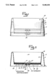
- FIG. 1 is a side elevational view showing two superimposed heated bowls in accordance of the present invention to show the ability of these bowls to be nested one upon another;
- FIG. 2 is a side sectional view of one of the nestable heated bowls shown in FIG. 1;
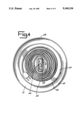
- FIG. 3 is a bottom view of the bowls illustrated in FIGS. 1 and 2 eliminating an illustration of the cord used to provide electricity to the heating element;
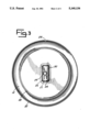
- FIG. 4 is a bottom view of one of the nestable heated bowls illustrated in FIG. 1, showing the positioning of an electric power cord on the bottom portion of the heated bowl to permit the bowl to be nested while still providing a space for storage of the electric cord;
- FIG. 5 is a plan view of a preferred heating element used in the bowls.
- Bowl 2 which is identical to bowl 4, is illustrated in greater detail in FIG. 2.
- Bowl 2 is formed from a molded plastic by means well known to those trained in the art.
- the molded bowl 2 is provided with an outer wall 6, an inner wall 8 and an interior bottom 10.
- the bowl 2 is circular, as shown, for ease of cleaning, though other shapes, such as square, are possible, as will be apparent to persons trained in the art.
- Inner wall 8 and bottom 10 cooperate to define a hollow cavity 14 for containing liquid, or food, within the bowl structure 2.
- outer wall 6 and inner wall 8 taper upwardly and are spaced apart a distance sufficient to define a space 12 between outer wall 6 and inner wall 8.
- Walls 6 and 8 meet at the top to provide a curved or rounded bowl edge 26.
- the bottom edge 32 of outer wall 6 defines an open lower end of the bowl.
- the bowl edge 26 of lower dish 4 extends substantially upwards within space 12 of upper dish 2 (See FIG. 1).
- the bowls of the present invention are substantially more stable when stacked upon each other than the prior art bowls because of the insertion of edge 26 of one bowl into the space 12 of a second bowl.
- the bottom of the bowl is enclosed at bottom edge 32. As a result, the bowls cannot be stacked in an interengaging manner, as with the present invention, and there is no room to store an electrical cord within the base of the bowl.
- stackable heated bowl 2 is provided with a heating element cavity 16 between the bottom 10 of hollow cavity 14 and bottom base 20. Specifically, bottom 10 and base 20 cooperate to provide a hollow cavity 16.
- a conventional flat resistive ink heating element 18 as illustrated in FIG. 5 is placed in this cavity 16 in heat transfer relationship with the bottom 10. Normally the heating element 18 is bonded by an adhesive or otherwise affixed to the bottom 10.
- Foam insert 19 provides insulation for cavity 16 and helps the transfer of heat from heating element 18 to the bottom 10 of the bowl.
- Heating element 18 provides uniform heating with almost full contact between the flat bottom 10 of the bowl and the flat top surface of heater element 18. This arrangement maximizes heat transfer to bottom 10 of the bowl.
- Element 18 is preferably a thin resistive ink element of the type manufactured by Flexwatt Corporation, 2380 Cranberry Highway, West Wareham, Mass. 02756. As illustrated in FIG. 5, heating element 18 is a thin flexible sheet 40 having a resistive ink heating elements 42 printed thereon. Electricity is provided to heating elements 42 through electrical leads 44 and junction 46. Leads 44 in turn are connected to thermostat 24.
- a cavity wall 25 defining a thermostat cavity 22 adapted to receive a conventional thermostat 24.
- a thermal enhancing compound 23 such as a heat sink compound or a thermally conductive pad for increasing thermal conductivity between the bottom of the bowl and the thermostat 24.
- the temperature of the contents of the liquids or solids placed within cavity 14 is monitored by thermostat 24 which, in turn, controls the amount of electricity to and thus the amount of heat transmitted by heating elements 18 to the contents of cavity 14.
- the bottom edge 32 of stackable heated bowl 2 is spaced outwardly from the bottom base 20 of heating element cavity 16 to permit the accommodation of a conventional electric cord.
- a conventional electric cord 30 is connected to thermostat 24 in thermostat cavity 22.
- the flexible electric cord 30 extends from the cavity 22 and is then looped around thermostat cavity 22 and placed on top of bottom base 20 when the bowl is inverted.
- the cord 30 then occupies the space 36 between the bottom edge 32 of the bowl and bottom base 20.
- the cord 30 is wound or looped so as to lie in a generally horizontal plane.
- the cord 30 should not extend beyond the perimeter or edge 38 of bottom base 20. If the cord extends beyond edge 38 it could interfere with the placement of top bowl edge 26 into the space 12 between walls 6 and 8 and thus interfere with the compact interengaging nesting of the bowls.
- the cord 30 is placed against a wall of the thermostat cavity 22, as best seen in FIG. 4.
- the cord 30 slopes upwardly and outwardly from the bottom of the cavity 22.
- the leads 34 from cord 30 are secured to thermostat 24 and to the heating element 18 in a conventional fashion.
- the cavity 22 is filled with an epoxy or other potting compound 27 to secure the leads 34 from the end of the cord 30 in place and to protect against moisture.
- the flexible electrical cord 30 is uncoiled from the bottom wall of the inverted bowl and placed through notch or opening 28 in outer wall 6. This permits the stackable heated bowl 2 to be placed right side up on a flat surface during use.
Abstract
Description
Claims (8)
Priority Applications (3)
| Application Number | Priority Date | Filing Date | Title |
|---|---|---|---|
| US07/565,469 US5140134A (en) | 1990-08-10 | 1990-08-10 | Nestable stackable heated bowl with thermostatically controlled electric heating element |
| CA002035731A CA2035731C (en) | 1990-08-10 | 1991-02-05 | Nestable stackable heated bowl with thermostatically controlled electric heating element |
| US07/929,885 US5345063A (en) | 1990-08-10 | 1992-08-11 | Nestable stackable heated bowl with removable thermostatically controlled electric heating element |
Applications Claiming Priority (1)
| Application Number | Priority Date | Filing Date | Title |
|---|---|---|---|
| US07/565,469 US5140134A (en) | 1990-08-10 | 1990-08-10 | Nestable stackable heated bowl with thermostatically controlled electric heating element |
Related Child Applications (1)
| Application Number | Title | Priority Date | Filing Date |
|---|---|---|---|
| US07/929,885 Continuation-In-Part US5345063A (en) | 1990-08-10 | 1992-08-11 | Nestable stackable heated bowl with removable thermostatically controlled electric heating element |
Publications (1)
| Publication Number | Publication Date |
|---|---|
| US5140134A true US5140134A (en) | 1992-08-18 |
Family
ID=24258750
Family Applications (2)
| Application Number | Title | Priority Date | Filing Date |
|---|---|---|---|
| US07/565,469 Expired - Lifetime US5140134A (en) | 1990-08-10 | 1990-08-10 | Nestable stackable heated bowl with thermostatically controlled electric heating element |
| US07/929,885 Expired - Lifetime US5345063A (en) | 1990-08-10 | 1992-08-11 | Nestable stackable heated bowl with removable thermostatically controlled electric heating element |
Family Applications After (1)
| Application Number | Title | Priority Date | Filing Date |
|---|---|---|---|
| US07/929,885 Expired - Lifetime US5345063A (en) | 1990-08-10 | 1992-08-11 | Nestable stackable heated bowl with removable thermostatically controlled electric heating element |
Country Status (2)
| Country | Link |
|---|---|
| US (2) | US5140134A (en) |
| CA (1) | CA2035731C (en) |
Cited By (37)
| Publication number | Priority date | Publication date | Assignee | Title |
|---|---|---|---|---|
| US5231953A (en) * | 1992-11-30 | 1993-08-03 | Garrett David S | Dog dish apparatus |
| US5345063A (en) * | 1990-08-10 | 1994-09-06 | Allied Precision Industries, Inc. | Nestable stackable heated bowl with removable thermostatically controlled electric heating element |
| US5452683A (en) * | 1992-11-04 | 1995-09-26 | Dan J. Schleppe | Animal drinking water supply apparatus |
| DE29714770U1 (en) * | 1997-08-18 | 1997-11-27 | Rieker Elektronik | Heating device for an electrical device and electrical device for heating a liquid |
| GB2321380A (en) * | 1997-01-22 | 1998-07-29 | Alfred Edward Cackett | Internally heated birdbath |
| US6180925B1 (en) * | 1997-11-28 | 2001-01-30 | U.S. Philips Corporation | Heating element with regions of high/low density |
| US6363886B1 (en) * | 1999-07-20 | 2002-04-02 | Christine J. Statton | Heated/cooled live-food bird feeder |
| US6469281B1 (en) | 2001-04-12 | 2002-10-22 | Allied Precision Industries, Inc. | Heated watering bucket |
| US20060144588A1 (en) * | 2004-10-22 | 2006-07-06 | Core Laboratories Lp | Method for determining tracer concentration in oil and gas production fluids |
| US20060237429A1 (en) * | 2005-03-29 | 2006-10-26 | Reusche Thomas K | Bucket with access door |
| US20070175886A1 (en) * | 2006-02-02 | 2007-08-02 | Hamilton Beach/Proctor-Silex, Inc. | Slow cooker |
| US20090001231A1 (en) * | 2007-06-29 | 2009-01-01 | Joseph Casanova | Nesting Elevated Pet Feeder Stands |
| US20100313815A1 (en) * | 2007-11-14 | 2010-12-16 | Yasushi Maeda | Water drinking container for animals |
| US8146535B1 (en) | 2008-01-07 | 2012-04-03 | Neumann Edward C | Thermally controlled drinking water system for animals |
| US20130319995A1 (en) * | 2012-05-30 | 2013-12-05 | Bsh Home Appliances Corporation | Household appliance having a warming drawer with a thermally conductive layer |
| US20130323663A1 (en) * | 2012-05-30 | 2013-12-05 | Bsh Home Appliances Corporation | Household appliance having a deployable warming drawer module |
| US20130323662A1 (en) * | 2012-05-30 | 2013-12-05 | Bsh Home Appliances Corporation | Household appliance having a thermostat retainer for a thermostat of a warming drawer |
| JP2016042795A (en) * | 2014-08-20 | 2016-04-04 | ジェックス株式会社 | Waterer for pet |
| JP2016182260A (en) * | 2015-03-26 | 2016-10-20 | ジェックス株式会社 | Heat retention storage for pet food |
| US20190225054A1 (en) * | 2018-01-23 | 2019-07-25 | Borgwarner Ludwigsburg Gmbh | Heating device and method for producing a heating rod |
| CH715019A1 (en) * | 2018-05-24 | 2019-11-29 | Jochen Ganz Dr | Cooking vessel and cooking vessel system. |
| US10829259B2 (en) | 2017-03-29 | 2020-11-10 | Mars, Incorporated | Device and method for dispensing product from a flexible package |
| US11154034B2 (en) | 2018-09-19 | 2021-10-26 | Lg Electronics Inc. | Liquid dispenser having sensors |
| US11160250B2 (en) | 2018-09-19 | 2021-11-02 | Lg Electronics Inc. | Liquid dispenser for animals |
| US11191252B2 (en) * | 2018-09-19 | 2021-12-07 | Lg Electronics Inc. | Liquid dispenser for animals |
| US20220201973A1 (en) * | 2020-12-24 | 2022-06-30 | Amy Kim | Portable pet food bowl assembly |
| US11527906B2 (en) | 2018-09-19 | 2022-12-13 | Lg Electronics Inc. | Liquid dispenser for animals |
| US11565202B2 (en) | 2018-09-19 | 2023-01-31 | Lg Electronics Inc. | Liquid dispenser for animals |
| US11590438B2 (en) | 2018-09-19 | 2023-02-28 | Lg Electronics Inc. | Liquid dispenser for animals |
| US11596127B2 (en) | 2018-09-19 | 2023-03-07 | Lg Electronics Inc. | Liquid dispenser for animals |
| US11653627B2 (en) | 2018-09-19 | 2023-05-23 | Lg Electronics Inc. | Liquid dispenser for animals |
| US11659812B2 (en) | 2018-09-19 | 2023-05-30 | Lg Electronics Inc. | Liquid dispenser for animals |
| US11659813B2 (en) | 2018-09-19 | 2023-05-30 | Lg Electronics Inc. | Liquid dispenser for animals |
| US11771058B2 (en) | 2018-09-19 | 2023-10-03 | Lg Electronics Inc. | Liquid dispenser for animals |
| US11793160B2 (en) | 2018-09-19 | 2023-10-24 | Lg Electronics Inc. | Liquid dispenser for animals |
| US20230404027A1 (en) * | 2022-06-17 | 2023-12-21 | Sumpet Technology (Qingdao) Co. Ltd. | Pet feeding bowl assembly |
| US11871732B2 (en) | 2018-09-19 | 2024-01-16 | Lg Electronics Inc. | Liquid dispenser for animals |
Families Citing this family (37)
| Publication number | Priority date | Publication date | Assignee | Title |
|---|---|---|---|---|
| GB2294187A (en) * | 1994-10-14 | 1996-04-17 | Philips Electronics Nv | Thermal control in a liquid heater |
| US6091058A (en) * | 1995-04-26 | 2000-07-18 | O.R. Solutions, Inc. | Thermal treatment system and method for maintaining integrity and ensuring sterility of surgical drapes used with surgical equipment |
| US6009238A (en) * | 1997-03-18 | 1999-12-28 | The West Bend Company | Water distiller with improved automatic shutoff feature |
| JPH1146752A (en) * | 1997-07-31 | 1999-02-23 | Masuda Rika Kogyo Kk | Anaerobic incubator |
| US5908008A (en) * | 1997-11-17 | 1999-06-01 | Sensabaugh; Glenn C. | Recirculating watering system |
| ES2138546B1 (en) * | 1997-11-26 | 2000-09-16 | Byse Electrodomesticos S A | HEATING SYSTEM FOR COOKING. |
| GB9819091D0 (en) * | 1998-09-03 | 1998-10-28 | Goodwin Barry N | Base for a heating vessel and a method of manufacturing thereof |
| US6167945B1 (en) | 1999-08-23 | 2001-01-02 | Refrigeration Research, Inc. | Non-freezing watering dish for animals |
| US6184500B1 (en) | 2000-03-10 | 2001-02-06 | Homedics, Inc. | Paraffin bath |
| US6860271B2 (en) * | 2000-05-17 | 2005-03-01 | O.R. Solutions, Inc. | Thermal treatment system and method for controlling the system to thermally treat sterile surgical liquid |
| US6371121B1 (en) * | 2000-05-17 | 2002-04-16 | O.R. Solutions, Inc. | Remote controlled thermal treatment system and method for controlling the system remotely to thermally treat sterile surgical liquid |
| US7959860B2 (en) * | 2001-10-22 | 2011-06-14 | Faries Jr Durward I | System and method of detecting fluid and leaks in thermal treatment system basins |
| US6810881B2 (en) | 2001-10-22 | 2004-11-02 | O.R. Solutions, Inc. | Medical solution thermal treatment system and method of controlling system operation in accordance with detection of solution and leaks in surgical drape containers |
| US7418966B2 (en) * | 2001-10-22 | 2008-09-02 | O. R. Solutions, Inc. | Surgical drape and method of detecting fluid and leaks in thermal treatment system basins |
| US7347210B2 (en) * | 2001-10-22 | 2008-03-25 | O.R. Solutions, Inc. | Surgical drape with conductor and method of detecting fluid and leaks in thermal treatment system Basins |
| US7854230B2 (en) | 2001-10-22 | 2010-12-21 | O.R. Solutions, Inc. | Heated medical instrument stand with surgical drape and method of detecting fluid and leaks in the stand tray |
| US6722313B2 (en) * | 2001-11-27 | 2004-04-20 | Thomas William Wenstrand | All weather animal drinker |
| US6831256B2 (en) * | 2002-10-15 | 2004-12-14 | Omniteam, Inc. | Super-thin restaurant griddle |
| US20050056226A1 (en) * | 2003-09-12 | 2005-03-17 | Ruggiero Michael Joseph | Thermally assisted pet dish |
| US20050247169A1 (en) * | 2003-11-26 | 2005-11-10 | Faries Durward I Jr | Fastening system and method of fastening objects with enhanced security |
| US7350373B1 (en) | 2003-12-23 | 2008-04-01 | O.R. Solutions, Inc. | Surgical disk drape and method of dislodging surgical slush within thermal treatment system basins |
| DE202004002665U1 (en) * | 2004-02-20 | 2004-09-02 | Suevia Haiges Gmbh | Impregnation device with a heating device |
| US7671302B1 (en) | 2004-03-23 | 2010-03-02 | O. R. Solutions, Inc. | Thermal treatment system instrument rack and method of selectively thermally treating medical instrument portions |
| US7728262B1 (en) * | 2004-03-23 | 2010-06-01 | O.R. Solutions, Inc. | Thermal treatment system instrument rack and method of selectively thermally treating medical instrument portions |
| US20060011528A1 (en) * | 2004-09-13 | 2006-01-19 | Jonathan Ireland | Animal water tub |
| ATE355784T1 (en) * | 2005-01-12 | 2007-03-15 | Acopa S R L | WATER BATH COOKING APPARATUS |
| US8148666B2 (en) * | 2005-09-01 | 2012-04-03 | Patented Medical Solutions, Llc | Method and apparatus for protecting sterile drapes in surgical thermal treatment systems |
| US20080196668A1 (en) * | 2007-02-20 | 2008-08-21 | Farm Innovators, Inc. | Animal feeder assembly |
| US7735455B2 (en) * | 2007-04-09 | 2010-06-15 | Farm Innovators, Inc. | Heated poultry fountain |
| US20080295780A1 (en) * | 2007-05-30 | 2008-12-04 | Chun-Yi Huang | Warming Device for Pet |
| US8049143B2 (en) * | 2007-10-29 | 2011-11-01 | Smiths Medical Asd, Inc. | Hot plate heater for a respiratory system |
| US8789534B2 (en) * | 2008-04-09 | 2014-07-29 | Patented Medical Solutions, Llc | Method and apparatus for warming medical solutions in a thermal treatment system employing a removable basin |
| US8581152B2 (en) * | 2010-02-16 | 2013-11-12 | Enthermics Medical Systems, Inc. | Multi-zone heating system |
| EP2700375B1 (en) | 2010-09-02 | 2018-10-24 | Ecolab USA Inc. | Selective thermal treatment of medical instrument portions with thermal treatment system instrument holder |
| DE102010050509B4 (en) * | 2010-11-08 | 2012-05-31 | Suevia Haiges Gmbh | Watering device for farm animals |
| FR3045274B1 (en) * | 2015-12-16 | 2017-12-29 | Seb Sa | APPARATUS FOR PREPARING ANIMAL FEED |
| US11602125B2 (en) * | 2020-03-20 | 2023-03-14 | Graceful Lion Creations Llc | Pet feeding station with aroma dispensing system |
Citations (11)
| Publication number | Priority date | Publication date | Assignee | Title |
|---|---|---|---|---|
| US2035147A (en) * | 1934-03-05 | 1936-03-24 | Oliver C Dennis | Electric frying pan |
| US2536596A (en) * | 1947-11-12 | 1951-01-02 | Roy R Fisher | Bottle warmer |
| US3585362A (en) * | 1969-01-02 | 1971-06-15 | Bausch & Lomb | Portable electrical heating device |
| US3606697A (en) * | 1969-08-22 | 1971-09-21 | Leopold Co Inc F B | Tray for seed germination and the like |
| US3622036A (en) * | 1968-09-30 | 1971-11-23 | Harry Zeiler | Support for a dish |
| US3722476A (en) * | 1971-09-16 | 1973-03-27 | Ness P Van | Feeding bowl for animals |
| US4063068A (en) * | 1976-08-12 | 1977-12-13 | Minnesota Mining And Manufacturing Company | Food heating and cooking receptacle |
| US4138606A (en) * | 1977-08-29 | 1979-02-06 | General Electric Company | Cooking appliance |
| US4439668A (en) * | 1982-08-26 | 1984-03-27 | Wells Alton R | Pedestal type electro-heated container |
| US4561384A (en) * | 1984-10-18 | 1985-12-31 | Liff Walter H | Animal watering apparatus |
| US4967061A (en) * | 1989-10-10 | 1990-10-30 | Sonne Medical, Inc. | Heated basin |
Family Cites Families (16)
| Publication number | Priority date | Publication date | Assignee | Title |
|---|---|---|---|---|
| DE277625C (en) * | ||||
| US726241A (en) * | 1900-09-10 | 1903-04-28 | Simplex Electrical Company | Electrical cooking apparatus. |
| FR517324A (en) * | 1919-04-02 | 1921-05-03 | Claude Marie Charles Gaudez | Electric kettle, removable, without welding or riveting |
| US1743301A (en) * | 1926-10-29 | 1930-01-14 | Beardsley & Wolcott Mfg Co | Electrical heating device |
| FR694282A (en) * | 1929-04-30 | 1930-12-02 | Maxim S A Fabrique D App Therm | Electric cooking appliance |
| US1997485A (en) * | 1934-03-28 | 1935-04-09 | Mathew J Cwellch | Heating element |
| FR986094A (en) * | 1949-03-03 | 1951-07-26 | Warming plate | |
| US2694767A (en) * | 1954-03-31 | 1954-11-16 | Gustave S Levey | Apparatus and method for heating paint |
| US2798931A (en) * | 1955-05-23 | 1957-07-09 | Naxon Irving | Electric frying pans |
| US2872560A (en) * | 1957-11-01 | 1959-02-03 | Glen A Bowles | Coffee percolator |
| GB1041705A (en) * | 1963-05-07 | 1966-09-07 | Matsushita Electric Ind Co Ltd | Cooking apparatus |
| US3982095A (en) * | 1973-10-04 | 1976-09-21 | Searle Cardio-Pulmonary Systems Inc. | Respiratory humidifier |
| US4142094A (en) * | 1977-06-13 | 1979-02-27 | George Barradas | Electrical appliance |
| IT1091196B (en) * | 1977-10-14 | 1985-06-26 | Ferrero & C Spa P | APPARATUS FOR HEATING BEVERAGES CONTAINED IN SEALED PLASTIC CONTAINERS |
| US4284878A (en) * | 1979-08-20 | 1981-08-18 | Bourns Medical Systems, Inc. | Fluid level detector |
| US5140134A (en) * | 1990-08-10 | 1992-08-18 | Allied Precision Industries, Inc. | Nestable stackable heated bowl with thermostatically controlled electric heating element |
-
1990
- 1990-08-10 US US07/565,469 patent/US5140134A/en not_active Expired - Lifetime
-
1991
- 1991-02-05 CA CA002035731A patent/CA2035731C/en not_active Expired - Fee Related
-
1992
- 1992-08-11 US US07/929,885 patent/US5345063A/en not_active Expired - Lifetime
Patent Citations (11)
| Publication number | Priority date | Publication date | Assignee | Title |
|---|---|---|---|---|
| US2035147A (en) * | 1934-03-05 | 1936-03-24 | Oliver C Dennis | Electric frying pan |
| US2536596A (en) * | 1947-11-12 | 1951-01-02 | Roy R Fisher | Bottle warmer |
| US3622036A (en) * | 1968-09-30 | 1971-11-23 | Harry Zeiler | Support for a dish |
| US3585362A (en) * | 1969-01-02 | 1971-06-15 | Bausch & Lomb | Portable electrical heating device |
| US3606697A (en) * | 1969-08-22 | 1971-09-21 | Leopold Co Inc F B | Tray for seed germination and the like |
| US3722476A (en) * | 1971-09-16 | 1973-03-27 | Ness P Van | Feeding bowl for animals |
| US4063068A (en) * | 1976-08-12 | 1977-12-13 | Minnesota Mining And Manufacturing Company | Food heating and cooking receptacle |
| US4138606A (en) * | 1977-08-29 | 1979-02-06 | General Electric Company | Cooking appliance |
| US4439668A (en) * | 1982-08-26 | 1984-03-27 | Wells Alton R | Pedestal type electro-heated container |
| US4561384A (en) * | 1984-10-18 | 1985-12-31 | Liff Walter H | Animal watering apparatus |
| US4967061A (en) * | 1989-10-10 | 1990-10-30 | Sonne Medical, Inc. | Heated basin |
Cited By (50)
| Publication number | Priority date | Publication date | Assignee | Title |
|---|---|---|---|---|
| US5345063A (en) * | 1990-08-10 | 1994-09-06 | Allied Precision Industries, Inc. | Nestable stackable heated bowl with removable thermostatically controlled electric heating element |
| US5452683A (en) * | 1992-11-04 | 1995-09-26 | Dan J. Schleppe | Animal drinking water supply apparatus |
| US5231953A (en) * | 1992-11-30 | 1993-08-03 | Garrett David S | Dog dish apparatus |
| GB2321380A (en) * | 1997-01-22 | 1998-07-29 | Alfred Edward Cackett | Internally heated birdbath |
| GB2321380B (en) * | 1997-01-22 | 2001-03-07 | Alfred Edward Cackett | Internally heated birdbath |
| DE29714770U1 (en) * | 1997-08-18 | 1997-11-27 | Rieker Elektronik | Heating device for an electrical device and electrical device for heating a liquid |
| US6180925B1 (en) * | 1997-11-28 | 2001-01-30 | U.S. Philips Corporation | Heating element with regions of high/low density |
| US6363886B1 (en) * | 1999-07-20 | 2002-04-02 | Christine J. Statton | Heated/cooled live-food bird feeder |
| US6469281B1 (en) | 2001-04-12 | 2002-10-22 | Allied Precision Industries, Inc. | Heated watering bucket |
| US7347260B2 (en) | 2004-10-22 | 2008-03-25 | Core Laboratories Lp, A Delaware Limited Partnership | Method for determining tracer concentration in oil and gas production fluids |
| US20060144588A1 (en) * | 2004-10-22 | 2006-07-06 | Core Laboratories Lp | Method for determining tracer concentration in oil and gas production fluids |
| US7285760B2 (en) * | 2005-03-29 | 2007-10-23 | Allied Precision Industries, Inc. | Bucket with access door |
| US20060237429A1 (en) * | 2005-03-29 | 2006-10-26 | Reusche Thomas K | Bucket with access door |
| US20070175886A1 (en) * | 2006-02-02 | 2007-08-02 | Hamilton Beach/Proctor-Silex, Inc. | Slow cooker |
| US20090001231A1 (en) * | 2007-06-29 | 2009-01-01 | Joseph Casanova | Nesting Elevated Pet Feeder Stands |
| US20100313815A1 (en) * | 2007-11-14 | 2010-12-16 | Yasushi Maeda | Water drinking container for animals |
| US7913648B2 (en) * | 2007-11-14 | 2011-03-29 | Yasushi Maeda | Water drinking container for animals |
| US8146535B1 (en) | 2008-01-07 | 2012-04-03 | Neumann Edward C | Thermally controlled drinking water system for animals |
| US9347671B2 (en) * | 2012-05-30 | 2016-05-24 | Bsh Home Appliances Corporation | Household appliance having a warming drawer with a thermally conductive layer |
| US20130319995A1 (en) * | 2012-05-30 | 2013-12-05 | Bsh Home Appliances Corporation | Household appliance having a warming drawer with a thermally conductive layer |
| US20130323663A1 (en) * | 2012-05-30 | 2013-12-05 | Bsh Home Appliances Corporation | Household appliance having a deployable warming drawer module |
| US20130323662A1 (en) * | 2012-05-30 | 2013-12-05 | Bsh Home Appliances Corporation | Household appliance having a thermostat retainer for a thermostat of a warming drawer |
| US9062916B2 (en) * | 2012-05-30 | 2015-06-23 | Bsh Home Appliances Corporation | Household appliance having a thermostat retainer for a thermostat of a warming drawer |
| US9179800B2 (en) * | 2012-05-30 | 2015-11-10 | Bsh Home Appliances Corporation | Household appliance having a deployable warming drawer module |
| JP2016042795A (en) * | 2014-08-20 | 2016-04-04 | ジェックス株式会社 | Waterer for pet |
| JP2016182260A (en) * | 2015-03-26 | 2016-10-20 | ジェックス株式会社 | Heat retention storage for pet food |
| US11192674B2 (en) | 2017-03-29 | 2021-12-07 | Mars, Incorporated | Device and method for dispensing product from a flexible package |
| US10829259B2 (en) | 2017-03-29 | 2020-11-10 | Mars, Incorporated | Device and method for dispensing product from a flexible package |
| US20190225054A1 (en) * | 2018-01-23 | 2019-07-25 | Borgwarner Ludwigsburg Gmbh | Heating device and method for producing a heating rod |
| CH715019A1 (en) * | 2018-05-24 | 2019-11-29 | Jochen Ganz Dr | Cooking vessel and cooking vessel system. |
| US11589555B2 (en) | 2018-09-19 | 2023-02-28 | Lg Electronics Inc. | Liquid dispenser having dispensing assembly |
| US11596127B2 (en) | 2018-09-19 | 2023-03-07 | Lg Electronics Inc. | Liquid dispenser for animals |
| US11160250B2 (en) | 2018-09-19 | 2021-11-02 | Lg Electronics Inc. | Liquid dispenser for animals |
| US11871732B2 (en) | 2018-09-19 | 2024-01-16 | Lg Electronics Inc. | Liquid dispenser for animals |
| US11527906B2 (en) | 2018-09-19 | 2022-12-13 | Lg Electronics Inc. | Liquid dispenser for animals |
| US11565202B2 (en) | 2018-09-19 | 2023-01-31 | Lg Electronics Inc. | Liquid dispenser for animals |
| US11570968B2 (en) | 2018-09-19 | 2023-02-07 | Lg Electronics Inc. | Liquid dispenser having peltier |
| US11154034B2 (en) | 2018-09-19 | 2021-10-26 | Lg Electronics Inc. | Liquid dispenser having sensors |
| US11590438B2 (en) | 2018-09-19 | 2023-02-28 | Lg Electronics Inc. | Liquid dispenser for animals |
| US11191252B2 (en) * | 2018-09-19 | 2021-12-07 | Lg Electronics Inc. | Liquid dispenser for animals |
| US11617348B2 (en) | 2018-09-19 | 2023-04-04 | Lg Electronics Inc. | Liquid dispenser having filter assembly |
| US11653627B2 (en) | 2018-09-19 | 2023-05-23 | Lg Electronics Inc. | Liquid dispenser for animals |
| US11659812B2 (en) | 2018-09-19 | 2023-05-30 | Lg Electronics Inc. | Liquid dispenser for animals |
| US11659813B2 (en) | 2018-09-19 | 2023-05-30 | Lg Electronics Inc. | Liquid dispenser for animals |
| US11766026B2 (en) | 2018-09-19 | 2023-09-26 | Lg Electronics Inc. | Liquid dispenser for animals |
| US11771058B2 (en) | 2018-09-19 | 2023-10-03 | Lg Electronics Inc. | Liquid dispenser for animals |
| US11793160B2 (en) | 2018-09-19 | 2023-10-24 | Lg Electronics Inc. | Liquid dispenser for animals |
| US11839202B2 (en) | 2018-09-19 | 2023-12-12 | Lg Electronics Inc. | Liquid dispenser having container |
| US20220201973A1 (en) * | 2020-12-24 | 2022-06-30 | Amy Kim | Portable pet food bowl assembly |
| US20230404027A1 (en) * | 2022-06-17 | 2023-12-21 | Sumpet Technology (Qingdao) Co. Ltd. | Pet feeding bowl assembly |
Also Published As
| Publication number | Publication date |
|---|---|
| US5345063A (en) | 1994-09-06 |
| CA2035731A1 (en) | 1992-02-11 |
| CA2035731C (en) | 1995-07-04 |
Similar Documents
| Publication | Publication Date | Title |
|---|---|---|
| US5140134A (en) | Nestable stackable heated bowl with thermostatically controlled electric heating element | |
| US5125391A (en) | Heat-retaining food service container | |
| US5371340A (en) | Low energy animal heating pad with directional heat transfer | |
| US4463664A (en) | Beverage warming apparatus | |
| US5786573A (en) | Heater for shaving cream containers enabling vertical adjustment of the heater relative to the container | |
| CA1257847A (en) | Heat-radiating cover for food plates | |
| US5005524A (en) | Pet feed bowl construction | |
| US20080245308A1 (en) | Heated poultry fountain | |
| US5811766A (en) | Heater for shaving cream containers | |
| US3961893A (en) | Steam disinfector for contact lenses | |
| US4776485A (en) | Food service tray adapted to heat food through the tray having means for mounting an insulating cover in an inverted position under the tray | |
| US6868803B1 (en) | Heated pet enclosure | |
| KR20190002552U (en) | Multi-purpose delivery bag for four seasons | |
| US5390659A (en) | Flameless heater pad and tray systems | |
| JP2007518397A (en) | Plant growth container | |
| US4439668A (en) | Pedestal type electro-heated container | |
| JP3418108B2 (en) | Water tank with heater | |
| JP3753788B2 (en) | Beverage container | |
| KR20210032721A (en) | packing container to wrap some foods | |
| KR200176832Y1 (en) | Plate for suppling of food | |
| CN216659695U (en) | Container thermostat for carrier and carrier | |
| CA1207365A (en) | Waterbed heater | |
| KR20180103261A (en) | beverage container with the function of self-heating | |
| KR19990009237U (en) | Bowl and bowl stand with heat retention function | |
| CN212853170U (en) | Heat insulation cup |
Legal Events
| Date | Code | Title | Description |
|---|---|---|---|
| AS | Assignment |
Owner name: ALLIED PRECISION INDUSTRIES, INC., A CORP. OF IL Free format text: ASSIGNMENT OF ASSIGNORS INTEREST.;ASSIGNORS:REUSCHE, THOMAS K.;REUSCHE, DONALD W.;OWEN, DONALD B.;REEL/FRAME:005432/0409 Effective date: 19900807 |
|
| STCF | Information on status: patent grant |
Free format text: PATENTED CASE |
|
| FEPP | Fee payment procedure |
Free format text: PAYOR NUMBER ASSIGNED (ORIGINAL EVENT CODE: ASPN); ENTITY STATUS OF PATENT OWNER: SMALL ENTITY |
|
| FPAY | Fee payment |
Year of fee payment: 4 |
|
| FEPP | Fee payment procedure |
Free format text: PAYOR NUMBER ASSIGNED (ORIGINAL EVENT CODE: ASPN); ENTITY STATUS OF PATENT OWNER: SMALL ENTITY Free format text: PAYER NUMBER DE-ASSIGNED (ORIGINAL EVENT CODE: RMPN); ENTITY STATUS OF PATENT OWNER: SMALL ENTITY |
|
| FPAY | Fee payment |
Year of fee payment: 8 |
|
| FPAY | Fee payment |
Year of fee payment: 12 |
|
| AS | Assignment |
Owner name: AMERICAN CHARTERED BANK,ILLINOIS Free format text: LIEN;ASSIGNOR:ALLIED PRECISION INDUSTRIES, INC.;REEL/FRAME:024202/0794 Effective date: 20020701 Owner name: AMERICAN CHARTERED BANK, ILLINOIS Free format text: LIEN;ASSIGNOR:ALLIED PRECISION INDUSTRIES, INC.;REEL/FRAME:024202/0794 Effective date: 20020701 |
|
| AS | Assignment |
Owner name: MILLER MANUFACTURING COMPANY, MINNESOTA Free format text: ASSIGNMENT OF ASSIGNORS INTEREST;ASSIGNOR:ALLIED PRECISION INDUSTRIES, INC.;REEL/FRAME:032152/0921 Effective date: 20140102 |