US5133872A - Method and apparatus for controlling throughput in a beltpress - Google Patents
Method and apparatus for controlling throughput in a beltpress Download PDFInfo
- Publication number
- US5133872A US5133872A US07/647,636 US64763691A US5133872A US 5133872 A US5133872 A US 5133872A US 64763691 A US64763691 A US 64763691A US 5133872 A US5133872 A US 5133872A
- Authority
- US
- United States
- Prior art keywords
- cake
- output
- thickness
- sensor
- polymer
- Prior art date
- Legal status (The legal status is an assumption and is not a legal conclusion. Google has not performed a legal analysis and makes no representation as to the accuracy of the status listed.)
- Expired - Lifetime
Links
Images


Classifications
-
- B—PERFORMING OPERATIONS; TRANSPORTING
- B30—PRESSES
- B30B—PRESSES IN GENERAL
- B30B9/00—Presses specially adapted for particular purposes
- B30B9/02—Presses specially adapted for particular purposes for squeezing-out liquid from liquid-containing material, e.g. juice from fruits, oil from oil-containing material
- B30B9/24—Presses specially adapted for particular purposes for squeezing-out liquid from liquid-containing material, e.g. juice from fruits, oil from oil-containing material using an endless pressing band
- B30B9/246—The material being conveyed around a drum between pressing bands
-
- B—PERFORMING OPERATIONS; TRANSPORTING
- B01—PHYSICAL OR CHEMICAL PROCESSES OR APPARATUS IN GENERAL
- B01D—SEPARATION
- B01D33/00—Filters with filtering elements which move during the filtering operation
- B01D33/04—Filters with filtering elements which move during the filtering operation with filtering bands or the like supported on cylinders which are impervious for filtering
- B01D33/042—Filters with filtering elements which move during the filtering operation with filtering bands or the like supported on cylinders which are impervious for filtering whereby the filtration and squeezing-out take place between at least two filtering bands
-
- B—PERFORMING OPERATIONS; TRANSPORTING
- B01—PHYSICAL OR CHEMICAL PROCESSES OR APPARATUS IN GENERAL
- B01D—SEPARATION
- B01D33/00—Filters with filtering elements which move during the filtering operation
- B01D33/70—Filters with filtering elements which move during the filtering operation having feed or discharge devices
- B01D33/72—Filters with filtering elements which move during the filtering operation having feed or discharge devices for feeding
-
- B—PERFORMING OPERATIONS; TRANSPORTING
- B01—PHYSICAL OR CHEMICAL PROCESSES OR APPARATUS IN GENERAL
- B01D—SEPARATION
- B01D33/00—Filters with filtering elements which move during the filtering operation
- B01D33/80—Accessories
- B01D33/801—Driving means, shaft packing systems or the like
-
- B—PERFORMING OPERATIONS; TRANSPORTING
- B01—PHYSICAL OR CHEMICAL PROCESSES OR APPARATUS IN GENERAL
- B01D—SEPARATION
- B01D33/00—Filters with filtering elements which move during the filtering operation
- B01D33/80—Accessories
- B01D33/804—Accessories integrally combined with devices for controlling the filtration
-
- B—PERFORMING OPERATIONS; TRANSPORTING
- B01—PHYSICAL OR CHEMICAL PROCESSES OR APPARATUS IN GENERAL
- B01D—SEPARATION
- B01D37/00—Processes of filtration
- B01D37/03—Processes of filtration using flocculating agents
-
- B—PERFORMING OPERATIONS; TRANSPORTING
- B01—PHYSICAL OR CHEMICAL PROCESSES OR APPARATUS IN GENERAL
- B01D—SEPARATION
- B01D37/00—Processes of filtration
- B01D37/04—Controlling the filtration
Definitions
- the invention relates to a method and apparatus for regulating throughput in a beltpress machine.
- Beltpress machines are used in a variety of applications, including processing sludge and separating juice and pulp from fruit.
- the machine is basically operated on the principle of pressing feed material such as sludge or fruit between two moving belts.
- the pressing is accomplished by moving the belts over a series of rollers and sequentially narrowing the spacing between the belts so as to press the feed material therebetween.
- water or juice is forced outward through the belts or beyond their edges and is collected by suitable means.
- the partially dewatered feed material is expelled from the belts.
- Each of the pair of belts used for the pressing operation is moved over separate drive and idler rollers in an endless loop.
- feed material is deposited on one of the belts at a section where the belt is horizontally aligned and the deposited feed material is moved along by the one belt and brought into contact with the opposing belt.
- the feed material is brought into contact with the opposing belt at a section where both belts are sharply vertically inclined.
- the feed material is initially squeezed between the belts as it slides downward between the vertically inclined section of the belt in a chute-like manner.
- the feed material is brought into contact with the opposing belt at a section of the beltpress where two opposing belts are approximately horizontal.
- Sludge generally can be grouped into three categories: biological, mineral and industrial. Water is normally held in these materials at three different levels, each requiring a different method of removal. Free water, which is sludge retained water, can be easily removed by sedimentation or normal drainage. Intercellular water is held to the sludge particles by specific chemical bonding, requiring the use of the polymer to break the bond. Intracellular water is contained inside the individual cells of the sludge, and can be removed only by using costly processes to break the cell wall.
- Still another object of the invention is to detect excess polymer in filtrate water and adjust the rate of a polymer injection device to feed the amount of polymer necessary for optimum flocculation.
- a beltpress controller having a plurality of cake thickness sensors at an output portion of the beltpress.
- the cake thickness sensors measure the thickness of the output cake over the width of the belt. The average of these values over the width of the belt operating at a given speed is used to find the volume of output cake per unit time.
- the output of dry cake solids per unit time can be determined and compared with a desired value. The sludge throughput can then be adjusted to obtain the desired value.
- the mixing of sludge with a polymer can be controlled by adjusting the position of a mixing orifice plate or insert feed plate based on the sludge flow rate.
- a streaming current detector detects excess polymer in the filtrate water and adjusts the rate of a polymer dosing pump to feed the optimum amount of polymer necessary for flocculation.
- FIG. 1 is a schematic representation of a beltpress machine of the horizontal press type
- FIG. 2 is a block diagram of a control system according to the invention.
- FIG. 3 is a flow diagram showing the sequence of steps in the method of throughput control
- FIG. 4 illustrates the location of cake thickness sensors.
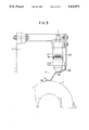
- FIG. 5 illustrates an example of a cake thickness sensor employing a proximity sensor.
- material to be deliquified or dewatered is supplied to the beltpress at a controllable rate through a variable speed feed pump.
- the material such as sludge
- the material is conveyed through the beltpress between at least two belts, which are separated by a progressively smaller distance as the sludge moves through the beltpress.
- liquid is squeezed from the sludge.
- Dewatered material in the form of cake is produced at the output of the beltpress.
- One or more thickness sensors measures the thickness of the cake. If multiple sensors are used, an average thickness can be determined. Given the width of the belt and the belt speed, the thickness information is used to determine the volume of output cake per unit time.
- Moisture content is then evaluated and, with the volume information derived from the thickness data, the output dry solids per unit time is determined.
- the output dry solids per unit time is compared against a setpoint and the speed of the variable speed feed pump is adjusted to achieve the desired rate.
- on-line measured cake thickness and belt speed are used by a controller to control sludge throughput by causing adjustment of the sludge feed pump speed.
- a polymer is mixed with the sludge.
- Polymer is supplied by a polymer dosing pump through an insert feed plate.
- the position of the insert feed plate controls the mixing energy.
- the position of the plate is adjusted according to sludge flow rate. Since sludge flow rate is set according to the rate of output dry solids per unit time, as determined by the on-line measured output cake thickness and belt speed, the position of the plate is related to cake thickness and belt speed.
- a streaming current detector measures the charge in the filtrate from the beltpress causing the speed of a polymer dosing pump to be adjusted accordingly.
- FIG. 1 illustrates a beltpress system 1 according to the invention.
- Feed port 3 is supplied with product for dewatering by variable speed feed pump 5 having a speed control input 6.
- the variable speed sludge pump 5 thus controls the rate of sludge flow, e.g. in gallons per minute.
- Within the beltpress I a pair of endless loop pressing belts 7 and 9 are used. The belts are moved over a series of rollers so as to squeeze liquid or other material from feed material 13, which is deposited on belt 7 by variable speed feed pump 5. The dewatered material is expelled after passage through the roller section as cake 15.
- one or more thickness sensors 17 measures the thickness of the expelled cake. As shown in FIG. 4, preferably three thickness sensors are located across the width of the belt used. One sensor 19 is located at the approximate center of the belt width, while the remaining two sensors 21 and 23 are located near the edges of the belt, inset from each edge by approximately 10% of the belt width, W.
- the cake thickness measured by these three sensors is averaged to arrived a single cake thickness value for a particular point in the time.
- Cake thickness can be measured continuously and sampled periodically, as required, to calculate the rate of output dry solids per unit time. Typically, cake thickness is sampled about once per minute and dry solid output rate is calculated in pounds of dry solids per hour. In the event that the cake thickness measurement results in adjustment of the variable speed sludge pump 5, the next cake thickness measurement can be delayed to allow time for the alteration of the feed pump 5 to affect the calculated rate of dry solids per unit time.
- Cake thickness can be measured using electromechanical, optical, or ultrasonic techniques.
- an electromechanical implementation of a thickness sensor employs a proximity sensor 25, such as the Electro-Mike Displacement Transducer made by Electro Corporation.
- Such displacement transducers generate a low level RF field in front of a sensor 27 so that eddy currents generated by a metal target 29 intercepted by the field disrupt the Q (Quality Factor) of the sensor.
- the change in Q is proportional to the distance from the sensor to the metal target 29.
- a typical linear gap range between the sensor and the target for such a sensor is 0.050 inches to 0.500 inches.
- the range of cake thickness to be measured is typically between 0.250 inches and 0.750 inches.
- transition portion 31 attached to pivot 33 in order to translate the cake thickness range to a range compatible with the proximity sensor.
- a lower portion 35 of the transition portion contacts upper belt 7.
- the distance between the upper and lower belts also decreases.
- the sensor provides to controller 37 a signal which typically varies between 4 mADC and 20 mADC depending on the measured cake thickness.
- controller 37 a signal which typically varies between 4 mADC and 20 mADC depending on the measured cake thickness.
- a controller can be employed to use other suitable signals and signal ranges and that the above is by way of illustration and not limitation.
- the proximity detector discussed above is also by way of illustration and not limitation, as any suitable optical, ultrasonic or other proximity sensor can be employed.
- FIG. 1 further shows polymer dosing pump 39, which mixes polymer with the input sludge to enhance dewatering.
- Streaming Current Detector (SCD) 41 measures particle charge on a treated sample by continuously drawing portions of the sample into a sealed chamber. Particles which have not reacted with the polymer tend to adhere to the surface of the chamber. Thus immobilized, they are subjected to a high velocity stream created by the motion of a reciprocating piston which drew the sample into the chamber.
- This stream severs ions from the loosely bound counterion layer surrounding each particle, forcing them to move in the same direction as the stream and creating an alternating electric current. This current is rectified and amplified and used as an input to controller 37 for controlling polymer dosing.
- the SCD reading decreases and the pump speed is altered so that the desired SCD reading is achieved.
- the SCD reading increases as the polymer decreases, and again the polymer dosing pump speed is altered to achieve the desired SCD value.
- Insert feed plate 45 which adjusts the size of the mixer orifice 47.
- Insert feed plate 45 varies from 0% open, where the mixer orifice is closed, to 100% open, where the mixer orifice is fully open. In the full open position, little mixing energy exists.
- the position of the insert feed plate 45 is determined by the sludge flow rate. As the sludge flow rate increases, the insert feed plate is opened further to reduce the mixing energy.
- sludge flow rate is a function of output dry solids per unit time as determined from on-line measured cake thickness and belt speed from sensor 50. Since the position of the insert feed plate 45 is a function of sludge flow rate, in the system according to the invention, mixing energy is related to output cake thickness.
- the polymer dosing control loop is typically a proportional plus integral plus derivative (PID) loop which receives a signal, typically between 4mADC and 20mAdC, from the SCD 41 and transmits a signal to the speed control input 43 of polymer dosing pump 39.
- PID proportional plus integral plus derivative
- Such PID loops for polymer dosing loops are conventional.
- the controller 37 responds by signalling the polymer dosing pump to operate faster to increase the polymer dosing to the desired level.
- the controlled variable is the SCD setpoint and the manipulated variable is the polymer dosing pump speed.
- the controller 37 also operates a sludge throughput control loop as illustrated in FIG. 2.
- the sludge throughput control loop is typically a proportional plus integral plus derivative (PID) control loop which operates to adjust sludge feed pump speed based on the cake thickness measured on-line by the cake thickness sensors.
- the cake thickness sensors discussed above typically provide signals between 4mADC and 20mADC, depending on the measured thickness, to controller or processor 37.
- the proportional gain and the derivative and integral times for the PID loop are determined from the response of the controlled variable to a step change in the manipulated variable.
- the manipulated variable is sludge feed pump speed.
- the controlled variable is the dry solid throughput in pounds of dry solid per hour as calculated from the cake thickness measured, belt speed, cake width and cake moisture.
- Belt speed can be measured by known techniques, for example, using a magnetic pickup.
- Cake width is typically set by the width of the belts 7 and 9. However, cake width could also be a measured value.
- cake moisture can be programmed into controller 37 after the moisture content of an output sample is determined using known techniques, for example by heating the sample in an oven. Alternatively, cake moisture can be an on-line measured value determined by any suitable moisture sensor.
- Controller 37 periodically determines the rate of output dry solids by calculating the product of the cake thickness, cake width, belt speed and moisture content represented as a percentage of dry solids.
- the product of the cake thickness, cake width and belt speed is the volume of output cake.
- controller 37 causes the speed of the sludge feed pump to be varied accordingly, thus controlling sludge flow.
- the above calculations are typically performed on at least one output cake sample per minute. However, following adjustment of sludge feed pump speed, a time delay can be built in to allow the adjusted sludge pump speed to have an effect on the cake output.
- FIG. 3 is a flow diagram showing steps in sludge throughput control according to the method of the invention.
- step 301 the integrity of the cake sensors is determined. This is accomplished by testing each cake sensor to determine if an analog output within the expected range is present. If a cake sensor test is failed, control passes to step 303 which causes the failure to be displayed on a video display or to be indicated by some other indicator, such as an audio indicator. Control then passes to step 305 which results in holding or pausing the operation of the sludge throughput control loop. The current operating parameters are saved, all automatic loop operation is halted and the system is placed in a manual mode in steps 307, 309, and 311 respectively.
- step 313 If the cake sensors are operational, control is passed to step 313 in which belt tension is checked. If belt tension measured by conventional sensors 51, is out of the specified range, step 315 causes the condition to be indicated to an operator and control passes to steps 307, 309, and 311, previously described to put the system in a manual mode.
- the SCD signal, mixer position sensor, and sludge flow sensors can all be tested to determine if they are operating within expected ranges, e.g. 4mADC to 20mADC.
- expected ranges e.g. 4mADC to 20mADC.
- operational ranges of the sensors are by way of example and not by way of limitation, as it would be known to those of ordinary skill that any suitable sensors could be employed and that the operational ranges of such sensors can be scaled to appropriate signal levels.
- step 317 Upon successful completion of testing in step 313, control is passed to step 317 where belt speed is calculated.
- belts 7 and 9 are operated at substantially the same speed.
- a magnetic pickup device operates continuously counting pulses. By periodically multiplying the count by a constant, the number of belt revolutions per unit time, or belt speed, is determined. It is also known to those of ordinary skill that by measuring the time between pulses and dividing this into a constant, the belt speed may be determined.
- step 319 the cake thickness is measured, scaled and the average of a plurality of sensors, e.g., 19, 21, 23, situated as previously described across the width of the belt, is determined.
- the sensor position is measured as a percentage of full scale so that a mm value times 1000 is obtained.
- the values are then summed and divided by 300 to obtain a scaled value in mm times 10 units.
- the cake thickness is measured periodically at a rate determined by the time constant of the throughput control loop.
- One typical example is performing cake thickness measurements every 60 seconds.
- step 321 the controller 37 calculates the error between the throughput setpoint and the actual value.
- the first step in this calculation is the determination the average density of the cake. This is calculated based on the average density of the dry solids and the density of water in pounds per cubic foot along with the current moisture content according to the following equation.
- AVDENS is the average density of dry solids in lb/cu ft.
- SD is solids density in lb/cu ft.
- WD is water density in lb/cu ft.
- Throughput can then be calculated using the average density and cake moisture to arrive at throughput of dry solids in pounds per hour by applying the following equation. It should be noted that it may be convenient to perform the calculation in units compatible with the sensors, e.g. in cm 3 /min, and convert to desired units, e.g., ft 3 /hr. ##EQU1##
- AD Average density of cake in lb/cu ft.
- CM Cake moisture in %.
- the error is simply the difference between the throughput setpoint and the current throughput calculated from the cake thickness and other parameters, as described above.
- step 323 the proportional, integral and derivative outputs for the control loop are calculated by controller or processor 37.
- the proportional output of the loop is the product of the gain and the error.
- the gain is set at system commissioning based on the output of the controller and the signal levels required for compatibility with the speed control input of the sludge feed pump 5.
- the integral term may be limited due by the integer range of the processor or controller 37.
- the derivative term and current error are also calculated and placed in a register.
- the equations for calculating the proportional, integral and derivative terms are given as:
- THS throughput set point in lb/hr.
- THC throughput calculated in lb/hr.
- TS Sample time constant in secs.
- THSUM is output value
- step 325 the above proportional, integral and derivative output terms are summed with the current measured sludge speed to arrive at total output term which is converted to a percent sludge pump speed adjustment required.
- step 327 the sludge feed pump speed is adjusted to maintain a constant throughput of output dry solids, based on the above calculations.
- the actual speed of the sludge feed pump is a function of the moisture content of the output cake. For example, if moisture content in the output cake of a second sample is 10% greater than the moisture content of the output cake in a previous sample, the sludge flow must be increased to maintain a constant rate of output of dry solids. This is accomplished by controller 37 which adjusts the speed of the sludge feed pump 5 by generating signals to vary the speed control 6.
- steps 329, 331, 333, and 335 respectively high and low limits for sludge speed and cake thickness are compared with the corresponding measured parameter.
- steps 337, 339, 341, and 343 generate corresponding displays and pass control to step 305 where loop termination begins, ultimately returning the system to the manual mode in step 311. If sludge speed and cake thickness are within the programmed limits, step 345 causes the throughput loop to be repeated.
- Controller 37 also operates a mixer control loop, which employs an actuator (such as an electric, hydraulic, or pneumatic actuator) that varies the orifice of the mixer according to changes in the sludge flow measured by sensor 49.
- the input variable is the sludge flow rate and the position of insert feed plate 45 is set based on the difference between the set flow rate and the current flow rate.
- a sludge flow sensor produces a signal between 4mADC and 20mADC indicating the current rate of sludge flow.
- a position sensor which provides a signal between 4mADC and 20mADC, indicates the current position of the insert feed plate 45.
- the main function of the mixer control loop is to maintain a constant mixing energy for any given sludge volume to achieve consistent flocculation and coagulation.
- Processor or controller 37 determines the required orifice size or insert feed plate position from a programmed relationship. This is a linear function of measured sludge flow and insert feed plate position.
- Slope and offset for the linear function at a particular installation are determined at commissioning time.
- the commissioning engineer is prompted to set up a number of optimum operating conditions for the beltpress.
- a particular value for sludge flow and mixer positions are stored by the controller 37, at the time when the commissioning engineer presses a button. This is carried out for a number of different sludge flows and consequent mixer positions.
- the slope and offset are then calculated using a least squares process from a minimum of three points, by the processor controller 37.
- Table 1 below lists typical operating values including sludge flow in gallons per minute and throughput in pounds of dry output solids per hour for a system configured as described herein. It should be noted that nothing in the invention constrains such systems to these particular ranges and that systems having other ranges can be also be assembled using suitable component parts.
Abstract
Description
AVDENS=[CM×SD+(100-CM)×WD]/100
P=(THS-THC)×TK
THSUM=P+I+D+SLSP
                                  TABLE 1
__________________________________________________________________________
         Nominal            Too Low Alarm
                                     Too High Alarm
Parameter
         Operating Value
                  Range     (Both Programmable)
__________________________________________________________________________
Sludge Flow
         60 gpm   30-120 gpm
                            20 gpm   140 gpm
Mixer Position
         25%      18-60%    15%      80%
Cake Thickness
         0.5"     0.25"-0.75"
                            0.15"    1"
Moisture Content
         20%      15-20%    N/A      N/A
Belt Speed
         5 m/min  1 m/min-20 m/min
                            N/A      N/A
Throughput
         1000 #/hr
                  400-1600 #/hr
                            N/A      N/A
% Solids 3%       0.7-5%    N/A      N/A
Polymer Dosing
         8 #/ton  5-11 #/ton
                            N/A      N/A
__________________________________________________________________________
Claims (30)
Priority Applications (1)
| Application Number | Priority Date | Filing Date | Title |
|---|---|---|---|
| US07/647,636 US5133872A (en) | 1991-01-31 | 1991-01-31 | Method and apparatus for controlling throughput in a beltpress |
Applications Claiming Priority (1)
| Application Number | Priority Date | Filing Date | Title |
|---|---|---|---|
| US07/647,636 US5133872A (en) | 1991-01-31 | 1991-01-31 | Method and apparatus for controlling throughput in a beltpress |
Publications (1)
| Publication Number | Publication Date |
|---|---|
| US5133872A true US5133872A (en) | 1992-07-28 |
Family
ID=24597732
Family Applications (1)
| Application Number | Title | Priority Date | Filing Date |
|---|---|---|---|
| US07/647,636 Expired - Lifetime US5133872A (en) | 1991-01-31 | 1991-01-31 | Method and apparatus for controlling throughput in a beltpress |
Country Status (1)
| Country | Link |
|---|---|
| US (1) | US5133872A (en) |
Cited By (23)
| Publication number | Priority date | Publication date | Assignee | Title |
|---|---|---|---|---|
| US5248416A (en) * | 1991-11-18 | 1993-09-28 | Howard Jr Ronnie E | Sewage treatment system |
| WO1995002441A1 (en) * | 1993-07-16 | 1995-01-26 | Adrian Parnaby | Apparatus and method for separating a mixture of a liquid and a solid |
| US5456832A (en) * | 1993-12-28 | 1995-10-10 | Komline-Sanderson Engineering Corp. | Apparatus for preparing a material for high pressure deliquification |
| WO1996025993A1 (en) * | 1995-02-23 | 1996-08-29 | Motorola Inc. | Cross-flow filtration control system and method |
| US5571404A (en) * | 1994-10-31 | 1996-11-05 | Pannevis B.V. | Belt filter with means to advance the belt responsive to a capacitance signal |
| US5865997A (en) * | 1996-04-17 | 1999-02-02 | Ashbrook Corporation | Scraper blade assembly |
| US5885445A (en) * | 1996-02-05 | 1999-03-23 | Thames Water Utilities Limited | Belt press for dewatering sludge |
| WO1999015255A1 (en) * | 1997-09-19 | 1999-04-01 | Baker Hughes Incorporated | Method and apparatus for monitoring, controlling and operating rotary drum filters |
| US20030178375A1 (en) * | 2002-03-25 | 2003-09-25 | Sharpe Mixers, Inc. | Method and apparatus for mixing additives with sludge in a powered line blender |
| US20080110838A1 (en) * | 2006-11-07 | 2008-05-15 | William Harris Moss | Belt press apparatus and method for high solids capture and high solids content |
| US20100032384A1 (en) * | 2008-08-07 | 2010-02-11 | William Harris Moss | Method for improving belt press dewatering |
| US20120285326A1 (en) * | 2010-02-26 | 2012-11-15 | Mitsubishi Heavy Industries, Ltd. | Gypsum dewatering device for desulfurization facility |
| US20150251112A1 (en) * | 2012-09-30 | 2015-09-10 | Daritech, Inc. | Splice systems and methods for ropes |
| JP2016022436A (en) * | 2014-07-22 | 2016-02-08 | ジャステック株式会社 | Solid-liquid separator |
| US9597618B2 (en) | 2009-11-05 | 2017-03-21 | Daritech, Inc. | Systems and methods for extracting sand from raw slurry material |
| US9610521B2 (en) | 2009-11-05 | 2017-04-04 | Daritech, Inc. | Systems and methods for extracting particulate from raw slurry material |
| WO2017070792A1 (en) | 2015-10-29 | 2017-05-04 | Salsnes Filter As | Method and process for operating and controlling a separation device |
| WO2017177202A1 (en) * | 2016-04-08 | 2017-10-12 | Remirez Jose Antonio | Automated dosing system and method with light profiling for wastewater filtration system |
| US10286340B2 (en) | 2014-05-27 | 2019-05-14 | Daritech, Inc. | Feed systems and methods for rotary screen separators |
| US10603611B2 (en) | 2014-05-30 | 2020-03-31 | Daritech, Inc. | Cleaning systems and methods for rotary screen separators |
| US10603675B2 (en) | 2014-11-02 | 2020-03-31 | Dari-Tech, Inc. | Systems and methods for extracting particulate from raw slurry material |
| CN112661378A (en) * | 2020-12-23 | 2021-04-16 | 佛山科学技术学院 | Control method of sludge dewatering machine system and sludge dewatering machine system |
| CN113582499A (en) * | 2020-04-30 | 2021-11-02 | 珠海市德旺绿色环保科技有限公司 | Regeneration production process for sludge resources generated by treating furnace washing slag |
Citations (12)
| Publication number | Priority date | Publication date | Assignee | Title |
|---|---|---|---|---|
| US3984329A (en) * | 1974-02-27 | 1976-10-05 | Lothar Wenzel | Device for extracting liquid from sludge |
| US4142971A (en) * | 1976-06-11 | 1979-03-06 | Degremont | Process and system for the dehydration of residues |
| US4576723A (en) * | 1983-12-02 | 1986-03-18 | Basf Aktiengesellschaft | Estimation of the degree of dispersion in flowing concentrated dispersions |
| US4587023A (en) * | 1984-08-31 | 1986-05-06 | Nalco Chemical Company | Control system for a process |
| US4612123A (en) * | 1983-01-25 | 1986-09-16 | Maschinenfabrik Andritz Actiengesellschaft | Regulating apparatus for dewatering machines |
| US4675116A (en) * | 1984-07-26 | 1987-06-23 | Water Research Centre | Dewatering solids suspensions with controlled flocculant addition |
| US4681033A (en) * | 1984-12-11 | 1987-07-21 | Rexnord Inc. | Drive system for belt press |
| US4707272A (en) * | 1985-03-18 | 1987-11-17 | Von Roll Ag | Method for controlling and optimizing the operation of a perforated belt press for filtering slurry |
| US4836100A (en) * | 1987-11-17 | 1989-06-06 | Ashbrook-Simon-Hartley Corporation | Apparatus for regulating feed thickness in a belt press |
| US4867886A (en) * | 1988-07-25 | 1989-09-19 | Westvaco Corporation | Method and apparatus for controlling sludge flocculant flow |
| US4990261A (en) * | 1987-11-19 | 1991-02-05 | Calgon Corporation | Method for monitoring and/or controlling liquid-solid separation processes |
| US5021166A (en) * | 1988-09-30 | 1991-06-04 | Patrick Torpey | Method and an apparatus for extracting a liquid from a sludge |
-
1991
- 1991-01-31 US US07/647,636 patent/US5133872A/en not_active Expired - Lifetime
Patent Citations (13)
| Publication number | Priority date | Publication date | Assignee | Title |
|---|---|---|---|---|
| US3984329A (en) * | 1974-02-27 | 1976-10-05 | Lothar Wenzel | Device for extracting liquid from sludge |
| US3984329B1 (en) * | 1974-02-27 | 1986-09-23 | ||
| US4142971A (en) * | 1976-06-11 | 1979-03-06 | Degremont | Process and system for the dehydration of residues |
| US4612123A (en) * | 1983-01-25 | 1986-09-16 | Maschinenfabrik Andritz Actiengesellschaft | Regulating apparatus for dewatering machines |
| US4576723A (en) * | 1983-12-02 | 1986-03-18 | Basf Aktiengesellschaft | Estimation of the degree of dispersion in flowing concentrated dispersions |
| US4675116A (en) * | 1984-07-26 | 1987-06-23 | Water Research Centre | Dewatering solids suspensions with controlled flocculant addition |
| US4587023A (en) * | 1984-08-31 | 1986-05-06 | Nalco Chemical Company | Control system for a process |
| US4681033A (en) * | 1984-12-11 | 1987-07-21 | Rexnord Inc. | Drive system for belt press |
| US4707272A (en) * | 1985-03-18 | 1987-11-17 | Von Roll Ag | Method for controlling and optimizing the operation of a perforated belt press for filtering slurry |
| US4836100A (en) * | 1987-11-17 | 1989-06-06 | Ashbrook-Simon-Hartley Corporation | Apparatus for regulating feed thickness in a belt press |
| US4990261A (en) * | 1987-11-19 | 1991-02-05 | Calgon Corporation | Method for monitoring and/or controlling liquid-solid separation processes |
| US4867886A (en) * | 1988-07-25 | 1989-09-19 | Westvaco Corporation | Method and apparatus for controlling sludge flocculant flow |
| US5021166A (en) * | 1988-09-30 | 1991-06-04 | Patrick Torpey | Method and an apparatus for extracting a liquid from a sludge |
Cited By (37)
| Publication number | Priority date | Publication date | Assignee | Title |
|---|---|---|---|---|
| US5248416A (en) * | 1991-11-18 | 1993-09-28 | Howard Jr Ronnie E | Sewage treatment system |
| WO1995002441A1 (en) * | 1993-07-16 | 1995-01-26 | Adrian Parnaby | Apparatus and method for separating a mixture of a liquid and a solid |
| US5456832A (en) * | 1993-12-28 | 1995-10-10 | Komline-Sanderson Engineering Corp. | Apparatus for preparing a material for high pressure deliquification |
| US5543044A (en) * | 1993-12-28 | 1996-08-06 | Komline- Sanderson Engineering Corp. | Apparatus for preparing a material for high pressure deliquification |
| US5545333A (en) * | 1993-12-28 | 1996-08-13 | Komline-Sanderson Engineering Corp. | Method for preparing a material for high pressure deliquification |
| US5571404A (en) * | 1994-10-31 | 1996-11-05 | Pannevis B.V. | Belt filter with means to advance the belt responsive to a capacitance signal |
| WO1996025993A1 (en) * | 1995-02-23 | 1996-08-29 | Motorola Inc. | Cross-flow filtration control system and method |
| GB2313329A (en) * | 1995-02-23 | 1997-11-26 | Motorola Inc | Cross-flow filtration control system and method |
| US5885445A (en) * | 1996-02-05 | 1999-03-23 | Thames Water Utilities Limited | Belt press for dewatering sludge |
| US5865997A (en) * | 1996-04-17 | 1999-02-02 | Ashbrook Corporation | Scraper blade assembly |
| WO1999015255A1 (en) * | 1997-09-19 | 1999-04-01 | Baker Hughes Incorporated | Method and apparatus for monitoring, controlling and operating rotary drum filters |
| US20030178375A1 (en) * | 2002-03-25 | 2003-09-25 | Sharpe Mixers, Inc. | Method and apparatus for mixing additives with sludge in a powered line blender |
| US6808305B2 (en) | 2002-03-25 | 2004-10-26 | Sharpe Mixers, Inc. | Method and apparatus for mixing additives with sludge in a powered line blender |
| US20050082232A1 (en) * | 2002-03-25 | 2005-04-21 | Sharpe Phil E. | Method and apparatus for mixing additives with sludge in a powered line blender |
| US7014775B2 (en) | 2002-03-25 | 2006-03-21 | Sharpe Mixers, Inc. | Method for mixing additives with sludge in a powered line blender |
| US20080110838A1 (en) * | 2006-11-07 | 2008-05-15 | William Harris Moss | Belt press apparatus and method for high solids capture and high solids content |
| US7381329B1 (en) * | 2006-11-07 | 2008-06-03 | William Harris Moss | Belt press apparatus and method for high solids capture and high solids content |
| US7964105B2 (en) * | 2008-08-07 | 2011-06-21 | William Harris Moss | Method for improving belt press dewatering |
| US20100032384A1 (en) * | 2008-08-07 | 2010-02-11 | William Harris Moss | Method for improving belt press dewatering |
| US9597618B2 (en) | 2009-11-05 | 2017-03-21 | Daritech, Inc. | Systems and methods for extracting sand from raw slurry material |
| US9610521B2 (en) | 2009-11-05 | 2017-04-04 | Daritech, Inc. | Systems and methods for extracting particulate from raw slurry material |
| US20120285326A1 (en) * | 2010-02-26 | 2012-11-15 | Mitsubishi Heavy Industries, Ltd. | Gypsum dewatering device for desulfurization facility |
| US8795516B2 (en) * | 2010-02-26 | 2014-08-05 | Mitsubishi Heavy Industries, Ltd. | Gypsum dewatering device for desulfurization facility |
| US20150251112A1 (en) * | 2012-09-30 | 2015-09-10 | Daritech, Inc. | Splice systems and methods for ropes |
| US10286340B2 (en) | 2014-05-27 | 2019-05-14 | Daritech, Inc. | Feed systems and methods for rotary screen separators |
| US10603611B2 (en) | 2014-05-30 | 2020-03-31 | Daritech, Inc. | Cleaning systems and methods for rotary screen separators |
| JP2016022436A (en) * | 2014-07-22 | 2016-02-08 | ジャステック株式会社 | Solid-liquid separator |
| US10603675B2 (en) | 2014-11-02 | 2020-03-31 | Dari-Tech, Inc. | Systems and methods for extracting particulate from raw slurry material |
| WO2017070792A1 (en) | 2015-10-29 | 2017-05-04 | Salsnes Filter As | Method and process for operating and controlling a separation device |
| EP3368182A4 (en) * | 2015-10-29 | 2018-09-05 | Salsnes Filter AS | Method and process for operating and controlling a separation device |
| US20180318736A1 (en) * | 2015-10-29 | 2018-11-08 | Salsnes Filter As | Method and Process for Operating and Controlling a Separation Device |
| US11389754B2 (en) * | 2015-10-29 | 2022-07-19 | U.S. Peroxide, Llc | Controlling a separation device |
| WO2017177202A1 (en) * | 2016-04-08 | 2017-10-12 | Remirez Jose Antonio | Automated dosing system and method with light profiling for wastewater filtration system |
| US10550019B2 (en) | 2016-04-08 | 2020-02-04 | OptikTechnik LLC | Automated dosing system and method with light profiling for wastewater filtration system |
| CN113582499A (en) * | 2020-04-30 | 2021-11-02 | 珠海市德旺绿色环保科技有限公司 | Regeneration production process for sludge resources generated by treating furnace washing slag |
| CN112661378A (en) * | 2020-12-23 | 2021-04-16 | 佛山科学技术学院 | Control method of sludge dewatering machine system and sludge dewatering machine system |
| CN112661378B (en) * | 2020-12-23 | 2022-03-25 | 佛山科学技术学院 | Control method of sludge dewatering machine system and sludge dewatering machine system |
Similar Documents
| Publication | Publication Date | Title |
|---|---|---|
| US5133872A (en) | Method and apparatus for controlling throughput in a beltpress | |
| JP2558196B2 (en) | Method and apparatus for supplying uniform continuous dough such as bread dough | |
| US4742228A (en) | Infrared measuring apparatus and process for the continuous quantitative determination of individual components of flour or other groundable food products | |
| US4855061A (en) | Method and apparatus for controlling the coagulant dosage for water treatment | |
| EP2789400A1 (en) | Application method for powder and application device and method for manufacturing heating element using same | |
| CA1147922A (en) | Method of extruding and shaping thermoplastic material | |
| US4867886A (en) | Method and apparatus for controlling sludge flocculant flow | |
| JP2004505276A (en) | Method and apparatus for packing a chromatography column and chromatography column | |
| EP3363625A1 (en) | Powdery material feeding device and powdery material feeding method | |
| US5269469A (en) | Method for measuring the fineness or bulk density, apparatus for carrying out the method and control system with such an apparatus | |
| WO1986004417A1 (en) | Method and device for the determination of characteristic values, particularly of grain | |
| US4731176A (en) | Control system for froth flotation processes | |
| US5003814A (en) | Sampling processes for use in the controlled addition of conditioning material to suspensions, sludges and the like and apparatus thereof | |
| CN107530663B (en) | Apparatus for producing granules | |
| SU1503687A3 (en) | Infrared measuring device for continuous qualitative analysis of components of flour or other milled food | |
| JPS607598B2 (en) | How to adjust the throughput of a roller press | |
| US5662805A (en) | Process and apparatus for controlling the dewatering of suspensions | |
| US4824581A (en) | Filtration apparatus control | |
| US5411669A (en) | Process and apparatus for treating pre-concentrated solid-liquid mixture streams | |
| CN114405156B (en) | Control method and control system of coal slime water pressure filter | |
| JP3741308B2 (en) | Method for constant control of moisture content of cake and control device therefor | |
| DE3032934C2 (en) | ||
| US5753273A (en) | System for monitoring and controlling the material composition and plastic or ductile deformation of the mass flow in a machine | |
| CA1318377C (en) | Sampling processes for use in the controlled addition of conditioning material to suspensions, sludges and the like and apparatus therefor | |
| US8820225B2 (en) | Apparatus and method for sensing and controlling the concentration of pulp in a concentrated pulp stream |
Legal Events
| Date | Code | Title | Description |
|---|---|---|---|
| AS | Assignment |
Owner name: ASHBROOK-SIMON-HARTLEY CORPORATION, TEXAS Free format text: ASSIGNMENT OF ASSIGNORS INTEREST.;ASSIGNORS:BALDWIN, PETER I.;MCKELL, KATHRYN E.;TRAN, KHAI;REEL/FRAME:005654/0535;SIGNING DATES FROM 19910313 TO 19910319 |
|
| STCF | Information on status: patent grant |
Free format text: PATENTED CASE |
|
| CC | Certificate of correction | ||
| FEPP | Fee payment procedure |
Free format text: PAYOR NUMBER ASSIGNED (ORIGINAL EVENT CODE: ASPN); ENTITY STATUS OF PATENT OWNER: LARGE ENTITY |
|
| FPAY | Fee payment |
Year of fee payment: 4 |
|
| FPAY | Fee payment |
Year of fee payment: 8 |
|
| FEPP | Fee payment procedure |
Free format text: PAYOR NUMBER ASSIGNED (ORIGINAL EVENT CODE: ASPN); ENTITY STATUS OF PATENT OWNER: LARGE ENTITY Free format text: PAYER NUMBER DE-ASSIGNED (ORIGINAL EVENT CODE: RMPN); ENTITY STATUS OF PATENT OWNER: LARGE ENTITY |
|
| REMI | Maintenance fee reminder mailed | ||
| FPAY | Fee payment |
Year of fee payment: 12 |
|
| SULP | Surcharge for late payment |
Year of fee payment: 11 |
|
| AS | Assignment |
Owner name: ASHBROOK SIMON-HARTLEY OPERATIONS, LP, TEXAS Free format text: ASSIGNMENT OF ASSIGNORS INTEREST;ASSIGNOR:ASHBROOK CORPORATION, FORMERLY KNOWN AS ASHBROOK-SIMON-HARTLEY CORPORATION AND ASHBROOK SIMON-HARTLEY INC.;REEL/FRAME:016967/0020 Effective date: 20050128 |