US5133561A - Sealing device - Google Patents
Sealing device Download PDFInfo
- Publication number
- US5133561A US5133561A US07/661,109 US66110991A US5133561A US 5133561 A US5133561 A US 5133561A US 66110991 A US66110991 A US 66110991A US 5133561 A US5133561 A US 5133561A
- Authority
- US
- United States
- Prior art keywords
- gas
- sealing
- face
- flange
- groove
- Prior art date
- Legal status (The legal status is an assumption and is not a legal conclusion. Google has not performed a legal analysis and makes no representation as to the accuracy of the status listed.)
- Expired - Lifetime
Links
Images


Classifications
-
- H—ELECTRICITY
- H01—ELECTRIC ELEMENTS
- H01L—SEMICONDUCTOR DEVICES NOT COVERED BY CLASS H10
- H01L21/00—Processes or apparatus adapted for the manufacture or treatment of semiconductor or solid state devices or of parts thereof
-
- C—CHEMISTRY; METALLURGY
- C23—COATING METALLIC MATERIAL; COATING MATERIAL WITH METALLIC MATERIAL; CHEMICAL SURFACE TREATMENT; DIFFUSION TREATMENT OF METALLIC MATERIAL; COATING BY VACUUM EVAPORATION, BY SPUTTERING, BY ION IMPLANTATION OR BY CHEMICAL VAPOUR DEPOSITION, IN GENERAL; INHIBITING CORROSION OF METALLIC MATERIAL OR INCRUSTATION IN GENERAL
- C23C—COATING METALLIC MATERIAL; COATING MATERIAL WITH METALLIC MATERIAL; SURFACE TREATMENT OF METALLIC MATERIAL BY DIFFUSION INTO THE SURFACE, BY CHEMICAL CONVERSION OR SUBSTITUTION; COATING BY VACUUM EVAPORATION, BY SPUTTERING, BY ION IMPLANTATION OR BY CHEMICAL VAPOUR DEPOSITION, IN GENERAL
- C23C16/00—Chemical coating by decomposition of gaseous compounds, without leaving reaction products of surface material in the coating, i.e. chemical vapour deposition [CVD] processes
- C23C16/44—Chemical coating by decomposition of gaseous compounds, without leaving reaction products of surface material in the coating, i.e. chemical vapour deposition [CVD] processes characterised by the method of coating
- C23C16/4401—Means for minimising impurities, e.g. dust, moisture or residual gas, in the reaction chamber
- C23C16/4409—Means for minimising impurities, e.g. dust, moisture or residual gas, in the reaction chamber characterised by sealing means
-
- C—CHEMISTRY; METALLURGY
- C23—COATING METALLIC MATERIAL; COATING MATERIAL WITH METALLIC MATERIAL; CHEMICAL SURFACE TREATMENT; DIFFUSION TREATMENT OF METALLIC MATERIAL; COATING BY VACUUM EVAPORATION, BY SPUTTERING, BY ION IMPLANTATION OR BY CHEMICAL VAPOUR DEPOSITION, IN GENERAL; INHIBITING CORROSION OF METALLIC MATERIAL OR INCRUSTATION IN GENERAL
- C23C—COATING METALLIC MATERIAL; COATING MATERIAL WITH METALLIC MATERIAL; SURFACE TREATMENT OF METALLIC MATERIAL BY DIFFUSION INTO THE SURFACE, BY CHEMICAL CONVERSION OR SUBSTITUTION; COATING BY VACUUM EVAPORATION, BY SPUTTERING, BY ION IMPLANTATION OR BY CHEMICAL VAPOUR DEPOSITION, IN GENERAL
- C23C16/00—Chemical coating by decomposition of gaseous compounds, without leaving reaction products of surface material in the coating, i.e. chemical vapour deposition [CVD] processes
- C23C16/44—Chemical coating by decomposition of gaseous compounds, without leaving reaction products of surface material in the coating, i.e. chemical vapour deposition [CVD] processes characterised by the method of coating
- C23C16/54—Apparatus specially adapted for continuous coating
-
- F—MECHANICAL ENGINEERING; LIGHTING; HEATING; WEAPONS; BLASTING
- F16—ENGINEERING ELEMENTS AND UNITS; GENERAL MEASURES FOR PRODUCING AND MAINTAINING EFFECTIVE FUNCTIONING OF MACHINES OR INSTALLATIONS; THERMAL INSULATION IN GENERAL
- F16J—PISTONS; CYLINDERS; SEALINGS
- F16J15/00—Sealings
- F16J15/002—Sealings comprising at least two sealings in succession
- F16J15/004—Sealings comprising at least two sealings in succession forming of recuperation chamber for the leaking fluid
-
- F—MECHANICAL ENGINEERING; LIGHTING; HEATING; WEAPONS; BLASTING
- F16—ENGINEERING ELEMENTS AND UNITS; GENERAL MEASURES FOR PRODUCING AND MAINTAINING EFFECTIVE FUNCTIONING OF MACHINES OR INSTALLATIONS; THERMAL INSULATION IN GENERAL
- F16J—PISTONS; CYLINDERS; SEALINGS
- F16J15/00—Sealings
- F16J15/46—Sealings with packing ring expanded or pressed into place by fluid pressure, e.g. inflatable packings
-
- Y—GENERAL TAGGING OF NEW TECHNOLOGICAL DEVELOPMENTS; GENERAL TAGGING OF CROSS-SECTIONAL TECHNOLOGIES SPANNING OVER SEVERAL SECTIONS OF THE IPC; TECHNICAL SUBJECTS COVERED BY FORMER USPC CROSS-REFERENCE ART COLLECTIONS [XRACs] AND DIGESTS
- Y10—TECHNICAL SUBJECTS COVERED BY FORMER USPC
- Y10S—TECHNICAL SUBJECTS COVERED BY FORMER USPC CROSS-REFERENCE ART COLLECTIONS [XRACs] AND DIGESTS
- Y10S277/00—Seal for a joint or juncture
- Y10S277/913—Seal for fluid pressure below atmospheric, e.g. vacuum
Definitions
- the present invention relates to a sealing device used at a seal portion of a member for shielding one gas atmosphere from the other gas atmosphere and, more particularly, to a sealing device used at a coupling portion of a wall for shielding the process atmosphere of a heat treatment apparatus from the open air.
- a furnace wall coupling of the CVD apparatus has a seal structure constituted by a seal member such as an O-ring so as to prevent the open air from entering the process atmosphere through a slight gap in the coupling.
- a sealing mechanism constituted by a combination of seal rings and an evacuation groove is disclosed in "Design parameters for differentially pumped rotating platforms", Rev. Sci. Instrum. 58(2), February 1987, p. 309, p. 310, U.S. Pat. No. 4,726,689.
- the above-mentioned sealing mechanism is formed by assembling coupling flanges 2 and 3.
- a plurality of seal rings 4 are inserted between flange 2 and flange 3, while a intermediate space 5 is formed between one seal ring 4 and other seal ring 4.
- Each seal ring consists of a resin member incorporating a spring.
- the intermediate space 5 is formed to be coaxial and parallel with the seal rings 4 and communicates with a suction portion of a vacuum pump through a path 6.
- a seal effect is obtained from a synergistic effect combined of the shielding effect by seal rings 4 and the evacuation effect by pumping through the intermediate space 5.
- the seal ring 4 of such a type is generally composed of a flexible fluororubber or an ethylene fluoride resin. These materials have heat resistance temperatures of about 200° C. at best. Therefore, if the operation temperature of the heat treatment apparatus exceeds the heat resistance temperature of the seal ring 4, the seal ring 4 is thermally deformed. As a result, a desired seal effect cannot be obtained. For this reason, portions near the seal rings 4 must be forcibly cooled to protect them.
- a CVD apparatus if an O-ring (seal ring) coupling portion is forcibly cooled, deposits (reacted product) of process gas components are produced on an inner wall portion of a process tube near the coupling, resulting in a nonuniform temperature distribution in the process tube.
- the process tube In order to prevent the cooled coupling portion from influencing a uniform temperature zone, the process tube must be elongated. This undesirably increases the longitudinal size of the CVD apparatus.
- each O-ring is set in a semi-molten state by heating during an operation.
- the CVD apparatus is stopped to replace the O-ring with a new one, since the O-ring adheres to the contact face of flange, it is difficult to detach the flanges from each other.
- this O-ring is detached, a quartz process tube may be damaged.
- the present inventors have conducted various studies on a mechanism capable of sealing a coupling portion of a heat treatment apparatus without using O-rings. As a result, the inventors have developed a sealing mechanism which can prevent a substantial deterioration in seal effect even if coupling flanges are thermally deformed by heating.
- a sealing device for preventing a gas from leaking through a coupling of a member for separating a first gas atmosphere from a second gas atmosphere comprises a first sealing member having a first sealing face, a second sealing member having a second sealing face which is in contact with the first sealing face of the first sealing member, at least one gas guide which is open to at least one of the first and second sealing faces of the first and second sealing members, and evacuation means for evacuating a region, in which the first and second sealing members are in contact with each other, through the gas guide.
- Such seal effect is based on the local pressure at the coupling portion and the pressure difference between the first and second gas atmospheres. Such a seal effect is called differential pumping.
- the seal effect is greatly increased by urging the elastic member against an open of the evacuation groove.
- the width of each of the evacuation grooves is preferably set in a range of 3 to 8 mm.
- FIG. 1 is a longitudinal sectional view showing a part of a conventional sealing mechanism
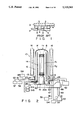
- FIG. 2 is a schematic view showing an overall arrangement of a vertical type CVD apparatus having a sealing mechanism according to an embodiment of the present invention
- FIG. 3 is a view showing a part of a three-groove type flange viewed from a seal surface
- FIG. 4 is a partial sectional view of the three-groove type flange viewed from a direction perpendicular to the seal surface;
- FIG. 5 is a view showing a part of a blind flange viewed from the side opposite to the seal surface
- FIG. 6 is a partial sectional view showing the blind flange viewed from a direction perpendicular to the seal surface
- FIG. 7 is a longitudinal sectional view showing portions of a grooved flange and a blind flange constituting a sealing mechanism of the first embodiment of the present invention
- FIG. 8 is a longitudinal sectional view showing a part of the sealing mechanism of the first embodiment in an operation state
- FIG. 9 is a longitudinal sectional view showing a part of a sealing mechanism, in an operation state, according to the second embodiment of the present invention.
- FIG. 10 is a longitudinal sectional view showing a part of a sealing mechanism, arranged on an intermediate coupling, according to the third embodiment
- FIG. 11 is an enlarged longitudinal sectional view showing a part of a sealing mechanism, according to the third embodiment.
- FIG. 12 is a graph showing the relation between a flange clamp force and leak rate
- FIG. 13 is a schematic view showing a test apparatus for checking the effect of differential pumping of a sealing mechanism having a three-groove type flange;
- FIG. 14 is a graph showing an experimental result of the differential pumping
- FIG. 15 is a schematic plan view showing an overall arrangement of an etcher/sputtering system having a sealing mechanism according to the fourth embodiment of the present invention.
- FIG. 16 is a schematic side view showing an overall arrangement of the etcher/sputtering system.
- FIG. 17 is an enlarged sectional view showing a part of a sealing mechanism used for a load lock chamber.
- a vertical type CVD apparatus 10 is arranged in a clean room having an air conditioner, and a large number of silicon wafers W mounted on a boat B are subjected to batch processing in a process tube 11.
- the CVD apparatus 10 is an automatic apparatus backed up by a computer system including a controller (not shown). For example, loading of the boat B, feeding of a process gas, and supply of power to a heater 16 are fully automatically controlled by the controller.
- the process tube 11 has a vertical cylindrical shape and is fixed to a frame (not shown) by a support member (not shown).
- the process tube 11 is surrounded by the heater 16.
- a power supply (not shown) of the heater 16 is controlled by the controller (not shown) to supply a proper current so as to set a desired temperature in the process tube 11. Note that the heating capacity of the heater 16 is adjusted to set a temperature range of 500° to 1,200° C. in the process tube 11.
- the process tube 11 is constituted by a quartz main tube 12 and a stainless steel manifold 20.
- the manifold 20 need not be made of a metal and may be made of quartz, SiC and other ceramic material.
- a flange 13 is formed on a lower opening end portion of the main tube 12.
- the flange 13 is connected to an upper flange of the cylindrical manifold 20.
- a lid member (blind flange) 40 is urged against a lower flange 22 of the manifold 20 to seal the lower opening of the process tube 11.
- An annular projection 20a is formed on the inner surface of the manifold 20.
- a cylindrical partition 14 is supported by the annular projection 20a.
- the interior of the process tube 11 is divided into a gas feed area A1 and a gas evacuation area A2 by the cylindrical partition 14.
- a gas inlet 26 extends through a lower side wall of the manifold 20 and communicates with the gas feed area A 1 .
- the gas inlet 26 communicates with a plurality of gas feed sources 51a, 51b, . . . through pipes.
- the plurality of gas feed sources 51a, 51b, . . . are used to store various types of gases such as monosilane gas, oxygen gas, hydrogen gas, and nitrogen gas.
- a gas outlet 28 extends through an upper side wall and communicates with the gas evacuation area A 2 .
- the gas outlet 28 communicates with an evacuation system 52 through a pipe.
- a heat-insulating cylinder 15 is mounted on the blind flange 40.
- the vertical type wafer boat B is mounted on the heat-insulating cylinder 15.
- the blind flange 40 is supported by a support member 47.
- a nut 48 of the support member 47 is threadably engaged with a vertical ball screw 49 of an elevating mechanism.
- three grooves 30, 32, and 34 are concentrically formed in a face of the lower flange 22 of the manifold 20.
- the first groove 31 is formed in an innermost portion of the face of the lower flange 22 and communicates with an air evacuation system 53 through a path 31.
- the second groove 32 is formed in an intermediate portion of the face of the lower flange 22 and communicates with an evacuation system 54 through a path 33.
- This evacuation system has an evacuation pump.
- the third groove 34 is formed in an outermost portion of the face of the lower flange 22 and communicates with a pressurizing system 55 through a path 35.
- the pressuring system 55 has a gas supply source reserved N 2 gas or air. Note that the opening of the third groove 34 is airtightly covered with a thin metal plate 44 throughout the groove.
- the metal thin plate 44 consists of a corrosion-resistant metal such as silver (Ag), nickel, or stainless steel.
- the sizes of the respective components of the lower flange 22 are: the thickness: 30 mm; the outer diameter of the face: 390 mm; the inner diameter of the face: 280 mm; the width of each of the grooves 30, 32, and 34: 5 mm; the depth of each of the grooves 30, 32, and 34: 8 mm; and the pitch of the grooves 30, 32, and 34: 15 mm.
- the width of each of the grooves 30, 32, and 34 is excessively increased, the face tends to be deformed.
- the width of each of the grooves 30, 32, and 34 is preferably set to be 3 to 8 mm.
- each of face portions 36, 37, 38, and 39 constituting the face of the lower flange 22 is finished to have a surface roughness of ⁇ 2 ⁇ m or less.
- the face constituted by these face portions 36, 37, 38, and 39 is finished to have a flatness of ⁇ 5 ⁇ m or less as a whole.
- the thin metal plate 44 has a thickness of 0.1 mm and a width of 10 mm. If the thickness of the metal thin plate 44 is excessively increased, expansion/ deformation thereof cannot be easily caused. In contrast to this, if the thickness of the thin metal plate 44 is excessively decreased, the plate 44 becomes susceptible to damage. For this reason, the thickness of the thin metal plate 44 is preferably set to be in the range of 0.05 mm to 0.25 mm. Although a seal effect can be expected to some extent without the thin metal plate 44 in a three-groove type sealing mechanism, the seal effect can be greatly enhanced with the thin metal plate 44.
- a face 42 of the blind flange 40 is finished to have a surface roughness of ⁇ 2 ⁇ m or less.
- the face 42 is finished to have a flatness of ⁇ 5 ⁇ m or less as a whole.
- the sizes of the respective components of the blind flange 40 are: the thickness: 15 mm; the outer diameter of the face: 390 mm; and the inner diameter of the face: 280 mm.
- the face 42 of the blind flange 40 is inwardly inclined downward from a horizontal plane at an inclination angle ⁇ .
- the inclination angle ⁇ of the face 42 is set to be an optimal value depending on conditions, e.g., the size of the flange 40, a material for the flange, and a width of the face 42.
- the blind flange 40 is constituted by a stainless steel (SUS 316) member having a diameter 300 mm and a thickness of 15 mm
- the inclination angle ⁇ is preferably set within a range of 0.01 to 0.1 degrees.
- the flange 13 of the main tube 12 is seal-connected to the upper flange 24 of the manifold 20.
- Three grooves 60, 62, and 64 are concentrically formed in the face of the upper flange 24 of the manifold 20.
- the first groove 60 is formed in an innermost portion of the face of the upper flange 24 and communicates with an evacuation system 56 through a path 61.
- the second groove 62 is formed in an intermediate portion of the face of the upper flange 24 and communicates with an another evacuation system 57 through a path 63.
- This evacuation system 57 has an evacuation pump.
- the third groove 64 is formed in an outermost portion of the face of the upper flange 24 and communicates with a pressuring system 58 through a path 65.
- the pressurizing system 58 has a gas supply source reserved N 2 gas and like. Note that the opening of the third groove 64 is airtightly covered with a thin metal plate 45 throughout the groove.
- This thin metal plate 45 consists of a corrosion-resistant metal such as silver (Ag), nickel, or stainless steel.
- the sizes of the respective components of the upper flange 24 are: the thickness 30 mm; the outer diameter of the face: 390 mm; the inner diameter of the face: 280 mm; the width of each of the grooves 60, 62, and 64: 5 mm; the depth of each of the grooves 60, 62, and 64: 8 mm; and the pitch of the grooves 60, 62, and 64: 15 mm. If the width of each of the grooves 60, 62, and 64 is excessively increased, the face tends to be deformed In contrast to this, if the width of each of the grooves 60, 62, and 64 is excessively decreased, sufficient evacuation cannot be performed. For this reason, the width of each of the grooves 60, 62, and 64 is preferably set in a range of 3 to 8 mm.
- each of face portions 66, 67, 68, and 69 constituting the face of the upper flange 24 may not necessary have high flatness, and, in the embodiment, each face portion is finished to have a surface roughness of ⁇ 2 ⁇ m or less.
- the face constituted by these face portions 66, 67, 68, and 69 is finished to have a flatness of ⁇ 5 ⁇ m or less as a whole.
- the sizes of the respective components of the flange 24 are: the thickness: 30 mm; the outer diameter of the face: 390 mm; and the inner diameter of the face: 280 mm.
- the thin metal plate 45 has a thickness of 0.1 mm and a width of 10 mm. In this case, the thickness of the thin metal plate 45 preferably falls within a range of 0.05 mm to 0.25 mm.
- a face 13a of the flange 13 of the main tube 12 is finished to have a flatness of ⁇ 5 ⁇ m or less.
- the sizes of the respective components of the flange 13 are: the thickness: 30 mm; the outer diameter of the face 13a: 390 mm; and the inner diameter of the face 13a: 280 mm.
- the process tube 11 is evacuated by the evacuation system 52. Meanwhile, all the evacuation systems 53, 54, 56 and 57, and the pressurizing systems 55 and 58 of the sealing mechanism are operated. While the first grooves 30 and 60 are respectively evacuated by the evacuation systems 53 and 56, the second grooves 32 and 62 are respectively evacuated by the evacuation systems 54 and 57. Meanwhile, nitrogen gas is fed from the pressurizing systems 55 and 58 into the third grooves 34 and 64 at a pressure of 1 to 5 kg/cm 2 to expand the thin plates 44 and 45. As a result, the thin plates 44 and 45 are respectively brought into tight contact with wide regions of the faces 42 and 13a of the opposite flanges, thus increasing the seal effect.
- an annular groove 62 is formed in a flange 13c of a main tube 12c, while an annular groove 64 is formed in an upper flange 24c of opening of the groove 64 on the lower side is covered by an elastic member, e.g., a thin metal plate 46.
- This thin plate 46 has a thickness of 0.1 to 0.2 mm and consists of stainless steel, nickel, copper, silver, or gold.
- the thin plate 46 may consist of an insulating material, e.g., Teflon, polyimide, or ceramics, or a semiconductor material, e.g., silicon.
- the thin metal plate 46 and the opening of the groove 62 on the upper side are positioned to oppose each other.
- the groove 62 on the upper side communicates with an evacuation system (not shown) through an annular expanded space 70 and a path 63.
- the groove 64 on the lower side communicates with a pressurizing system (not shown) through a path 65 having a small diameter.
- the sealing device can be made applicable by only setting an atmospheric pressure in the groove 64 depending on an application purpose. This is because the thin metal plate 46 is firmly sucked by the evacuation pressure of the opposite groove 62.
- the main evacuation systems 52 may be partially used for groove evacuation systems.
- FIG. 11 is an enlarged view of this state.
- FIG. 11 show a state wherein the groove 62 is evacuated by a vacuum pump or the like to a negative pressure, and the thin metal plate 46 is deformed, so that the deformed portion 46A is brought into contact with the edge portion 71 of the groove 62. More specifically, the thin metal plate 46 is brought into contact with outer and inner ring-like edge portions 71A and 71B formed on the groove 62.
- the width of the groove 64 is set to larger than that of the groove 62.
- the width of the groove 62 may be set to be larger than that of the groove 64.
- the present invention can be effectively applied to a seal portion between a flange 13c of the quartz main tube (or silica glass vessel) 12 and a flange 24c of the metal manifold 20c, which can tolerate only a limited clamping force, such as a quartz reaction chamber. This effect will be described in detail below.
- a seal surface roughness of each of the flange 13c and the thin metal plate 46 of the flange 24c was set to be about 0.1 ⁇ m or less.
- FIG. 12 shows the effects of such a clamping force. It is apparent that the leak rate is considerably increased even with application of a slight clamping force as compared with a case wherein no clamping force is applied.
- a clamping force required for a general metal O-ring is about 10 to 50 kg/mm. It is apparent, therefore, that a sufficient seal effect can be obtained with a clamping force less than 1/10 that of this conventional technique.
- the width of the groove 62 is preferably set to be 3 to 8 mm.
- the width of the groove 62 is determined in accordance with a material for the elastic member. If, for example, 0.2 mm thick elastic member consisting of stainless steel is used, and the width of the groove 62 is set to be smaller than 3 mm, he double seal effect is reduced. If the width of the groove 62 is set to be larger than 8 mm, the service life of the device is shortened because the degree of expansion/contraction of the elastic member is increased.
- the groove 64 may be set at an atmospheric pressure or may be pressurized.
- the groove 64 can be properly pressurized by feeding air or an inert gas such as N 2 gas.
- FIG. 13 Three concentrical grooves are formed in a face of an upper flange 81 of a helium leak test apparatus shown in FIG. 13.
- a flange having a flat face see the face 42a in FIG. 10
- a flange having a tapered surface inclined inward see the face 42 in FIG. 7
- a flange having a tapered surface inclined outward see the face 42 in FIG. 7, which tapered in the opposite direction
- An outer atmosphere of a coupling seal portion 83 between the upper and lower flanges 81 and 82 is filled with helium gas.
- the upper and lower flanges 81 and 82 are composed of an aluminum alloy.
- TMP turbo-molecular pump
- Another rotary pump 92 is arranged on the downstream side of the helium leak detector 91.
- a switching valve 87 is arranged in a pipe 86 between the TMP 85 and the rotary pump 88.
- a switching valve 89 is also arranged in a pipe 90 between the TMP 85 and the helium leak detector 91.
- a vacuum rate indicator 97 is connected by cable on the vacuum gauge head 96 arranged in a branch path.
- the grooves in the upper flange 81 respectively communicate with the inlet ports of rotary pumps 93a, 93b, and 93c.
- Pressure gauges 95a, 95b, and 95c and valves 94a, 94b, and 94c are arranged in the respective communicating pipes.
- the valve 87 is kept open to evacuate the measuring system until the measuring system is stabilized. At the same time, the valves 94a, 94b, and 94c are opened to evacuate the sealing mechanism. When the background of the measuring system is stabilized, the valve 87 is closed, and the valve 89 is opened to evacuate in the direction of the helium detector 91. With this operation, an amount of helium gas leaking into the measuring system through the flange coupling portion 83 is detected.
- FIG. 14 is a graph in which the positions of three ring-like grooves are plotted along the axis of abscissa, and differential evacuation pressures and leak rates at the respective groove positions are plotted along the axis of ordinate, thus showing a relationship between an evacuation pressure and a leak rate in each groove in each of the sealing devices shown in FIGS. 2 to 12. That is, this graph shows results obtained by conducting tests using the three types of lower flanges 82 respectively having the flat face (type A) shown in FIGS. 9, 10, and 13A, the tapered face descending inward (type B) shown in FIGS. 7, and 8, and the tapered face descending outward (type B).
- the inclinations of the types B and C are about several tens ⁇ m. Referring to FIG.
- a curve plotted along blank circles represents a result associated with the type B; a curve plotted along sold circles, a result associated with the type A; and a curve plotted along triangles, a result associated with the type C.
- Torr. l/sec used as a unit of leak rate is converted into a helium leak amount of 3.54 ⁇ 10 19 per second at a temperature of 0° C.
- a sealing mechanism of the fifth embodiment of the present invention will be described below with reference to FIGS. 15 to 17, which is applied to a load lock chamber of an etcher/sputtering system.
- the etcher/sputtering system has a plurality of process chambers 101, 102, and 103.
- Load locks 107 are respectively attached to openings 111 of partition walls 108 of the chambers 101, 102, and 103.
- Each of the chambers 101, 102, and 103 is airtight and is evacuated by an evacuation unit (not shown).
- the load locks 107 serve to load/unload silicon wafers W in/from the chambers 101, 102, and 103, respectively.
- the load locks 107 are frequently opened and closed. For this reason, the load locks 107 are designed to completely prevent the open air and dust from entering the chambers 101, 102, and 103 during a process of the silicon wafers W and to be quickly opened/closed during a non-process period.
- a door 112 of each load lock 107 is formed to seal the opening 111 of the partition wall 108 and to be freely opened and closed.
- the door 112 and the partition wall 108 are formed from stainless steel. Faces 115 and 109 of the door 112 and the partition wall 108 are mirror-finished.
- a groove 114 is formed near a peripheral portion of the door 112 so as to be open to the face 113.
- the groove 114 communicates with a pressurized gas feed source (not shown). Note that the pressure of a gas fed from the pressurized gas feed source need not be higher than the atmospheric pressure as long as it is larger than the pressure at the groove 110 in the partition wall 108.
- the opening of the groove 114 is covered by a thin metal plate 115.
- the thin metal plate 115 is welded/fixed to an entire peripheral face portion of the door 112.
- This thin metal plate 115 has a thickness of 0.2 mm and consists of a corrosion-resistant metal such as silver (Ag), nickel, or stainless steel.
- a groove 110 is formed in each partition wall 108 near the opening 111 so as to be open to the face 109.
- the thin metal plate 115 is brought into contact with the opening of the groove 110.
- Each groove 110 communicates with an evacuation system (not shown).
- the silicon wafers W are inserted in the chamber 101.
- the door 112 of the load lock 107 is then closed to evacuate the chamber 101.
- the groove 110 of the partition wall 108 is evacuated at about 10 -3 Torr or less, while a pressurized gas is fed into the groove 114 of the door 112 at a pressure of 2 kg/cm 2 or atmosphere.
- the thin metal plate 115 is pressed by differential of internal pressure of groove 110 and that of groove 114 to expand so as to be brought into tight contact with the opening of the groove 110.
- the internal pressure of the chamber 101 becomes a desired pressure of 10 -6 to 10 -8 Torr by using turbo molecular pump.
- the minimum leak rate is obtained by the conditions of No. 2, and an optimal gas pressure is about 2 kg/cm 2 Note that since the door or the partition wall is deformed with an clamping force is limited.
- the sealing mechanism of the present invention Since no O-rings are used for the sealing mechanism of the present invention, a stable sealing function can be maintained for a long period of time. Especially, the sealing mechanism can be effectively applied to a flange coupling portion of a heat treatment apparatus because the portion is heated to a high temperature.
- the sealing mechanism of the present invention can be applied to a vacuum CVD furnace, an atmospheric CVD furnace, a diffusion furnace, an etching apparatus, and the like.
- the sealing mechanism can be applied to an ion implanter, a spin coater apparatus, and the like.
- sealing mechanism of the present invention reduction rate of semiconductor wafer surfaces can be greatly reduced as compared with a conventional sealing mechanism. Therefore, a semiconductor having desired quality can be obtained, and the fraction defective can be reduced, thus greatly increasing the yield of products.
Abstract
Description
              TABLE 1
______________________________________
       Clamping Force
                    Gas Pressure Leak Rate
No.    (kg/cm.sup.2)
                    (kg/cm.sup.2)
                                 (Torr. l/sec)
______________________________________
1      3.54         5            5.5 × 10.sup.-11
2      3.54         2            5.5 × 10.sup.-11
3      2.50         2            1.3 × 10.sup.-10
4      1.50         2            2.0 × 10.sup.-10
5      0.50         2            3.2 × 10.sup.-10
6      0            2            8.0 × 10.sup.-10
7      0            1            1.2 × 10.sup.-9
8      0            0            2.4 × 10.sup.-8
______________________________________
Claims (14)
Applications Claiming Priority (6)
| Application Number | Priority Date | Filing Date | Title |
|---|---|---|---|
| JP2-45211 | 1990-02-26 | ||
| JP2045211A JP2733532B2 (en) | 1990-02-26 | 1990-02-26 | Heat treatment equipment |
| JP2-71562 | 1990-03-20 | ||
| JP2071562A JP2700939B2 (en) | 1990-03-20 | 1990-03-20 | Sealing device |
| JP22287290A JP2849772B2 (en) | 1990-08-24 | 1990-08-24 | Sealing device and sealing method |
| JP2-222872 | 1990-08-24 |
Publications (1)
| Publication Number | Publication Date |
|---|---|
| US5133561A true US5133561A (en) | 1992-07-28 |
Family
ID=27292158
Family Applications (1)
| Application Number | Title | Priority Date | Filing Date |
|---|---|---|---|
| US07/661,109 Expired - Lifetime US5133561A (en) | 1990-02-26 | 1991-02-26 | Sealing device |
Country Status (2)
| Country | Link |
|---|---|
| US (1) | US5133561A (en) |
| KR (1) | KR0171600B1 (en) |
Cited By (42)
| Publication number | Priority date | Publication date | Assignee | Title |
|---|---|---|---|---|
| US5368648A (en) * | 1991-02-26 | 1994-11-29 | Tokyo Electron Sagami Kabushiki Kaisha | Sealing apparatus |
| US5533736A (en) * | 1992-06-01 | 1996-07-09 | Tokyo Electron Kabushiki Kaisha | Thermal processing apparatus |
| US5578132A (en) * | 1993-07-07 | 1996-11-26 | Tokyo Electron Kabushiki Kaisha | Apparatus for heat treating semiconductors at normal pressure and low pressure |
| US5653479A (en) * | 1996-02-02 | 1997-08-05 | Vlsi Technology, Inc. | Vacuum seal for a ball junction |
| US5709840A (en) * | 1996-01-11 | 1998-01-20 | Tecan Us., Inc. | Reactor flask |
| US5711917A (en) * | 1996-01-11 | 1998-01-27 | Tecan U.S. | Laboratory reactor apparatus |
| WO1998053232A1 (en) * | 1997-05-16 | 1998-11-26 | Balzers Hochvakuum Ag | Intermediate metallic layer for flat packing which can be subjected to high stresses, and method for producing a flat packing with such intermediate layer |
| WO1999050577A1 (en) * | 1998-03-27 | 1999-10-07 | Asyst Technologies, Inc. | Kinematic coupling compatible, passive interface seal |
| EP1082470A1 (en) * | 1998-05-05 | 2001-03-14 | Ultratech Stepper Inc. | Microchamber |
| US6271530B1 (en) * | 1999-04-19 | 2001-08-07 | Applied Materials, Inc. | Apparatus for reducing distortion in fluid bearing surfaces |
| US6283175B1 (en) * | 1998-08-19 | 2001-09-04 | Tokyo Electron Limited | Enveloping device and vertical heat-treating apparatus for semiconductor process system |
| US6443618B1 (en) * | 2000-07-24 | 2002-09-03 | Moore Epitaxial, Inc. | Particulate free air bearing and seal |
| US20020180159A1 (en) * | 2000-12-13 | 2002-12-05 | Nsk Ltd. | Sealing device and positioning device using the same |
| US6491435B1 (en) | 2000-07-24 | 2002-12-10 | Moore Epitaxial, Inc. | Linear robot |
| US20030002756A1 (en) * | 2000-02-01 | 2003-01-02 | Shinji Shinohara | Hydrostatic gas bearing, hydrostatic gas bearing device for use in vacuum environment, and gas recovering method for the hydrostatic gas bearing device |
| US20030075871A1 (en) * | 2001-10-24 | 2003-04-24 | Hiroyuki Shinozaki | Differential pumping seal apparatus |
| US20030116280A1 (en) * | 2001-08-20 | 2003-06-26 | David Robinson | Apparatus and method for insulating a seal in a process chamber |
| US6666457B2 (en) * | 2000-08-10 | 2003-12-23 | Hans Georg Genser | Sealing device for sealing a cavity rotatable about a rotation axis |
| US20040234361A1 (en) * | 2003-04-14 | 2004-11-25 | Nsk Ltd. | Positioning device |
| US20060213438A1 (en) * | 2005-03-28 | 2006-09-28 | Tokyo Electron Limited | Plasma enhanced atomic layer deposition system |
| US20070031600A1 (en) * | 2005-08-02 | 2007-02-08 | Devitt Andrew J | Method and a device for depositing a film of material or otherwise processing or inspecting, a substrate as it passes through a vacuum environment guided by a plurality of opposing and balanced air bearing lands and sealed by differentially pumped groves and sealing lands in a non-contact manner |
| US20070059130A1 (en) * | 2005-08-18 | 2007-03-15 | Flitsch Frederick A | Method and apparatus to support a cleanspace fabricator |
| US20070087533A1 (en) * | 2005-10-19 | 2007-04-19 | Moore Epitaxial Inc. | Gas ring and method of processing substrates |
| US20070157683A1 (en) * | 2005-12-19 | 2007-07-12 | Tokyo Electron Limited | Method and system for sealing a first assembly to a second assembly of a processing system |
| US20070209590A1 (en) * | 2006-03-08 | 2007-09-13 | Tokyo Electron Limited | Sealing device and method for a processing system |
| US20070209588A1 (en) * | 2006-03-08 | 2007-09-13 | Tokyo Electron Limited | Exhaust system for a vacuum processing system |
| US20080292430A1 (en) * | 2007-05-21 | 2008-11-27 | Centrotherm Photovoltaics Ag | Device for doping, deposition or oxidation of semiconductor material at low pressure |
| US20100209226A1 (en) * | 2005-06-18 | 2010-08-19 | Flitsch Frederick A | Method and apparatus to support process tool modules in a cleanspace fabricator |
| US20100207381A1 (en) * | 2007-09-10 | 2010-08-19 | Alain Cornut Gentille | Pipe connector production method |
| CN102767656A (en) * | 2011-05-02 | 2012-11-07 | 克朗斯股份公司 | Heatable flange |
| US20130153201A1 (en) * | 2010-12-30 | 2013-06-20 | Poole Ventura, Inc. | Thermal diffusion chamber with cooling tubes |
| US20150014936A1 (en) * | 2013-07-11 | 2015-01-15 | Fanuc Corporation | Machine tool including sealing structure in rotation unit |
| US9059227B2 (en) | 2005-06-18 | 2015-06-16 | Futrfab, Inc. | Methods and apparatus for vertically orienting substrate processing tools in a clean space |
| US9263309B2 (en) | 2005-06-18 | 2016-02-16 | Futrfab, Inc. | Method and apparatus for an automated tool handling system for a multilevel cleanspace fabricator |
| DE102015104556A1 (en) * | 2015-03-26 | 2016-09-29 | Z & J Technologies Gmbh | Triple sealing seat with gas flushing for a draft tube valve |
| US9793146B2 (en) | 2005-06-18 | 2017-10-17 | Futrfab, Inc. | Method of forming a cleanspace fabricator |
| US10203054B2 (en) * | 2013-10-14 | 2019-02-12 | Edwards Limited | Vacuum system pipe couplings |
| CN106015616B (en) * | 2015-03-26 | 2019-07-16 | Z&J技术有限公司 | By the triple seal seat for conduit gate valve of air scour |
| US20200058523A1 (en) * | 2018-08-20 | 2020-02-20 | Ingentec Corporation | Gas etching device |
| US10627809B2 (en) | 2005-06-18 | 2020-04-21 | Frederick A. Flitsch | Multilevel fabricators |
| US10651063B2 (en) | 2005-06-18 | 2020-05-12 | Frederick A. Flitsch | Methods of prototyping and manufacturing with cleanspace fabricators |
| US11024527B2 (en) | 2005-06-18 | 2021-06-01 | Frederick A. Flitsch | Methods and apparatus for novel fabricators with Cleanspace |
Citations (20)
| Publication number | Priority date | Publication date | Assignee | Title |
|---|---|---|---|---|
| GB294538A (en) * | 1927-07-25 | 1929-07-11 | Aktiengesellschaft Brown Boveri & Cie. | |
| US1826941A (en) * | 1926-04-02 | 1931-10-13 | La Mont Corp | Method and means for preventing leakage in valves |
| US1888026A (en) * | 1925-03-19 | 1932-11-15 | Ralph E Chapman | Balanced joint |
| GB606032A (en) * | 1945-01-13 | 1948-08-05 | Trico Products Corp | Improvements in or relating to packing for fluid motors |
| US2987218A (en) * | 1958-03-26 | 1961-06-06 | Black Sivalls & Bryson Inc | Safety pressure relief device |
| GB950062A (en) * | 1959-07-23 | 1964-02-19 | Dunlop Rubber Co | Vacuum operated sealing means |
| GB958345A (en) * | 1961-12-27 | 1964-05-21 | Alpura Ag | Seals for pipe joints and the like |
| US3144035A (en) * | 1963-02-01 | 1964-08-11 | Nat Res Corp | High vacuum system |
| US3645545A (en) * | 1970-07-30 | 1972-02-29 | Ibm | Entrance-exit atmospheric isolation device |
| GB1375942A (en) * | 1973-01-05 | 1974-12-04 | Revertex Ltd | Fluid pressure seals |
| JPS5659064A (en) * | 1979-10-15 | 1981-05-22 | Kouenerugii Butsurigaku Kenkyusho | Double seal type valve of intermediate exhaustion |
| DE3203530A1 (en) * | 1982-02-03 | 1983-08-11 | Krupp Mak Maschinenbau Gmbh, 2300 Kiel | Sealing element |
| US4406458A (en) * | 1980-11-07 | 1983-09-27 | Max-Planck-Gesellschaft | Flange seal |
| US4450786A (en) * | 1982-08-13 | 1984-05-29 | Energy Conversion Devices, Inc. | Grooved gas gate |
| US4544317A (en) * | 1984-04-16 | 1985-10-01 | International Business Machines Corporation | Vacuum-to-vacuum entry system apparatus |
| SU1216525A1 (en) * | 1983-04-29 | 1986-03-07 | Институт ядерной энергетики АН БССР | Arrangement for glass hermetic sealing |
| US4626002A (en) * | 1984-01-18 | 1986-12-02 | Mtu | Self-acting seal between adjacent pipe ends of a pressure vessel |
| US4726689A (en) * | 1986-10-22 | 1988-02-23 | Eclipse Ion Technology, Inc. | Linear gas bearing with integral vacuum seal for use in serial process ion implantation equipment |
| US4735421A (en) * | 1982-08-10 | 1988-04-05 | The United States Of America As Represented By The United States Department Of Energy | Sealing apparatus utilizing a conformable member |
| US4799692A (en) * | 1986-08-12 | 1989-01-24 | The Regents Of The University Of California | Radial pressure flange seal |
-
1991
- 1991-02-26 KR KR1019910003099A patent/KR0171600B1/en not_active IP Right Cessation
- 1991-02-26 US US07/661,109 patent/US5133561A/en not_active Expired - Lifetime
Patent Citations (20)
| Publication number | Priority date | Publication date | Assignee | Title |
|---|---|---|---|---|
| US1888026A (en) * | 1925-03-19 | 1932-11-15 | Ralph E Chapman | Balanced joint |
| US1826941A (en) * | 1926-04-02 | 1931-10-13 | La Mont Corp | Method and means for preventing leakage in valves |
| GB294538A (en) * | 1927-07-25 | 1929-07-11 | Aktiengesellschaft Brown Boveri & Cie. | |
| GB606032A (en) * | 1945-01-13 | 1948-08-05 | Trico Products Corp | Improvements in or relating to packing for fluid motors |
| US2987218A (en) * | 1958-03-26 | 1961-06-06 | Black Sivalls & Bryson Inc | Safety pressure relief device |
| GB950062A (en) * | 1959-07-23 | 1964-02-19 | Dunlop Rubber Co | Vacuum operated sealing means |
| GB958345A (en) * | 1961-12-27 | 1964-05-21 | Alpura Ag | Seals for pipe joints and the like |
| US3144035A (en) * | 1963-02-01 | 1964-08-11 | Nat Res Corp | High vacuum system |
| US3645545A (en) * | 1970-07-30 | 1972-02-29 | Ibm | Entrance-exit atmospheric isolation device |
| GB1375942A (en) * | 1973-01-05 | 1974-12-04 | Revertex Ltd | Fluid pressure seals |
| JPS5659064A (en) * | 1979-10-15 | 1981-05-22 | Kouenerugii Butsurigaku Kenkyusho | Double seal type valve of intermediate exhaustion |
| US4406458A (en) * | 1980-11-07 | 1983-09-27 | Max-Planck-Gesellschaft | Flange seal |
| DE3203530A1 (en) * | 1982-02-03 | 1983-08-11 | Krupp Mak Maschinenbau Gmbh, 2300 Kiel | Sealing element |
| US4735421A (en) * | 1982-08-10 | 1988-04-05 | The United States Of America As Represented By The United States Department Of Energy | Sealing apparatus utilizing a conformable member |
| US4450786A (en) * | 1982-08-13 | 1984-05-29 | Energy Conversion Devices, Inc. | Grooved gas gate |
| SU1216525A1 (en) * | 1983-04-29 | 1986-03-07 | Институт ядерной энергетики АН БССР | Arrangement for glass hermetic sealing |
| US4626002A (en) * | 1984-01-18 | 1986-12-02 | Mtu | Self-acting seal between adjacent pipe ends of a pressure vessel |
| US4544317A (en) * | 1984-04-16 | 1985-10-01 | International Business Machines Corporation | Vacuum-to-vacuum entry system apparatus |
| US4799692A (en) * | 1986-08-12 | 1989-01-24 | The Regents Of The University Of California | Radial pressure flange seal |
| US4726689A (en) * | 1986-10-22 | 1988-02-23 | Eclipse Ion Technology, Inc. | Linear gas bearing with integral vacuum seal for use in serial process ion implantation equipment |
Non-Patent Citations (1)
| Title |
|---|
| Design Parameters for Differentially Pumped Rotating Platforms, Rev. Sci. Instrum. 58(2), Feb. 1987. * |
Cited By (71)
| Publication number | Priority date | Publication date | Assignee | Title |
|---|---|---|---|---|
| US5368648A (en) * | 1991-02-26 | 1994-11-29 | Tokyo Electron Sagami Kabushiki Kaisha | Sealing apparatus |
| US5884917A (en) * | 1992-06-01 | 1999-03-23 | Tokyo Electron Tohoku Kabushiki Kaisha | Thermal processing apparatus |
| US5533736A (en) * | 1992-06-01 | 1996-07-09 | Tokyo Electron Kabushiki Kaisha | Thermal processing apparatus |
| US5578132A (en) * | 1993-07-07 | 1996-11-26 | Tokyo Electron Kabushiki Kaisha | Apparatus for heat treating semiconductors at normal pressure and low pressure |
| US5711917A (en) * | 1996-01-11 | 1998-01-27 | Tecan U.S. | Laboratory reactor apparatus |
| US5709840A (en) * | 1996-01-11 | 1998-01-20 | Tecan Us., Inc. | Reactor flask |
| US5653479A (en) * | 1996-02-02 | 1997-08-05 | Vlsi Technology, Inc. | Vacuum seal for a ball junction |
| WO1998053232A1 (en) * | 1997-05-16 | 1998-11-26 | Balzers Hochvakuum Ag | Intermediate metallic layer for flat packing which can be subjected to high stresses, and method for producing a flat packing with such intermediate layer |
| US6182973B1 (en) | 1997-05-16 | 2001-02-06 | Balzers Hochvakuum Ag | Intermediate metallic layer for flat packing and process for the production of a flat packing with such an intermediate layer |
| US6550776B2 (en) * | 1997-05-16 | 2003-04-22 | Roman Schertler | Intermediate metallic layer for flat packing and process for the production of a flat packing with such an intermediate layer |
| WO1999050577A1 (en) * | 1998-03-27 | 1999-10-07 | Asyst Technologies, Inc. | Kinematic coupling compatible, passive interface seal |
| US6164664A (en) * | 1998-03-27 | 2000-12-26 | Asyst Technologies, Inc. | Kinematic coupling compatible passive interface seal |
| EP1082470A1 (en) * | 1998-05-05 | 2001-03-14 | Ultratech Stepper Inc. | Microchamber |
| EP1082470A4 (en) * | 1998-05-05 | 2003-02-05 | Ultratech Stepper Inc | Microchamber |
| US6283175B1 (en) * | 1998-08-19 | 2001-09-04 | Tokyo Electron Limited | Enveloping device and vertical heat-treating apparatus for semiconductor process system |
| US6271530B1 (en) * | 1999-04-19 | 2001-08-07 | Applied Materials, Inc. | Apparatus for reducing distortion in fluid bearing surfaces |
| US20030002756A1 (en) * | 2000-02-01 | 2003-01-02 | Shinji Shinohara | Hydrostatic gas bearing, hydrostatic gas bearing device for use in vacuum environment, and gas recovering method for the hydrostatic gas bearing device |
| US20060093244A1 (en) * | 2000-02-01 | 2006-05-04 | Shinji Shinohara | Hydrostatic gas bearing, hydrostatic gas bearing device for use in vacuum environment, and gas recovering method for hydrostatic gas bearing device |
| US7189002B2 (en) | 2000-02-01 | 2007-03-13 | Toto Ltd. | Hydrostatic gas bearing, hydrostatic gas bearing device for use in vacuum environment, and gas recovering method for hydrostatic gas bearing device |
| US7052182B2 (en) * | 2000-02-01 | 2006-05-30 | Toto Ltd. | Hydrostatic gas bearing, hydrostatic gas bearing device for use in vacuum environment, and gas recovering method for the hydrostatic gas bearing device |
| US6443618B1 (en) * | 2000-07-24 | 2002-09-03 | Moore Epitaxial, Inc. | Particulate free air bearing and seal |
| US6491435B1 (en) | 2000-07-24 | 2002-12-10 | Moore Epitaxial, Inc. | Linear robot |
| US6666457B2 (en) * | 2000-08-10 | 2003-12-23 | Hans Georg Genser | Sealing device for sealing a cavity rotatable about a rotation axis |
| US20020180159A1 (en) * | 2000-12-13 | 2002-12-05 | Nsk Ltd. | Sealing device and positioning device using the same |
| US20030116280A1 (en) * | 2001-08-20 | 2003-06-26 | David Robinson | Apparatus and method for insulating a seal in a process chamber |
| US20030075871A1 (en) * | 2001-10-24 | 2003-04-24 | Hiroyuki Shinozaki | Differential pumping seal apparatus |
| US7134668B2 (en) * | 2001-10-24 | 2006-11-14 | Ebara Corporation | Differential pumping seal apparatus |
| US20040234361A1 (en) * | 2003-04-14 | 2004-11-25 | Nsk Ltd. | Positioning device |
| US20060213438A1 (en) * | 2005-03-28 | 2006-09-28 | Tokyo Electron Limited | Plasma enhanced atomic layer deposition system |
| US9793146B2 (en) | 2005-06-18 | 2017-10-17 | Futrfab, Inc. | Method of forming a cleanspace fabricator |
| US9457442B2 (en) * | 2005-06-18 | 2016-10-04 | Futrfab, Inc. | Method and apparatus to support process tool modules in a cleanspace fabricator |
| US9059227B2 (en) | 2005-06-18 | 2015-06-16 | Futrfab, Inc. | Methods and apparatus for vertically orienting substrate processing tools in a clean space |
| US9263309B2 (en) | 2005-06-18 | 2016-02-16 | Futrfab, Inc. | Method and apparatus for an automated tool handling system for a multilevel cleanspace fabricator |
| US11024527B2 (en) | 2005-06-18 | 2021-06-01 | Frederick A. Flitsch | Methods and apparatus for novel fabricators with Cleanspace |
| US20100209226A1 (en) * | 2005-06-18 | 2010-08-19 | Flitsch Frederick A | Method and apparatus to support process tool modules in a cleanspace fabricator |
| US10651063B2 (en) | 2005-06-18 | 2020-05-12 | Frederick A. Flitsch | Methods of prototyping and manufacturing with cleanspace fabricators |
| US10627809B2 (en) | 2005-06-18 | 2020-04-21 | Frederick A. Flitsch | Multilevel fabricators |
| US20070031600A1 (en) * | 2005-08-02 | 2007-02-08 | Devitt Andrew J | Method and a device for depositing a film of material or otherwise processing or inspecting, a substrate as it passes through a vacuum environment guided by a plurality of opposing and balanced air bearing lands and sealed by differentially pumped groves and sealing lands in a non-contact manner |
| US8795769B2 (en) | 2005-08-02 | 2014-08-05 | New Way Machine Components, Inc. | Method and a device for depositing a film of material or otherwise processing or inspecting, a substrate as it passes through a vacuum environment guided by a plurality of opposing and balanced air bearing lands and sealed by differentially pumped groves and sealing lands in a non-contact manner |
| US10501850B2 (en) | 2005-08-02 | 2019-12-10 | New Way Machine Components, Inc. | Method and a device for depositing a film of material or otherwise processing or inspecting, a substrate as it passes through a vacuum environment guided by a plurality of opposing and balanced air bearing lands and sealed by differentially pumped grooves and sealing lands in a non-contact manner |
| US20070034228A1 (en) * | 2005-08-02 | 2007-02-15 | Devitt Andrew J | Method and apparatus for in-line processing and immediately sequential or simultaneous processing of flat and flexible substrates through viscous shear in thin cross section gaps for the manufacture of micro-electronic circuits or displays |
| WO2007016688A1 (en) * | 2005-08-02 | 2007-02-08 | New Way Machine Components, Inc. | A method and a device for depositing a film of material or otherwise processing or inspecting, a substrate as it passes through a vacuum environment guided by a plurality of opposing and balanced air bearing lands and sealed by differentially pumped groves and sealing lands in a non-contact manner |
| US8123868B2 (en) | 2005-08-02 | 2012-02-28 | New Way Machine Components, Inc. | Method and apparatus for in-line processing and immediately sequential or simultaneous processing of flat and flexible substrates through viscous shear in thin cross section gaps for the manufacture of micro-electronic circuits or displays |
| US9339900B2 (en) | 2005-08-18 | 2016-05-17 | Futrfab, Inc. | Apparatus to support a cleanspace fabricator |
| US20070059130A1 (en) * | 2005-08-18 | 2007-03-15 | Flitsch Frederick A | Method and apparatus to support a cleanspace fabricator |
| US8984744B2 (en) | 2005-08-18 | 2015-03-24 | Futrfab, Inc. | Method and apparatus to support a cleanspace fabricator |
| EP1780302A2 (en) * | 2005-10-19 | 2007-05-02 | Moore Epitaxial, Inc. | CVD reactor comprising a gas ring |
| US7794667B2 (en) | 2005-10-19 | 2010-09-14 | Moore Epitaxial, Inc. | Gas ring and method of processing substrates |
| EP1780302A3 (en) * | 2005-10-19 | 2009-03-11 | Moore Epitaxial, Inc. | CVD reactor comprising a gas ring |
| US20070087533A1 (en) * | 2005-10-19 | 2007-04-19 | Moore Epitaxial Inc. | Gas ring and method of processing substrates |
| US20070157683A1 (en) * | 2005-12-19 | 2007-07-12 | Tokyo Electron Limited | Method and system for sealing a first assembly to a second assembly of a processing system |
| US8454749B2 (en) * | 2005-12-19 | 2013-06-04 | Tokyo Electron Limited | Method and system for sealing a first assembly to a second assembly of a processing system |
| US7794546B2 (en) | 2006-03-08 | 2010-09-14 | Tokyo Electron Limited | Sealing device and method for a processing system |
| US7670432B2 (en) * | 2006-03-08 | 2010-03-02 | Tokyo Electron Limited | Exhaust system for a vacuum processing system |
| US20070209590A1 (en) * | 2006-03-08 | 2007-09-13 | Tokyo Electron Limited | Sealing device and method for a processing system |
| US20070209588A1 (en) * | 2006-03-08 | 2007-09-13 | Tokyo Electron Limited | Exhaust system for a vacuum processing system |
| US20080292430A1 (en) * | 2007-05-21 | 2008-11-27 | Centrotherm Photovoltaics Ag | Device for doping, deposition or oxidation of semiconductor material at low pressure |
| US8460468B2 (en) | 2007-05-21 | 2013-06-11 | Centrotherm Photovoltaics Ag | Device for doping, deposition or oxidation of semiconductor material at low pressure |
| US20100207381A1 (en) * | 2007-09-10 | 2010-08-19 | Alain Cornut Gentille | Pipe connector production method |
| US8419071B2 (en) * | 2007-09-10 | 2013-04-16 | Technip France | Pipe connector production method |
| US20130153201A1 (en) * | 2010-12-30 | 2013-06-20 | Poole Ventura, Inc. | Thermal diffusion chamber with cooling tubes |
| EP2520313A1 (en) * | 2011-05-02 | 2012-11-07 | Krones AG | Heatable flange |
| CN102767656A (en) * | 2011-05-02 | 2012-11-07 | 克朗斯股份公司 | Heatable flange |
| US20150014936A1 (en) * | 2013-07-11 | 2015-01-15 | Fanuc Corporation | Machine tool including sealing structure in rotation unit |
| US9709170B2 (en) * | 2013-07-11 | 2017-07-18 | Fanuc Corporation | Machine tool including sealing structure in rotation unit |
| US10203054B2 (en) * | 2013-10-14 | 2019-02-12 | Edwards Limited | Vacuum system pipe couplings |
| CN106015616B (en) * | 2015-03-26 | 2019-07-16 | Z&J技术有限公司 | By the triple seal seat for conduit gate valve of air scour |
| US9739377B2 (en) | 2015-03-26 | 2017-08-22 | Z&J Technologies Gmbh | Triple sealing seat for a conduit gate valve |
| CN106015616A (en) * | 2015-03-26 | 2016-10-12 | Z&J技术有限公司 | Triple sealing seat with gas flushing for a conduit gate valve |
| DE102015104556A1 (en) * | 2015-03-26 | 2016-09-29 | Z & J Technologies Gmbh | Triple sealing seat with gas flushing for a draft tube valve |
| US20200058523A1 (en) * | 2018-08-20 | 2020-02-20 | Ingentec Corporation | Gas etching device |
Also Published As
| Publication number | Publication date |
|---|---|
| KR0171600B1 (en) | 1999-03-30 |
| KR920000108A (en) | 1992-01-10 |
Similar Documents
| Publication | Publication Date | Title |
|---|---|---|
| US5133561A (en) | Sealing device | |
| US5368648A (en) | Sealing apparatus | |
| US5897380A (en) | Method for isolating a susceptor heating element from a chemical vapor deposition environment | |
| JP5005359B2 (en) | Isolated chamber body | |
| US5525160A (en) | Film deposition processing device having transparent support and transfer pins | |
| KR100246115B1 (en) | Processing apparatus in low pressure and its method | |
| US20090068356A1 (en) | High productivity plasma processing chamber | |
| US6283175B1 (en) | Enveloping device and vertical heat-treating apparatus for semiconductor process system | |
| US20040060519A1 (en) | Quartz to quartz seal using expanded PTFE gasket material | |
| KR20010033946A (en) | Buffer chamber and method for integrating physical and chemical vapor deposition chambers together in a processing system | |
| KR20170056433A (en) | Processing apparatus | |
| US6080444A (en) | CVD film forming method including annealing and film forming performed at substantially the same pressure | |
| JP2733532B2 (en) | Heat treatment equipment | |
| JP3256037B2 (en) | Heat treatment equipment | |
| US7180035B2 (en) | Substrate processing device | |
| US20030116280A1 (en) | Apparatus and method for insulating a seal in a process chamber | |
| JP3480280B2 (en) | Vertical processing equipment | |
| US5575856A (en) | Thermal cycle resistant seal and method of sealing for use with semiconductor wafer processing apparatus | |
| JP4483040B2 (en) | Heat treatment equipment | |
| TWI733342B (en) | Gas supply unit, substrate processing device and method for manufacturing semiconductor device | |
| JP2003209064A (en) | Semiconductor device manufacturing apparatus | |
| JP7344942B2 (en) | Substrate processing equipment, cleaning method, semiconductor device manufacturing method and program | |
| US20240068090A1 (en) | Gate valve, substrate processing apparatus, and substrate processing method | |
| JP2700939B2 (en) | Sealing device | |
| US20230227976A1 (en) | Film forming method and tungsten film |
Legal Events
| Date | Code | Title | Description |
|---|---|---|---|
| AS | Assignment |
Owner name: KISHIKAWA SPECIAL VALVE CO., LTD., JAPAN Free format text: ASSIGNMENT OF ASSIGNORS INTEREST.;ASSIGNORS:HATTORI, HISASHI;IWATA, TERUO;SEKIZUKA, HIROSHI;AND OTHERS;REEL/FRAME:006098/0772;SIGNING DATES FROM 19910212 TO 19910218 Owner name: TOKYO ELECTRON SAGAMI LIMTIED, JAPAN Free format text: ASSIGNMENT OF ASSIGNORS INTEREST.;ASSIGNORS:HATTORI, HISASHI;IWATA, TERUO;SEKIZUKA, HIROSHI;AND OTHERS;REEL/FRAME:006098/0772;SIGNING DATES FROM 19910212 TO 19910218 Owner name: TOKYO ELECTRON LIMITED, JAPAN Free format text: ASSIGNMENT OF ASSIGNORS INTEREST.;ASSIGNORS:HATTORI, HISASHI;IWATA, TERUO;SEKIZUKA, HIROSHI;AND OTHERS;REEL/FRAME:006098/0772;SIGNING DATES FROM 19910212 TO 19910218 |
|
| STCF | Information on status: patent grant |
Free format text: PATENTED CASE |
|
| FPAY | Fee payment |
Year of fee payment: 4 |
|
| FEPP | Fee payment procedure |
Free format text: PAYOR NUMBER ASSIGNED (ORIGINAL EVENT CODE: ASPN); ENTITY STATUS OF PATENT OWNER: LARGE ENTITY |
|
| FPAY | Fee payment |
Year of fee payment: 8 |
|
| FEPP | Fee payment procedure |
Free format text: PAYER NUMBER DE-ASSIGNED (ORIGINAL EVENT CODE: RMPN); ENTITY STATUS OF PATENT OWNER: LARGE ENTITY Free format text: PAYOR NUMBER ASSIGNED (ORIGINAL EVENT CODE: ASPN); ENTITY STATUS OF PATENT OWNER: LARGE ENTITY |
|
| FPAY | Fee payment |
Year of fee payment: 12 |