US5125852A - Universal electrical connector jack - Google Patents
Universal electrical connector jack Download PDFInfo
- Publication number
- US5125852A US5125852A US07/729,578 US72957891A US5125852A US 5125852 A US5125852 A US 5125852A US 72957891 A US72957891 A US 72957891A US 5125852 A US5125852 A US 5125852A
- Authority
- US
- United States
- Prior art keywords
- jack
- panel
- opening
- stop means
- set forth
- Prior art date
- Legal status (The legal status is an assumption and is not a legal conclusion. Google has not performed a legal analysis and makes no representation as to the accuracy of the status listed.)
- Expired - Lifetime
Links
Images


Classifications
-
- H—ELECTRICITY
- H01—ELECTRIC ELEMENTS
- H01R—ELECTRICALLY-CONDUCTIVE CONNECTIONS; STRUCTURAL ASSOCIATIONS OF A PLURALITY OF MUTUALLY-INSULATED ELECTRICAL CONNECTING ELEMENTS; COUPLING DEVICES; CURRENT COLLECTORS
- H01R13/00—Details of coupling devices of the kinds covered by groups H01R12/70 or H01R24/00 - H01R33/00
- H01R13/73—Means for mounting coupling parts to apparatus or structures, e.g. to a wall
- H01R13/74—Means for mounting coupling parts in openings of a panel
Definitions
- This invention relates to electrical connectors. More particularly it relates to electrical connector jacks which are to be fitted into openings in panels.
- Plugs and jacks are generally intermatable because the inside dimensions of the jack and the outside dimensions of the plug are in accordance with government mandated standards under Part 68 of the Regulations of the Federal Communications Commission. Thus to a great extent the success of those modular products comes from the economics of scales presented to manufacturers by the mandated dimensions.
- Jacks are normally mounted to a panel such as a face plate, wall baseboard, modular function, posted panel, or a rack.
- the panel includes an opening through which the jack is mounted.
- the electrical contacts on the inside of the jack are exposed through the opening in the panel and the jack mates with a corresponding plug through the opening. Thus an electrical connection is made through the panel.
- jacks are secured to the panel by means of screws resulting in labor-intensive installations.
- Other jacks are held in place by stops which form a gap approximately equal to the thickness of the panel through which the plug is inserted.
- stops which form a gap approximately equal to the thickness of the panel through which the plug is inserted.
- a different jack often must be used for a particular panel thickness, otherwise the jack will not fit properly in the opening in the panel. This of course increases tooling and inventory costs.
- an electrical connector apparatus in the form of a jack having an opening therein for receiving a corresponding plug. Portions of the jack are adapted to extend into an opening in a panel such as a face plate.
- the jack includes a first stop. The first stop contacts one side of the panel and upon such contact permits the jack to extend into the opening of the panel over a range of distance thereby permitting the jack to be used with various thicknesses of panels.
- the jack includes a second stop which is adapted to contact the other side of the panel for securing the jack in the opening of the panel.
- the first stop is resilient. It is also preferred that the first stop be in the form of a pair of flexible ears extending from the two sides of the jack. Also in the preferred embodiment, the second stop is in the form of at least one moveable beam extending from the jack to the other side of the panel and having a ledge extending from the free end thereof so that the jack may be snap fitted into the opening in the panel.
- a cover plate be provided which includes at least one post which contacts the beam and depresses the beam in one direction so as to lock the jack into the opening in the panel.
- the cover plate may include a plate for tabs which extend into the opening of the jack for use when a plug having fewer contacts than the jack is used thereby making the jack more versatile.
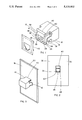
- FIG. 1 is a pictorial view showing the apparatus of the subject invention with the cover plate having been removed from the jack for clarity.
- FIG. 2 is a front elevational view of the jack of FIG. 1 with the jack having been inserted into a panel.
- FIG. 3 is a pictorial view of the jack of FIG. 1 with the jack having been inserted into a panel but showing the opposite side to that of FIG. 2.
- FIG. 4 is a side elevational view of the jack and cover plate of FIG. 1 but showing the cover plate attached to the jack and further showing the panel in phantom for clarity.
- FIG. 5 is a pictorial view of the cover plate shown in FIG. 1 showing the opposite side thereof.
- FIG. 6 is a partial top view of the apparatus of FIG. 4 showing one of the ears of the jack deflected by a certain amount due to a panel of one thickness.
- FIG. 7 shows the apparatus of FIG. 6 but with a panel of another thickness so that the ear is deflected by another amount.
- FIG. 8 shows the apparatus of the subject invention with three openings in the panel with the jacks and cover plates in various stages of assembly.
- FIG. 9 shows an alternative embodiment to the cover plate shown in FIG. 5.
- electrical connector jack 10 which includes cavity 12 for receiving a corresponding electrical plug (not shown).
- the dimensions of cavity 12 conform with Part 68 of the Regulations of the Federal Communications Commission.
- Jack 10 includes a pair of resilient ears 14 and 16 projecting therefrom in a curved fashion. Ears 14 and 16 form a first stop for contacting the backside 18 of panel 20 as shown in FIG. 3.
- Panel 20 may have various thicknesses and may take various forms such as, for example a wall, a face plate, a baseboard, modular furniture, or a patch panel.
- the ears 14 and 16 are made resilient by flaring out and curving them from jack 10.
- jack 10 may be moved in a range of distance into opening 22 in the panel 20, to the extent of the flexibility of ears 14 and 16, thereby enabling the jack to fit into openings of various thicknesses of panels.
- a jack having the resilient ears described above has been constructed enabling approximately a 1 mm movement of the jack within the opening in a panel.
- the invention is not limited to that range of movement.
- Jack 10 also includes a pair of beams 24 and 26 projecting therefrom which also form a stop.
- Beams 24 and 26 include a pair of ledges or hooks 28 and 30 extending from the free ends of the beams.
- the ledges 28 and 30 attach to front side 32 of panel 20 for securing jack 10 into opening 22 of the panel.
- Beams 24 and 26 are also resilient and are then able to move upwardly and downwardly so that they may snap fit into opening 22.
- Each of the ledges 28 and 30 of the beams include a ramp 32 which provides easier access into opening 22 of the panel by permitting beams 24 and 26 to ride upwardly as the ramps contact lower edge 34 of opening 22.
- each edge 36 of ledges 28 and 30 is located a predetermined horizontal distance, as measured along the longitudinal axis of the jack, from edge 38 of each of the ear 14 and 16 to the extent of the approximate thickness of panel 20.
- the horizontal distance between the two edges increases as the ears 14 and 16 increase flex.
- FIGS. 6 and 7. In FIG. 6 a thin panel 20(a) is used. The thickness of the panel 20(a) and the horizontal distance from edge 38 of ear 14 to edge 36 of ledge 28 is small as indicated by line 39.
- a thick panel 20(b) is used. The thickness of the panel 20(b) and the horizontal distance from edge 38 of ear 14 to edge 36 of ledge 28 is greater as indicated by line 41. Also ear 14 is flexed more for the thicker panel.
- Jack 10 also includes ledge 40 which also contacts outer wall 32 of panel 20 to aid in securing plug 10 into opening 22 of the panel.
- cover plate 42 is provided for aesthetic appeal by obscuring portions of jack 10 and further for locking jack 10 onto panel 20.
- Cover plate 42 includes opening 44 which is in the same shape as the opening for cavity 12 in jack 10. It is preferred that the color of the cover plate 42 be the same as the color of panel 20 or another color to identify the jack for a special purpose.
- jack 10 may come in a single color because the cover plate will substantially hide the jack thereby reducing the cost of producing the jack.
- cover plate 42 includes a first pair of posts 46 and 48 and a second pair of posts 50 and 52.
- Posts 46 and 48 are received in gaps 54 and 56 each of which is formed between one of the beams such as beam 24 and portion 56 of the jack.
- gap 54 the post forces resilient beam 24 downwardly thus securing the ledge or hook 28 onto the front side 32 of the panel 20.
- Studs 50 and 52 are received respectively in slots 60 and 62 of jack 10.
- FIG. 8 shows panel 20 with three openings 21, 23 and 25 therein with plugs 10(a), 10(b), and 10(c) and cover plates 42(a), 42(b), and 42(c) in various stages of assembly.
- FIG. 9 shows an alternative cover plate 60 which in addition to posts 46, 48, 50, and 52 includes a pair of tabs 62 and 64.
- Cover plate 60 would be used in situations for example where a six contact plug is to be connected to an eight contact jack. Tabs 62 and 64 are received in opening 12 of jack 10 and make contact with the outer contacts of the jack so that none of the contacts of the six contact plug would improperly make contact with the outer contacts.
- jack 10 is made even more versatile since a single eight contact jack may be used with eight, six, and even four contact jacks.
- an electrical connector jack which is universal in that it will fit varying thicknesses of panels and various types of panels and may be easily mounted to such panels by snap fitting the jack thereto without the need for special tools, and may be used with various sizes of plugs.
- the jack may be locked onto the panel by means of a cover plate which also provides an improved appearance.
Abstract
Description
Claims (14)
Priority Applications (1)
| Application Number | Priority Date | Filing Date | Title |
|---|---|---|---|
| US07/729,578 US5125852A (en) | 1991-07-15 | 1991-07-15 | Universal electrical connector jack |
Applications Claiming Priority (1)
| Application Number | Priority Date | Filing Date | Title |
|---|---|---|---|
| US07/729,578 US5125852A (en) | 1991-07-15 | 1991-07-15 | Universal electrical connector jack |
Publications (1)
| Publication Number | Publication Date |
|---|---|
| US5125852A true US5125852A (en) | 1992-06-30 |
Family
ID=24931664
Family Applications (1)
| Application Number | Title | Priority Date | Filing Date |
|---|---|---|---|
| US07/729,578 Expired - Lifetime US5125852A (en) | 1991-07-15 | 1991-07-15 | Universal electrical connector jack |
Country Status (1)
| Country | Link |
|---|---|
| US (1) | US5125852A (en) |
Cited By (33)
| Publication number | Priority date | Publication date | Assignee | Title |
|---|---|---|---|---|
| US5362254A (en) * | 1992-12-18 | 1994-11-08 | The Siemon Company | Electrically balanced connector assembly |
| EP0630077A2 (en) * | 1993-06-17 | 1994-12-21 | General DataComm, Inc. | Grounding spring clips for modular jacks |
| US5411414A (en) * | 1993-08-17 | 1995-05-02 | Premier Telecom Products, Inc. | Electrical connector |
| US5459643A (en) | 1993-09-30 | 1995-10-17 | The Siemon Company | Electrically enhanced wiring block with break test capability |
| US5487666A (en) * | 1991-12-31 | 1996-01-30 | Digiovanni; Thomas H. | Schematic patch panel |
| US5542859A (en) * | 1994-11-16 | 1996-08-06 | Woods Industries, Inc. | Quick mount electrical wall socket |
| US5647763A (en) * | 1995-02-09 | 1997-07-15 | Superior Modular Products Incorporated | Multi-media cross connect system |
| US5651696A (en) * | 1995-04-28 | 1997-07-29 | Jennison; Michael T. | CEBUS tap point unit |
| US6106330A (en) * | 1998-05-29 | 2000-08-22 | International Connectors And Cable Corporation | Adapter housing for connectors |
| US6283768B1 (en) | 1999-05-13 | 2001-09-04 | Ideal Industries, Inc. | RJ-45 style modular connector |
| US6420964B1 (en) * | 1999-03-25 | 2002-07-16 | Matsushita Electric Industrial Co., Ltd. | Informational outlet and lines collection module |
| US6616005B1 (en) * | 2000-08-28 | 2003-09-09 | Hubbell Incorporated | Modular faceplate assembly for an electrical box |
| US20040077213A1 (en) * | 2002-09-30 | 2004-04-22 | Fujikura Ltd. | Connecting structure for accessory device and cable, waterproofing structure for accessory device, and mounting structure for accessory device |
| US20060019533A1 (en) * | 2004-07-23 | 2006-01-26 | Yuan-Huei Peng | Bezel of modular jack |
| EP1544961A3 (en) * | 2003-12-17 | 2006-03-29 | Byrne Electrical Specialists, Inc. | Voice/data adapter kit |
| US20060134971A1 (en) * | 2004-12-17 | 2006-06-22 | Byrne Norman R | Voice/data adapter kit |
| US20070019669A1 (en) * | 2003-07-09 | 2007-01-25 | Serconet Ltd. | Modular outlet |
| US7318754B1 (en) | 2006-09-08 | 2008-01-15 | Superior Modular Products Incorporated | Keyed modular connection system and associated adapter cable |
| US20080062655A1 (en) * | 2006-09-08 | 2008-03-13 | Leviton Manufacturing Co., Inc. | Equipment rack panel system and method |
| US20080227333A1 (en) * | 2004-02-16 | 2008-09-18 | Serconet Ltd. | Outlet add-on module |
| US20080274640A1 (en) * | 2007-03-29 | 2008-11-06 | The Siemon Company | Telecommunications Connectors And Apparatus For Mounting The Same |
| US20100317223A1 (en) * | 2009-06-15 | 2010-12-16 | Byrne Norman R | Power and data adapter assembly |
| US8057249B1 (en) | 2010-07-19 | 2011-11-15 | Tyco Electronics Corporation | Electrical connector with slim-line cap |
| WO2012039949A1 (en) * | 2010-09-24 | 2012-03-29 | Ortronics, Inc. | High density jack |
| WO2012102948A1 (en) * | 2011-01-27 | 2012-08-02 | Commscope, Inc. Of North Carolina | Modular communications jack with user-selectable mounting |
| US8480429B2 (en) | 2005-06-13 | 2013-07-09 | Norman R. Byrne | Power data housing |
| US8672709B2 (en) | 2010-09-24 | 2014-03-18 | Ortronics, Inc. | High density jack |
| USD797545S1 (en) * | 2016-09-22 | 2017-09-19 | Crestron Electronics, Inc. | Wall mounted jack panel |
| USD799934S1 (en) * | 2016-09-22 | 2017-10-17 | Crestron Electronics, Inc. | Wall mounted receptacle |
| US9912102B1 (en) * | 2016-11-29 | 2018-03-06 | Leviton Manufacturing Co., Inc. | Limited power outlet with changeable protective bezel |
| WO2019072109A1 (en) * | 2017-10-13 | 2019-04-18 | 青岛海尔滚筒洗衣机有限公司 | Network port socket for use with washing machine and washing machine comprising network port socket |
| CN111029844A (en) * | 2019-12-30 | 2020-04-17 | 上海摩勤智能技术有限公司 | Charging device |
| US10770830B2 (en) * | 2017-01-16 | 2020-09-08 | Jrd Communication Inc. | Electronic product and USB cover connecting structure thereof |
Citations (3)
| Publication number | Priority date | Publication date | Assignee | Title |
|---|---|---|---|---|
| US3523269A (en) * | 1968-03-08 | 1970-08-04 | Essex International Inc | Panel locking terminal connector block |
| US4315664A (en) * | 1980-05-05 | 1982-02-16 | Amp Incorporated | Modular jack |
| US4602842A (en) * | 1984-12-03 | 1986-07-29 | Cts Corporation | Electrical connector receptacle |
-
1991
- 1991-07-15 US US07/729,578 patent/US5125852A/en not_active Expired - Lifetime
Patent Citations (3)
| Publication number | Priority date | Publication date | Assignee | Title |
|---|---|---|---|---|
| US3523269A (en) * | 1968-03-08 | 1970-08-04 | Essex International Inc | Panel locking terminal connector block |
| US4315664A (en) * | 1980-05-05 | 1982-02-16 | Amp Incorporated | Modular jack |
| US4602842A (en) * | 1984-12-03 | 1986-07-29 | Cts Corporation | Electrical connector receptacle |
Cited By (71)
| Publication number | Priority date | Publication date | Assignee | Title |
|---|---|---|---|---|
| US5487666A (en) * | 1991-12-31 | 1996-01-30 | Digiovanni; Thomas H. | Schematic patch panel |
| US5362254A (en) * | 1992-12-18 | 1994-11-08 | The Siemon Company | Electrically balanced connector assembly |
| US5435752A (en) | 1992-12-18 | 1995-07-25 | The Siemon Company | Electrically balanced connector assembly |
| US5474474A (en) | 1992-12-18 | 1995-12-12 | The Siemon Company | Electrically balanced connector assembly |
| EP0630077A2 (en) * | 1993-06-17 | 1994-12-21 | General DataComm, Inc. | Grounding spring clips for modular jacks |
| EP0630077A3 (en) * | 1993-06-17 | 1996-01-31 | Gen Datacomm Ind Inc | Grounding spring clips for modular jacks. |
| US5411414A (en) * | 1993-08-17 | 1995-05-02 | Premier Telecom Products, Inc. | Electrical connector |
| US5459643A (en) | 1993-09-30 | 1995-10-17 | The Siemon Company | Electrically enhanced wiring block with break test capability |
| US5542859A (en) * | 1994-11-16 | 1996-08-06 | Woods Industries, Inc. | Quick mount electrical wall socket |
| US5647763A (en) * | 1995-02-09 | 1997-07-15 | Superior Modular Products Incorporated | Multi-media cross connect system |
| US5651696A (en) * | 1995-04-28 | 1997-07-29 | Jennison; Michael T. | CEBUS tap point unit |
| US6106330A (en) * | 1998-05-29 | 2000-08-22 | International Connectors And Cable Corporation | Adapter housing for connectors |
| US6420964B1 (en) * | 1999-03-25 | 2002-07-16 | Matsushita Electric Industrial Co., Ltd. | Informational outlet and lines collection module |
| US6283768B1 (en) | 1999-05-13 | 2001-09-04 | Ideal Industries, Inc. | RJ-45 style modular connector |
| US6616005B1 (en) * | 2000-08-28 | 2003-09-09 | Hubbell Incorporated | Modular faceplate assembly for an electrical box |
| US20040077213A1 (en) * | 2002-09-30 | 2004-04-22 | Fujikura Ltd. | Connecting structure for accessory device and cable, waterproofing structure for accessory device, and mounting structure for accessory device |
| US7901219B2 (en) * | 2002-09-30 | 2011-03-08 | Fujikura Ltd. | Connecting structure for accessory device and cable, waterproofing structure for accessory device, and mounting structure for accessory device |
| US20070019669A1 (en) * | 2003-07-09 | 2007-01-25 | Serconet Ltd. | Modular outlet |
| US7688841B2 (en) | 2003-07-09 | 2010-03-30 | Mosaid Technologies Incorporated | Modular outlet |
| US7873062B2 (en) | 2003-07-09 | 2011-01-18 | Mosaid Technologies Incorporated | Modular outlet |
| US7867035B2 (en) | 2003-07-09 | 2011-01-11 | Mosaid Technologies Incorporated | Modular outlet |
| US8360810B2 (en) | 2003-09-07 | 2013-01-29 | Mosaid Technologies Incorporated | Modular outlet |
| US8235755B2 (en) | 2003-09-07 | 2012-08-07 | Mosaid Technologies Incorporated | Modular outlet |
| US8591264B2 (en) | 2003-09-07 | 2013-11-26 | Mosaid Technologies Incorporated | Modular outlet |
| US8092258B2 (en) | 2003-09-07 | 2012-01-10 | Mosaid Technologies Incorporated | Modular outlet |
| US7690949B2 (en) | 2003-09-07 | 2010-04-06 | Mosaid Technologies Incorporated | Modular outlet |
| US7686653B2 (en) | 2003-09-07 | 2010-03-30 | Mosaid Technologies Incorporated | Modular outlet |
| EP1544961A3 (en) * | 2003-12-17 | 2006-03-29 | Byrne Electrical Specialists, Inc. | Voice/data adapter kit |
| US7756268B2 (en) | 2004-02-16 | 2010-07-13 | Mosaid Technologies Incorporated | Outlet add-on module |
| US8542819B2 (en) | 2004-02-16 | 2013-09-24 | Mosaid Technologies Incorporated | Outlet add-on module |
| US20080227333A1 (en) * | 2004-02-16 | 2008-09-18 | Serconet Ltd. | Outlet add-on module |
| US8243918B2 (en) | 2004-02-16 | 2012-08-14 | Mosaid Technologies Incorporated | Outlet add-on module |
| US8611528B2 (en) | 2004-02-16 | 2013-12-17 | Mosaid Technologies Incorporated | Outlet add-on module |
| US8565417B2 (en) | 2004-02-16 | 2013-10-22 | Mosaid Technologies Incorporated | Outlet add-on module |
| US7881462B2 (en) | 2004-02-16 | 2011-02-01 | Mosaid Technologies Incorporated | Outlet add-on module |
| US7131864B2 (en) * | 2004-07-23 | 2006-11-07 | Yuan-Huei Peng | Bezel of modular jack |
| US20060019533A1 (en) * | 2004-07-23 | 2006-01-26 | Yuan-Huei Peng | Bezel of modular jack |
| US7182633B2 (en) * | 2004-12-17 | 2007-02-27 | Byrne Norman R | Voice/data adapter kit |
| US20060134971A1 (en) * | 2004-12-17 | 2006-06-22 | Byrne Norman R | Voice/data adapter kit |
| US8480429B2 (en) | 2005-06-13 | 2013-07-09 | Norman R. Byrne | Power data housing |
| US20100314339A1 (en) * | 2006-09-08 | 2010-12-16 | Leviton Manufacturing Co., Inc. | Equipment rack panel system and method |
| US7594829B2 (en) | 2006-09-08 | 2009-09-29 | Superior Modular Products, Incorporated | Keyed modular connection system and associated adapter cable |
| US8061534B2 (en) * | 2006-09-08 | 2011-11-22 | Leviton Manufacturing Co., Inc. | Equipment rack panel system and method |
| US8038015B2 (en) * | 2006-09-08 | 2011-10-18 | Leviton Manufacturing Co., Ltd. | Equipment rack panel system and method |
| US7318754B1 (en) | 2006-09-08 | 2008-01-15 | Superior Modular Products Incorporated | Keyed modular connection system and associated adapter cable |
| US20080062655A1 (en) * | 2006-09-08 | 2008-03-13 | Leviton Manufacturing Co., Inc. | Equipment rack panel system and method |
| US20080113562A1 (en) * | 2006-09-08 | 2008-05-15 | Superior Modular Products Incorporated | Keyed modular connection system and associated adapter cable |
| US20100099297A1 (en) * | 2007-03-29 | 2010-04-22 | The Siemon Company | Telecommunication Connectors And Apparatus For Mounting The Same |
| US20080274640A1 (en) * | 2007-03-29 | 2008-11-06 | The Siemon Company | Telecommunications Connectors And Apparatus For Mounting The Same |
| US7651369B2 (en) * | 2007-03-29 | 2010-01-26 | The Siemon Company | Telecommunications connectors and apparatus for mounting the same |
| US8162692B2 (en) | 2007-03-29 | 2012-04-24 | The Siemon Company | Telecommunication connectors and apparatus for mounting the same |
| US8444432B2 (en) | 2009-06-15 | 2013-05-21 | Norman R. Byrne | Power and data adapter assembly |
| US20100317223A1 (en) * | 2009-06-15 | 2010-12-16 | Byrne Norman R | Power and data adapter assembly |
| US8057249B1 (en) | 2010-07-19 | 2011-11-15 | Tyco Electronics Corporation | Electrical connector with slim-line cap |
| US8628351B2 (en) | 2010-09-24 | 2014-01-14 | Ortronics, Inc. | High density jack |
| CN103229367A (en) * | 2010-09-24 | 2013-07-31 | 奥创利公司 | High density jack |
| WO2012039949A1 (en) * | 2010-09-24 | 2012-03-29 | Ortronics, Inc. | High density jack |
| US8439702B2 (en) | 2010-09-24 | 2013-05-14 | Ortronics, Inc. | High density jack |
| US8672709B2 (en) | 2010-09-24 | 2014-03-18 | Ortronics, Inc. | High density jack |
| US8715002B2 (en) | 2011-01-27 | 2014-05-06 | Commscope, Inc. Of North Carolina | Modular communications jack with user-selectable mounting |
| WO2012102948A1 (en) * | 2011-01-27 | 2012-08-02 | Commscope, Inc. Of North Carolina | Modular communications jack with user-selectable mounting |
| USD818799S1 (en) * | 2016-09-22 | 2018-05-29 | Crestron Electronics, Inc. | Wall mounted jack panel |
| USD797545S1 (en) * | 2016-09-22 | 2017-09-19 | Crestron Electronics, Inc. | Wall mounted jack panel |
| USD799934S1 (en) * | 2016-09-22 | 2017-10-17 | Crestron Electronics, Inc. | Wall mounted receptacle |
| USD818800S1 (en) * | 2016-09-22 | 2018-05-29 | Crestron Electronics, Inc. | Wall mounted receptacle |
| US9912102B1 (en) * | 2016-11-29 | 2018-03-06 | Leviton Manufacturing Co., Inc. | Limited power outlet with changeable protective bezel |
| US20180159272A1 (en) * | 2016-11-29 | 2018-06-07 | Leviton Manufacturing Co., Inc. | Limited power outlet with changeable protective bezel |
| US10355433B2 (en) * | 2016-11-29 | 2019-07-16 | Leviton Manufacturing Co., Inc. | Limited power outlet with changeable protective bezel |
| US10770830B2 (en) * | 2017-01-16 | 2020-09-08 | Jrd Communication Inc. | Electronic product and USB cover connecting structure thereof |
| WO2019072109A1 (en) * | 2017-10-13 | 2019-04-18 | 青岛海尔滚筒洗衣机有限公司 | Network port socket for use with washing machine and washing machine comprising network port socket |
| CN111029844A (en) * | 2019-12-30 | 2020-04-17 | 上海摩勤智能技术有限公司 | Charging device |
Similar Documents
| Publication | Publication Date | Title |
|---|---|---|
| US5125852A (en) | Universal electrical connector jack | |
| US5562493A (en) | Network interface assembly and mounting frame | |
| US5041018A (en) | Electrical connector receptacle | |
| US5238426A (en) | Universal patch panel for communications use in buildings | |
| US6180878B1 (en) | Electrical outlet raceway | |
| US6257922B1 (en) | Connector | |
| US6616005B1 (en) | Modular faceplate assembly for an electrical box | |
| EP1376800B1 (en) | Quick connecting universal electrical box and wiring system | |
| US4059327A (en) | Recessed electrical outlet | |
| US5044981A (en) | Snap-on stacking telephone jack | |
| GB1599854A (en) | Electrical connector mounting apparatus | |
| US11342718B2 (en) | Latch for telecommunications connector | |
| GB1567912A (en) | Spacedividing wall systems | |
| US7602619B2 (en) | Support frame and group of parts for wall mounting an electrical apparatus | |
| US4863399A (en) | Low voltage bracket | |
| EP1049211B1 (en) | Multi-piece connector | |
| US5700978A (en) | Snap-together wall plates for ganged electrical device installations | |
| US4715827A (en) | Modular connector system | |
| US5830008A (en) | Panel mountable connector | |
| US6210217B1 (en) | Electrical connector system having a connector mounted on a conductive panel | |
| US4641900A (en) | Telephone distribution apparatus | |
| AU665871B2 (en) | Jack socket assembly | |
| US4154498A (en) | Removable electrical connector | |
| US4863398A (en) | Universal adapter for office wall panels | |
| US5921643A (en) | Zero clearance locating and connecting pin and connecting system using same |
Legal Events
| Date | Code | Title | Description |
|---|---|---|---|
| AS | Assignment |
Owner name: SUPERIOR TELETEC TRANSMISSION PRODUCTS, INC. A Free format text: ASSIGNMENT OF ASSIGNORS INTEREST.;ASSIGNOR:ARCHER, LEE A.;REEL/FRAME:005778/0156 Effective date: 19910709 |
|
| AS | Assignment |
Owner name: SUPERIOR MODULAR PRODUCTS, INC. A CORPORATION OF Free format text: ASSIGNMENT OF ASSIGNORS INTEREST.;ASSIGNOR:SUPERIOR TELE TEC TRANSMISSION PRODUCTS, INC., A GA CORPORATION;REEL/FRAME:006072/0972 Effective date: 19920403 |
|
| STCF | Information on status: patent grant |
Free format text: PATENTED CASE |
|
| AS | Assignment |
Owner name: SUPERIOR MODULAR PRODUCTS INCORPORATED, A DE COR Free format text: ASSIGNMENT OF ASSIGNORS INTEREST;ASSIGNOR:SUPERIOR MODULAR PRODUCTS, INC. A NORTH CAROLINA CORP.;REEL/FRAME:006783/0775 Effective date: 19931203 |
|
| FEPP | Fee payment procedure |
Free format text: PAT HLDR NO LONGER CLAIMS SMALL ENT STAT AS SMALL BUSINESS (ORIGINAL EVENT CODE: LSM2); ENTITY STATUS OF PATENT OWNER: LARGE ENTITY |
|
| FEPP | Fee payment procedure |
Free format text: PAYOR NUMBER ASSIGNED (ORIGINAL EVENT CODE: ASPN); ENTITY STATUS OF PATENT OWNER: LARGE ENTITY |
|
| FPAY | Fee payment |
Year of fee payment: 4 |
|
| FPAY | Fee payment |
Year of fee payment: 8 |
|
| FPAY | Fee payment |
Year of fee payment: 12 |
|
| REMI | Maintenance fee reminder mailed | ||
| AS | Assignment |
Owner name: OPTICAL CABLE CORPORATION,VIRGINIA Free format text: MERGER;ASSIGNOR:SUPERIOR MODULAR PRODUCTS INCORPORATED;REEL/FRAME:023957/0502 Effective date: 20091031 Owner name: OPTICAL CABLE CORPORATION, VIRGINIA Free format text: MERGER;ASSIGNOR:SUPERIOR MODULAR PRODUCTS INCORPORATED;REEL/FRAME:023957/0502 Effective date: 20091031 |