US5125533A - Variable blending dispenser - Google Patents
Variable blending dispenser Download PDFInfo
- Publication number
- US5125533A US5125533A US07/656,739 US65673991A US5125533A US 5125533 A US5125533 A US 5125533A US 65673991 A US65673991 A US 65673991A US 5125533 A US5125533 A US 5125533A
- Authority
- US
- United States
- Prior art keywords
- dispenser
- supply lines
- fluid supply
- blend
- amount
- Prior art date
- Legal status (The legal status is an assumption and is not a legal conclusion. Google has not performed a legal analysis and makes no representation as to the accuracy of the status listed.)
- Expired - Lifetime
Links
Images


Classifications
-
- B—PERFORMING OPERATIONS; TRANSPORTING
- B67—OPENING, CLOSING OR CLEANING BOTTLES, JARS OR SIMILAR CONTAINERS; LIQUID HANDLING
- B67D—DISPENSING, DELIVERING OR TRANSFERRING LIQUIDS, NOT OTHERWISE PROVIDED FOR
- B67D7/00—Apparatus or devices for transferring liquids from bulk storage containers or reservoirs into vehicles or into portable containers, e.g. for retail sale purposes
- B67D7/06—Details or accessories
- B67D7/74—Devices for mixing two or more different liquids to be transferred
- B67D7/743—Devices for mixing two or more different liquids to be transferred electrically or electro-mechanically operated
- B67D7/744—Devices for mixing two or more different liquids to be transferred electrically or electro-mechanically operated involving digital counting
-
- G—PHYSICS
- G05—CONTROLLING; REGULATING
- G05D—SYSTEMS FOR CONTROLLING OR REGULATING NON-ELECTRIC VARIABLES
- G05D11/00—Control of flow ratio
- G05D11/02—Controlling ratio of two or more flows of fluid or fluent material
- G05D11/13—Controlling ratio of two or more flows of fluid or fluent material characterised by the use of electric means
- G05D11/131—Controlling ratio of two or more flows of fluid or fluent material characterised by the use of electric means by measuring the values related to the quantity of the individual components
- G05D11/132—Controlling ratio of two or more flows of fluid or fluent material characterised by the use of electric means by measuring the values related to the quantity of the individual components by controlling the flow of the individual components
-
- B—PERFORMING OPERATIONS; TRANSPORTING
- B67—OPENING, CLOSING OR CLEANING BOTTLES, JARS OR SIMILAR CONTAINERS; LIQUID HANDLING
- B67D—DISPENSING, DELIVERING OR TRANSFERRING LIQUIDS, NOT OTHERWISE PROVIDED FOR
- B67D7/00—Apparatus or devices for transferring liquids from bulk storage containers or reservoirs into vehicles or into portable containers, e.g. for retail sale purposes
- B67D7/06—Details or accessories
- B67D7/74—Devices for mixing two or more different liquids to be transferred
- B67D2007/745—Devices for mixing two or more different liquids to be transferred for obtaining fuel of a given octane level
- B67D2007/746—Devices for mixing two or more different liquids to be transferred for obtaining fuel of a given octane level by mixing different fuel grades or fuel and oil
Definitions
- the field of the invention is that of blending dispensers for liquids. More particularly, the field is that of blending dispensers capable of dispensing a variety of blending mixes.
- liquid dispensing devices for example gasoline fuel pumps
- different grades of gasolines are conventionally mixed to provide a specific blend.
- a dispenser can produce gasoline blends having a desired octane rating in the range of 83 to 95.
- the following example uses 83 and 95 octane gasolines as the component fuels because they represent a common prior art range of octanes; however, a variety of ranges of octanes have been used to mix and provide blends of gasoline.
- gasolines of various octane ratings can be provided by mixing component gasolines in the following percentages:
- a proportional control system has been used to check the blending ratio periodically by observing the instantaneous flow rates of the two component streams of fluid (e.g. from the 83 and 95 octane tanks).
- An electronic controller observes the instantaneous flow rates by receiving signals from pressure sensors coupled to the two flow lines.
- the valves which control the component streams are adjusted accordingly.
- This results in a dispenser which tends to deliver an instantaneous blend ratio equal to the desired mixture only after a significant portion of the desired quantity of fuel has been dispensed, assuming that liquid pressure remains relatively constant.
- a significant quantity of the dispensed fuel may have an incorrect blend or mixture.
- such proportional control systems only correct for errors in the instantaneous flow rate and do not account for the total errors in fuel which has already been dispensed so that the total amount of dispensed fuel will be a desired blend.
- the initial disparity does not enter into the calculation of the instantaneous rates, so that the total quantity of dispensed fuel for the session contains less than the desired 50% of 83 octane fuel.
- a steady state error exists created by the initial mixture which contained substantially more 95 octane fuel than 83 octane fuel.
- the steady state error represents that amount of 95 octane gasoline which exceeds the amount of 83 octane gasoline, and the error can never be eliminated because the instantaneous rates are maintained at the 50% ratio.
- the cumulative blend ratio does approach the desired cumulative ratio as the amount of fuel dispensed approaches infinity, but the average consumer does not dispense such a large volume of fuel, rather the typical volume of gasoline dispensed by a consumer is between five and ten gallons.
- the steady state error does not substantially decrease for gasoline dispensing applications because of the low volume of dispensing.
- small quantities of dispensed fuel tend to have large errors.
- random fluctuations of pressure within the proportional control system can add to the steady state error.
- the dispenser provided 5.3 gallons of 95 octane gasoline compared to 4.7 gallons of 83 octane gasoline, resulting in a cumulative blend ratio of 4.7/(4.7+5.3) or 47%.
- the system then corrected for the pressure differential and dispensed an approximately 50% blend ratio.
- the dispenser provided 5.5 gallons of 95 octane gasoline compared to 4.5 gallons of 83 octane gasoline, resulting in a cumulative blend ratio of 4.5/(4.5+5.5) or 45%.
- One form of prior art dispenser uses fixed orifice valves with pressure equalizers to achieve proper blending, generally having a cumulative accuracy of approximately 3%.
- the size of the orifice for each gasoline determines the instantaneous blend because the pressures are maintained relatively equal by pressure equalizers.
- to provide a blend which does not correspond to specific orifice sizes requires that the valves of the dispenser must be periodically turned on and off. Because the pressure sensors, valves, and pressure equalizers of dispensers are least accurate during starting and stopping, using fixed orifice blenders limits the versatility of the blending dispensers.
- pressure equalizers In dispensing operations having more than one dispenser for each pair of tanks, which is the usual circumstance, pressure equalizers often cannot perform adequately because of the variable pressures from the supplying tanks. For example, if three dispensers are currently dispensing 95 octane gasoline, and then a fourth dispenser is set to provide 89 octane gasoline, the fluid pressure in the supply line from the 95 octane supply tank should be substantially less than the pressure from the 83 octane supply tank. The resulting imbalance between pressures causes imprecision in accurately providing the desired cumulative blend.
- dispensers tabulate the total amount dispensed, not the individual amounts dispensed from each tank. This can present difficulty to sellers of gasoline who must accurately measure the amount of gasoline withdrawn from each supply tank. Although an estimate of the individual amounts withdrawn are made from the total amount dispensed, additional proving must occur to verify the estimated amounts. Further, to insure that the desired cumulative blend is produced so the octane rating is at least as high as desired, the dispenser is biased in favor of dispensing more of the higher octane, more expensive gasoline.
- Another feature of gasoline dispensers is that the operator may choose to dispense the gasoline quickly or slowly by actuating the nozzle handle.
- the operator can control the nozzle of the dispenser to change the flow rate or turn the flow on or off at any time. Due to the unpredictability of the operation of the nozzle, the signals sent by the pressure sensors may differ greatly at different times. When the nozzle is off, no flow exists, and the periodic signals sent by the pressure sensors may not present adequate information to make an accurate blend calculation. Thus, prior art dispensers have further problems due to erratic and unpredictable use which further impairs their accuracy.
- the present invention is a variable blending dispenser.
- Variable valves are controlled to provide improved accuracy in a blending dispenser.
- the valves are corrected successively after having dispensed a threshold volume. The correction required is calculated on the basis of the volumes of component fluids dispensed, so that the total amount dispensed of each blend component is measured.
- variable blends are efficiently and accurately dispensed.
- the control microprocessor of the dispenser checks the amount dispensed once per predetermined time period, but only when a predetermined threshold volume has been dispensed does it perform an error correction.
- the blend ratio is defined as the ratio, expressed as a percent, of the volume of one of the products dispensed to the total volume of the two products dispensed.
- the error is calculated by comparing the blend ratio based on the actual volumes dispensed to the desired blend ratio.
- the present invention is adaptable to a variety of sizes of installations, from one dispenser and two small tanks to a multiplicity of dispensers and two or more large tanks.
- the calibration of the dispenser is not dependent upon the size of its installation, the only dynamically set parameters are the desired cumulative blend ratio and, optionally, the amount of fuel.
- the present invention is more accurate than "fixed orifice" blenders because it uses the cumulative volume, that is the volume dispensed since the beginning of the dispensing session, rather than rate to adjust the blend dispensed. Also, piston meters which determine the measurements of the amount of flow are accurate at both slow and fast flow, compared to the accuracy of pressure sensors. While pressure sensor systems require continuous adjustment when the nozzle is turned on and off for short time intervals, the dispenser of the present invention waits a predetermined time before adjusting the valves when the nozzle is intermittently activated. The blending valve of the present invention also functions as the shut off valve.
- the present invention minimizes wear on valves because only one valve is variably controlled.
- the present invention maintains one valve fully open and dynamically adjusts the other valve to provide the desired blend ratio.
- the volume flow through the conduits and the desired blend ratio determine which valve fully opens.
- the error correction of the present invention takes into account present and past volumes dispensed using a proportional-integral-differential (PID) adjustment algorithm.
- PID proportional-integral-differential
- This PID algorithm bases any error correction on the present (instantaneous) blend position of the valves, the cumulative blend ratio, and the most recent changes to the instantaneous blend ratio.
- the present invention in one form thereof, is a dispenser for blending component fluids according to a desired cumulative blend ratio. It comprises fluid conduits, valves, flow meters, an output device, and a control device.
- the fluid conduits are coupled to supplies of component fluids which are to be dispensed.
- the valves control the flow rate at which component fluids flow through the conduits.
- the flow meters are connected to the valves for measuring the volume of component fluid flowing through each conduit and for providing a volume signal.
- the output device mixes and dispenses the component fluids.
- the control device controls the blending and dispensing of the component fluids by measuring the volume dispensed with the flow meters and by controlling the volume dispensed with the valves.
- a comparison device of the control device is used to determine a corrected blend ratio, and a selection device of the control device is used to specify the desired blend ratio.
- the control device also includes an adjustment device which adjusts the valves in accordance with the corrected blend ratio so the ratio of dispensed fluids is equal to the desired ratio.
- One object of the present invention is to provide a dispenser which provides an accurate blend.
- An additional object is to provide a dispenser which accurately measures the component fluids of the blend dispensed.
- a further object of the present invention is to provide a dispenser which calculates valve adjustments according to the cumulative volumes of component fluids dispensed.
- an object of the present invention is to provide a dispenser which uses a PID algorithm to mix and dispense a desired blend.
- Yet another object of the present invention is to provide a blending dispenser which does not require a separate shut-off valve.
- an object of the present invention is to replace fixed orifice valves with variable valves and pressure sensors with positive displacement piston meters in a dispenser to more accurately measure flow and minimize wear on the valves.
- FIG. 1 is a schematic diagram of the variable blending dispenser of the present invention
- FIG. 2 is a diagram of the preferred embodiment
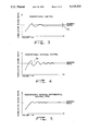
- FIGS. 3-5 are graphs of cumulative blend ratio plotted in relation to volume for proportional control, proportional-integral control, and proportional-integral-differential control;
- FIG. 6 is a graph of total volume plotted in relation to time showing threshold points of checking and correction.
- FIGS. 7 and 8 are flow-charts of the operation of the present invention.
- Dispenser unit 8 of the present invention is depicted in FIG. 1.
- Controller board 10 receives signals from pulsers 12 and 14 and operates variable valves 16 and 18.
- Nozzle 20, via Y connection 22, receives the output of variable valves 16 and 18, mixing and dispensing the component fluids.
- Variable valve 16 receives its input from supply tank 24, with meter 26 monitoring the volume of fluid supplied to variable valve 16.
- Pulser 12 is coupled to meter 26 and sends pulses to controller board 10 which represent the volume of fuel flow through valve 16.
- supply tank 28 provides fluid input to variable valve 18, with meter 30 measuring the volume of fluid flow through valve 18 and electronically transmitting that volume to controller board 10 via pulser 14.
- the functions of valves 16 and 18 can be combined in a single valve in which one passageway opens while the other closes.
- Dispenser unit 32 has two sets of supply tanks, meters, and valves coupled to an output nozzle. Specifically, supply tanks 34 and 36 are coupled to meters 38 and 40, respectively.
- supply tank 34 contains low octane gasoline (Product 1, e.g. 83 octane) and supply tank 36 contains a high octane gasoline (Product 2, e.g. 95 octane).
- Each of meters 38 and 40 which in the preferred embodiment are positive displacement meters such as piston meters, measures the volume of gasoline supplied by its respective supply tank, and are coupled to pulsers 42 and 44, respectively.
- controller board 45 To keep a count of the volume of gasoline measured by the respective meters, registers within controller board 45 count pulses received from pulsers 42 and 44 attached to meters 38 and 40. Each pulse represents a predetermined amount of fuel.
- Variable valve devices 46 and 48 serve as conduits between supply tanks 34 and 36, respectively, and Y connection 50 to provide nozzle 51 with appropriate volumes of component gasolines.
- Each variable valve device, 46 and 48 comprises an input solenoid valve 52, output solenoid valve 54, and a bellows valve 56.
- the bellows valve 56 comprises and an auxiliary chamber 55, spring 58, and plunger 59 which extends from chamber 55 to opening 57.
- the position of plunger 59 of bellows valve 56 determines the volume of fluid allowed to pass to Y connection 50, with the amount of liquid trapped in auxiliary chamber 55 determining the position of plunger 59.
- the amount of fluid trapped in auxiliary chamber 55 is manipulated by solenoids 52 and 54.
- One end of input solenoid 52 is connected at 51 to supply tank 34 or 36 near the input side of opening 57 of bellows valve 56 and one end of output solenoid 54 is connected at 53 to Y connection 50 near the output side of opening 57 of bellows valve 56.
- Auxiliary chamber 55 of bellows valve 56 connects the other ends of solenoids 52 and 54.
- Both solenoids 52 and 54 are pulse length activated, remaining open only during the receipt of a pulse signal. Thus the valve stays open longer for longer pulses. If input solenoid 52 is independently opened, fuel enters auxiliary chamber 55 and increases its internal pressure to push down plunger 59 and increase the fuel flow through opening 57 from its associated supply tank to Y connection 50. If output solenoid 54 is independently opened, fuel escapes from auxiliary chamber 55, decreasing its internal pressure allowing spring 58 to force plunger 59 upward to restrict flow through opening 57. When both solenoids 52 and 54 are open, the resulting fuel flow closes opening 57, so the only flow between supply tanks 34 or 36 and Y connection 50 is through solenoid 52, auxiliary chamber 55, and solenoid 54.
- auxiliary chamber 55 By controlling the amount of fuel in auxiliary chamber 55, the volume of fuel allowed to pass through valves 46 and 48 to nozzle 51 is accurately controlled. In addition, by keeping input solenoid 52 closed and output solenoid 54 open, auxiliary chamber 55 remains empty so plunger 59 blocks all flow through opening 57, thus making valves 46 and 48 capable of full shut-off. A separate shut-off valve is not needed, which simplifies the design and lowers the cost of manufacture.
- a microprocessor within controller board 45 is electrically coupled to pulsers 42 and 44.
- the microprocessor sends pulse signals of predetermined lengths to the solenoids of variable valve devices 46 and 48 based on conditions including the number of pulses received from pulsers 42 and 44, the desired blend ratio, and the desired volume to be dispensed.
- a method for evaluating and correcting the instantaneous flow rates is the PID algorithm, which stands for Proportional-Integral-Differential algorithm. Error at time t is defined as the difference between the observed ratio and the desired ratio, and is denoted e(t).
- the PID algorithm calculates a number on which to initiate correction actions, based on a combination of factors which are proportional (P), integral (I), and differential (D) of the error.
- K p , K i , and K d are constants which are determined empirically and optimized.
- the first component of m(t p ), the instantaneous blend ratio (P), is a function of the instantaneous error at time t p .
- the second component, the cumulative blend ratio (I), is a function of the integral summation of the error function values from the beginning of the current session to time t p .
- the third component, the difference from the previous instantaneous blend ratio (D), is a function of the derivative of the error function at time t p ; this differential is calculated as the difference between two successive instantaneous blend ratios divided by the size of the time interval.
- the time based PID algorithm is difficult to implement for blending since if in a short time interval relatively little fuel is dispensed, the calculated blend ratio is highly inaccurate.
- the microprocessor of the present invention uses a volume based PID control algorithm to control the solenoid valves 52 and 54.
- the volume based PID algorithm is similar to the time based PID algorithm, except that volume is the independent variable.
- K p , K i , and K d are constants which are determined empirically and optimized.
- the independent variable v represents the total volume of dispensed liquids, with that information stored in controller board 45.
- the error function is calculated using a desired blend ratio which is also stored in controller board 45.
- the first component (P) of m(v p ) is a factor of the instantaneous blend error at volume v p , calculated as the instantaneous blend ratio minus the desired ratio.
- the second component (I) is a factor of the integral summation of the instantaneous blend error values from the beginning of the current session to volume v p . In the present invention, the integral is evaluated by subtracting the cumulative blend ratio from the desired blend ratio.
- the third component (D) is a factor of the derivative of the error function at volume v p , calculated as the difference between the instantaneous blend ratio error and the previous instantaneous blend ratio error, divided by the magnitude of the volume interval.
- the average accuracy of the blending is to within 0.3%. In a service station with potentially severe fluctuations in pressure, product flow, or other external conditions, the accuracy may fluctuate to a greater extent.
- FIGS. 3, 4, and 5 are graphs which show the performance of a volume based proportional control algorithm, a volume based proportional-integral algorithm, and a volume based PID algorithm, respectively.
- the horizontal axis represents volume and the vertical axis represents the cumulative percentage blend ratio, with the point marked on the vertical axis representing the desired blend ratio.
- volume is dependent upon time, time increases from left to right on the graphs.
- flow rate and conditions e.g., temperature, operator control, and pressure.
- the present invention achieves its advantages because the values are controlled by reference to volume, rather than time.
- the blend ratio is defined to be the volume of a product (e.g. Product 1) divided by the volume of combined products dispensed (e.g. Produce 1+Produce 2).
- Product 1 a product
- Product 2 the volume of combined products dispensed
- the first measure of the blend ratio occurs some time after zero and steadily increases until it gets to around the desired ratio. After a few oscillations, the cumulative blend ratio curve steadies at a percentage slightly below the desired ratio, creating steady state error 70.
- the cumulative blend ratio curve has a number of oscillations 72 around the desired blend which eventually settles to nearly exactly the desired blend.
- the cumulative blend ratio curve of the volume based PID algorithm settles at the desired ratio almost immediately, without any major oscillations or steady state error.
- the volume based PID algorithm achieves a uniform blending ratio relatively quickly, without a substantial period of oscillation or steady state error.
- Operation begins at initialization step 74 by zeroing the counters (Pulses1 for Product 1, and Pulses2 for Product 2) and initialization the CHECK, RATIO, and AMOUNT variables.
- the registers of the meters are not reset, rather the microprocessor records their beginning values and calculates the current values of the variables Pulses1 and Pulses2 as a function of the current register value compared to the initial register value. Normally, this computation is the difference between the two values, however, the registers do roll-over at a certain point, and this roll-over must be accounted for in software.
- the flow chart of FIG. 6 uses a zeroing of counters.
- the variable CHECK represents the accumulated volume at which the PID algorithm is executed to adjust the valves.
- CHECK is initialized at 40 so that at least 40 pulses must be counted by the registers before performing the PID algorithm, which at 1,000 pulses per gallon represents 1/25th of a gallon.
- the variable RATIO represents the percentage blend desired in the current dispensing session. This value is received as an input from the operator of the dispenser, e.g., when the customer presses a button selecting a particular desired blend of fuel.
- the variable AMOUNT represents the volume of fuel desired to be dispensed. Conventionally, the operator enters the dollar amount of gasoline desired, and the microprocessor converts the dollar amount to a volume.
- the pump When the total number of pulses equals the number of pulses represented by AMOUNT, the pump is shut off. Also, the operator can omit entering a desired amount, in which case the dispenser will continue to operate until the nozzle is closed and the pump is manually shut off. In this case, the steps in FIG. 7 which compare the number of pulses (Pulses 1+Pulses2) to the desired amount (AMOUNT) are omitted.
- the dispenser begins supplying fuel at slow flow 1, step 76.
- step 76 input and output solenoids 52 and 54 are both open so that fuel flows through auxiliary chamber 55 and not through opening 57 of bellows valve 56.
- One or the other set of solenoid valves (52 and 54) is alternately opened in order to maintain the desired blend ratio during slow flow.
- fast flow step 78 This is also termed "proportional flow” or "variable fast flow”.
- Fast flow 78 is accomplished by closing both solenoids 52 and 54 in order to trap liquid in auxiliary chamber 55, thus fixing the location of plunger 59.
- Bellows valve 56 is adjusted by opening either solenoid 52 or 54 for a short period of time to allow the size of auxiliary chamber 55 to change until plunger 59 is in the desired position. Then when solenoids 52 and 54 are closed, liquid is trapped in auxiliary chamber 55, keeping plunger 59 at the desired position to control the area of opening 57 not blocked by plunger 59 and thus keeping the amount of flow steady. After this, the flow may be increased by opening input solenoid 52 for a short period of time, or decreased by opening output solenoid 54 for a short period of time.
- valve device 48 coupled to the supply tank (e.g. valve device 46) of the higher percentage component fluid is opened fully, and the other valve device (e.g. valve device 48) is then adjusted proportionally.
- the microprocessor may determine that valve device 48 connected to the lower percentage component fluid supply tank should be kept fully open and valve device 46 should be adjusted proportionally. In either case, the non-fully open valve is adjusted so that the desired blend ratio is achieved.
- step 80 the microprocessor performs offset check step 80.
- the total number of pulses (Pulses1+Pulses2) is compared with the number of pulses needed for the desired amount minus some offset value, which in the preferred embodiment is 50 pulses. If the total number of pulses is less than AMOUNT-50, stop check step 82 is executed.
- step 82 the microprocessor determines whether any additional pulses have been detected since the immediately previous commencement of fast flow step 78. If the microprocessor determines that additional pulses have been detected, then the microprocessor commences fast flow step 78. Alternatively, if the microprocessor determines the pulses have stopped, then it recommences slow flow 1 step 76.
- the microprocessor returns to slow flow 1 step 76 from stop check step 82 only after 5 to 10 seconds have transpired since the last pulse. This additional delay accounts for times when the operator of the nozzle will intermittently turn on and off the liquid flow.
- step 84 slow flow is accomplished by opening both inlet and outlet solenoids 52 and 54 at the same time, thereby allowing liquid to flow through auxiliary chamber 55.
- Solenoids 52 and 54 with auxiliary chamber 55 provide a passageway to maintain a flow rate of 1.0 gallon per minute under expected pressure conditions. Slow flow is alternated between valves 46 and 48 as needed to maintain the desired blend ratio.
- end check step 86 is executed by the microprocessor.
- step 86 the total pulses (Pulses1+Pulses2) is compared to AMOUNT. If the total is less than the desired amount, the microprocessor recommences slow flow to step 84. If the total number of pulses equals or exceeds the desired amount, dispenser shut off step 88 is executed which ends the current session of fuel dispensing.
- the microprocessor executes an error correction routine.
- error correction is performed successively after having dispensed predetermined threshold volumes.
- the first threshold volume is after 40 pulses are received, and the microprocessor performs the first error correction.
- threshold volumes are after every 40 additional pulses, with the microprocessor executing the error correction routine after reaching each threshold.
- Total volume curve 104 represents the sum of Pulses1 and Pulses2 plotted against time in 100 msec intervals.
- Timer interrupt points 106 along curve 104 show when a timer interrupt occurred, and in this case eighteen occurred including the end of dispensing point 110. However, error correction was not performed at every timer interrupt, but only at correction routine execution points 108. The reason error correction occurred at points 108 is that total volume curve 104 had passed another threshold volume since the last time interrupt. Thus the thresholds of the preferred embodiment are at the volumes represented by 40, 80, 120, 160, etc., pulses.
- the present invention uses a timer interrupt driven correction algorithm which is shown in the flow chart of FIG. 8. Although having interrupts generated by a total flow counter is possible, the additional circuitry necessary to generate such an interrupt condition adds to the cost of the dispenser.
- the microprocessor periodically, on a basis of time, checks the counters to determine whether error correction is necessary (i.e. whether a sufficient number of total pulses have been received to justify performing another error correction routine).
- a timer is set to issue an interrupt to the microprocessor every 100 milliseconds, depicted as interrupt step 90 in FIG. 8.
- the microprocessor then executes volume check 92 which compares the total number of pulses (Pulses1+Pulses2) with the value of the variable CHECK. If the total number of pulses is not greater than the variable CHECK, thus indicating that the volume dispensed has not reached the volume required to initiate another error correction, microprocessor executes return step 94.
- the microprocessor executes check increment step 96 which adds 40 to the value of the variable CHECK. Then the microprocessor determines the actual instantaneous blend ratio by dividing the number of Product 1 pulses received since the last volume interval by the total pulses received from both products (approximately 40) during the last volume interval. Next, the microprocessor determines the cumulative blend ratio by dividing the value of Pulses1 by the total number of pulses (Pulses1+Pulses2). These values are then used in error calculation step 98 to determine the value of the correction function m(v p ).
- step 100 the microprocessor determines whether the value of m(v p ) deviates by more than TOL, representing the tolerance of the dispenser.
- the value of 0.5% for TOL is used in the preferred embodiment, so in step 100 if the absolute value of correction function m(v p ) is less than 0.5% (the value of TOL), the microprocessor executes return step 94, ending the error correction interrupt routine.
- Using the value of 0.5% for TOL in step 100 produces an average accuracy of 0.3% under tested conditions.
- step 102 the microprocessor sends pulses to the various input and output solenoids 52 and 54 to appropriately control the volume of fuel passing through their corresponding main chambers 57.
- the microprocessor sends pulses of various lengths to solenoid valves 52 and 54, the length being determined by the PID correction function m(v p ).
- the pulse length is proportional to m(v p ), however a look-up table or similar method can be used.
- the flow chart of FIG. 8 is designed for a dispensing unit which at fast flow supplies at most approximately 25 pulses worth of fluid each 100 milliseconds. However, for different installations differing times and volumes can be used within the spirit and scope of the present invention.
Abstract
Description
______________________________________
Octane      % of 83 octane
                        % of 95 octane
______________________________________
83          100         0
87          67          33
89          50          50
91          33          67
95          0           100
______________________________________
Claims (4)
Priority Applications (1)
| Application Number | Priority Date | Filing Date | Title |
|---|---|---|---|
| US07/656,739 US5125533A (en) | 1989-09-29 | 1991-02-19 | Variable blending dispenser |
Applications Claiming Priority (2)
| Application Number | Priority Date | Filing Date | Title |
|---|---|---|---|
| US07/414,444 US5038971A (en) | 1989-09-29 | 1989-09-29 | Variable blending dispenser |
| US07/656,739 US5125533A (en) | 1989-09-29 | 1991-02-19 | Variable blending dispenser |
Related Parent Applications (1)
| Application Number | Title | Priority Date | Filing Date |
|---|---|---|---|
| US07/414,444 Continuation US5038971A (en) | 1989-09-29 | 1989-09-29 | Variable blending dispenser |
Publications (1)
| Publication Number | Publication Date |
|---|---|
| US5125533A true US5125533A (en) | 1992-06-30 |
Family
ID=27022555
Family Applications (1)
| Application Number | Title | Priority Date | Filing Date |
|---|---|---|---|
| US07/656,739 Expired - Lifetime US5125533A (en) | 1989-09-29 | 1991-02-19 | Variable blending dispenser |
Country Status (1)
| Country | Link |
|---|---|
| US (1) | US5125533A (en) |
Cited By (24)
| Publication number | Priority date | Publication date | Assignee | Title |
|---|---|---|---|---|
| WO1998015457A1 (en) | 1996-10-10 | 1998-04-16 | Tokheim Corporation | Octane sensitive dispenser blending system |
| US5794667A (en) * | 1996-05-17 | 1998-08-18 | Gilbarco Inc. | Precision fuel dispenser |
| US5979705A (en) * | 1998-05-29 | 1999-11-09 | Gilbarco Inc. | Fuel blending using blend component octane levels |
| US6065638A (en) * | 1998-05-29 | 2000-05-23 | Gilbarco Inc. | Real time blending apparatus and method |
| US6112134A (en) * | 1998-05-29 | 2000-08-29 | Marconi Commerce Systems Inc. | Single meter octane blending apparatus |
| WO2000063075A1 (en) | 1999-04-16 | 2000-10-26 | Tokheim Corporation | Electro-mechanical piston meter |
| US6227227B1 (en) | 1999-06-18 | 2001-05-08 | Masconi Commerce Systems Inc. | Single meter blending fuel dispensing system |
| US6253779B1 (en) | 1999-02-12 | 2001-07-03 | Masconi Commerce Systems Inc. | Blending system and method using an auxiliary measuring device |
| US6656587B2 (en) * | 2001-05-02 | 2003-12-02 | Phillips Plastics Corporation | Composite particles |
| US20070108225A1 (en) * | 2004-11-15 | 2007-05-17 | Advanced Technology Materials, Inc. | Liquid dispensing system |
| US20070153622A1 (en) * | 2005-12-30 | 2007-07-05 | Dykstra Jason D | Methods for volumetrically controlling a mixing apparatus |
| US20070153623A1 (en) * | 2005-12-30 | 2007-07-05 | Dykstra Jason D | Methods for determining a volumetric ratio of a material to the total materials in a mixing vessel |
| FR2898121A1 (en) * | 2006-03-03 | 2007-09-07 | Erla Technologies Sarl | Fuel e.g. diesel mixing device for e.g. vehicle, has transmitter transforming volume of measured product into pulse specified for control automaton for controlling opening and closing of valves according to preset rate of biofuel |
| US20090274826A1 (en) * | 2008-05-02 | 2009-11-05 | Samsung Heavy Ind. Co., Ltd. | Coating apparatus capable of controlling mixing ratio and method thereof |
| US20100128555A1 (en) * | 2007-05-09 | 2010-05-27 | Advanced Technology Materials, Inc. | Systems and methods for material blending and distribution |
| US20110008964A1 (en) * | 2007-12-06 | 2011-01-13 | Foresight Processing, Llc | Systems and methods for delivery of fluid-containing process material combinations |
| US20110191037A1 (en) * | 2010-02-02 | 2011-08-04 | Christopher Adam Oldham | Fuel dispenser pulser arrangement |
| WO2011159560A1 (en) | 2010-06-15 | 2011-12-22 | Saudi Arabian Oil Company | Apparatus and method for replicating liquid blends and identifying the ratios of their liquid ingredients |
| US8757010B2 (en) | 2011-04-20 | 2014-06-24 | Gilbarco Inc. | Fuel dispenser flow meter fraud detection and prevention |
| US9080111B1 (en) | 2011-10-27 | 2015-07-14 | Magellan Midstream Partners, L.P. | System and method for adding blend stocks to gasoline or other fuel stocks |
| US9523597B2 (en) | 2013-03-15 | 2016-12-20 | Gilbarco Inc. | Fuel dispenser flow meter fraud detection and prevention |
| US20180044163A1 (en) * | 2015-05-15 | 2018-02-15 | Gilbarco Inc. | Blending apparatus and method |
| US10261525B2 (en) | 2016-03-28 | 2019-04-16 | Graco Minnesota Inc. | Plural component ratio monitoring and control |
| US20220261017A1 (en) * | 2011-04-13 | 2022-08-18 | Autoquip, Inc. | Mixed fluid delivery system |
Citations (40)
| Publication number | Priority date | Publication date | Assignee | Title |
|---|---|---|---|---|
| US3219046A (en) * | 1960-08-25 | 1965-11-23 | Foxboro Co | Fluid ratio control |
| US3229077A (en) * | 1962-01-22 | 1966-01-11 | Performance Measurement Compan | Fluid blending apparatus using digital computing means |
| US3272217A (en) * | 1962-03-16 | 1966-09-13 | Sun Oil Co | Systems for proportioning fluids |
| US3410293A (en) * | 1964-04-06 | 1968-11-12 | Lignes Telegraph Telephon | In-line blending |
| US3473008A (en) * | 1964-06-12 | 1969-10-14 | Leeds & Northrup Co | System for feed blending control |
| US3475392A (en) * | 1963-09-23 | 1969-10-28 | Phillips Petroleum Co | Process control system for maintaining constant polymerization conditions |
| US3688947A (en) * | 1971-05-03 | 1972-09-05 | Mccann S Eng And Mfg Co Inc | Liquid dispenser and recorder means |
| US3717283A (en) * | 1971-12-17 | 1973-02-20 | Cities Service Oil Co | Gasoline blending apparatus |
| US3747624A (en) * | 1971-06-29 | 1973-07-24 | Sun Oil Co | Operation of control valve in apparatus for dispensing blends of two liquids |
| US3756463A (en) * | 1970-02-04 | 1973-09-04 | Westinghouse Brake & Signal | Dispensing control and/or monitoring apparatus |
| US3762428A (en) * | 1971-11-15 | 1973-10-02 | Ocean Systems | Volumetric gas mixing system |
| US3777935A (en) * | 1971-10-19 | 1973-12-11 | Storey W | Pulse capture unit and apparatus for controlling the blending of two flowable substances |
| US3847302A (en) * | 1972-09-20 | 1974-11-12 | R Krone | Gasoline dispensing system |
| US3895738A (en) * | 1973-09-20 | 1975-07-22 | George E Buchanan | Gasoline dispensing system |
| US3934756A (en) * | 1974-03-27 | 1976-01-27 | Sun Oil Company Of Pennsylvania | Blending-type motor fuel dispensing apparatus |
| US3940600A (en) * | 1973-04-04 | 1976-02-24 | The British Petroleum Company Limited | Method and apparatus for on-line non-interactive blending using an uncoupling matrix |
| US4019653A (en) * | 1975-08-22 | 1977-04-26 | Graco Inc. | Automatic proportioning paint spray system |
| US4043300A (en) * | 1974-02-08 | 1977-08-23 | Regie Nationale Des Usines Renault | Apparatus for balancing the flow of two agents, capable of reacting together to provide energy, to an energy generator |
| US4083473A (en) * | 1975-10-14 | 1978-04-11 | Dresser Europe S. A. | Liquid blending control system |
| US4150767A (en) * | 1975-08-30 | 1979-04-24 | Ferranti Limited | Liquid blending and dispensing apparatus |
| US4252253A (en) * | 1978-02-21 | 1981-02-24 | Mcneil Corporation | Drink dispenser having central control of plural dispensing stations |
| US4262686A (en) * | 1978-07-20 | 1981-04-21 | Dragerwerk Aktiengesellschaft | Apparatus for the electrically controlled proportioning and mixing of gases |
| US4265266A (en) * | 1980-01-23 | 1981-05-05 | Halliburton Company | Controlled additive metering system |
| US4320775A (en) * | 1979-02-05 | 1982-03-23 | The Associated Octel Company Limited | Liquid metering unit responsive to the weight of the metered liquid |
| US4333356A (en) * | 1979-04-27 | 1982-06-08 | Ciba-Geigy Corporation | Mixing apparatus |
| US4345610A (en) * | 1979-04-20 | 1982-08-24 | Herter Martin | Process and device for the mixing of gases |
| US4345612A (en) * | 1979-06-12 | 1982-08-24 | Citizen Watch Company Limited | Anesthetic gas control apparatus |
| US4353482A (en) * | 1980-01-23 | 1982-10-12 | Halliburton Company | Additive metering control system |
| US4420008A (en) * | 1982-01-29 | 1983-12-13 | Mobil Oil Corporation | Method for transporting viscous crude oils |
| US4433701A (en) * | 1981-07-20 | 1984-02-28 | Halliburton Company | Polymer flood mixing apparatus and method |
| US4440314A (en) * | 1977-12-24 | 1984-04-03 | Kurt Vetter | Method and apparatus for the automatic dynamic dosing at least of one fluid component of a mixed fluid |
| US4482969A (en) * | 1982-03-09 | 1984-11-13 | Phillips Petroleum Company | Control of an alkylation reactor |
| US4494209A (en) * | 1982-06-07 | 1985-01-15 | The Babcock & Wilcox Company | Blending control system |
| US4527245A (en) * | 1982-06-08 | 1985-07-02 | Jbc Systems, Inc. | Commodity handling system |
| US4538221A (en) * | 1983-04-06 | 1985-08-27 | Halliburton Company | Apparatus and method for mixing a plurality of substances |
| US4538222A (en) * | 1983-04-06 | 1985-08-27 | Halliburton Company | Apparatus and method for mixing a plurality of substances |
| EP0211612A2 (en) * | 1985-07-31 | 1987-02-25 | Cool Water Coal Gasification Program | Method and apparatus for controlling a fluid mixture ratio |
| EP0299630A1 (en) * | 1987-07-15 | 1989-01-18 | Gilbarco Inc. | Programmable multiple blender |
| US4978029A (en) * | 1989-07-03 | 1990-12-18 | Gilbarco Inc. | Multi-fuel dispenser with one nozzle per fueling position |
| US5018645A (en) * | 1990-01-30 | 1991-05-28 | Zinsmeyer Herbert G | Automotive fluids dispensing and blending system |
-
1991
- 1991-02-19 US US07/656,739 patent/US5125533A/en not_active Expired - Lifetime
Patent Citations (41)
| Publication number | Priority date | Publication date | Assignee | Title |
|---|---|---|---|---|
| US3219046A (en) * | 1960-08-25 | 1965-11-23 | Foxboro Co | Fluid ratio control |
| US3229077A (en) * | 1962-01-22 | 1966-01-11 | Performance Measurement Compan | Fluid blending apparatus using digital computing means |
| US3272217A (en) * | 1962-03-16 | 1966-09-13 | Sun Oil Co | Systems for proportioning fluids |
| US3475392A (en) * | 1963-09-23 | 1969-10-28 | Phillips Petroleum Co | Process control system for maintaining constant polymerization conditions |
| US3410293A (en) * | 1964-04-06 | 1968-11-12 | Lignes Telegraph Telephon | In-line blending |
| US3473008A (en) * | 1964-06-12 | 1969-10-14 | Leeds & Northrup Co | System for feed blending control |
| US3756463A (en) * | 1970-02-04 | 1973-09-04 | Westinghouse Brake & Signal | Dispensing control and/or monitoring apparatus |
| US3688947A (en) * | 1971-05-03 | 1972-09-05 | Mccann S Eng And Mfg Co Inc | Liquid dispenser and recorder means |
| US3747624A (en) * | 1971-06-29 | 1973-07-24 | Sun Oil Co | Operation of control valve in apparatus for dispensing blends of two liquids |
| US3777935A (en) * | 1971-10-19 | 1973-12-11 | Storey W | Pulse capture unit and apparatus for controlling the blending of two flowable substances |
| US3762428A (en) * | 1971-11-15 | 1973-10-02 | Ocean Systems | Volumetric gas mixing system |
| US3717283A (en) * | 1971-12-17 | 1973-02-20 | Cities Service Oil Co | Gasoline blending apparatus |
| US3847302A (en) * | 1972-09-20 | 1974-11-12 | R Krone | Gasoline dispensing system |
| US3940600A (en) * | 1973-04-04 | 1976-02-24 | The British Petroleum Company Limited | Method and apparatus for on-line non-interactive blending using an uncoupling matrix |
| US3895738A (en) * | 1973-09-20 | 1975-07-22 | George E Buchanan | Gasoline dispensing system |
| US4043300A (en) * | 1974-02-08 | 1977-08-23 | Regie Nationale Des Usines Renault | Apparatus for balancing the flow of two agents, capable of reacting together to provide energy, to an energy generator |
| US3934756A (en) * | 1974-03-27 | 1976-01-27 | Sun Oil Company Of Pennsylvania | Blending-type motor fuel dispensing apparatus |
| US4019653A (en) * | 1975-08-22 | 1977-04-26 | Graco Inc. | Automatic proportioning paint spray system |
| US4150767A (en) * | 1975-08-30 | 1979-04-24 | Ferranti Limited | Liquid blending and dispensing apparatus |
| US4083473A (en) * | 1975-10-14 | 1978-04-11 | Dresser Europe S. A. | Liquid blending control system |
| US4440314A (en) * | 1977-12-24 | 1984-04-03 | Kurt Vetter | Method and apparatus for the automatic dynamic dosing at least of one fluid component of a mixed fluid |
| US4252253A (en) * | 1978-02-21 | 1981-02-24 | Mcneil Corporation | Drink dispenser having central control of plural dispensing stations |
| US4262686A (en) * | 1978-07-20 | 1981-04-21 | Dragerwerk Aktiengesellschaft | Apparatus for the electrically controlled proportioning and mixing of gases |
| US4320775A (en) * | 1979-02-05 | 1982-03-23 | The Associated Octel Company Limited | Liquid metering unit responsive to the weight of the metered liquid |
| US4345610A (en) * | 1979-04-20 | 1982-08-24 | Herter Martin | Process and device for the mixing of gases |
| US4333356A (en) * | 1979-04-27 | 1982-06-08 | Ciba-Geigy Corporation | Mixing apparatus |
| US4345612A (en) * | 1979-06-12 | 1982-08-24 | Citizen Watch Company Limited | Anesthetic gas control apparatus |
| US4265266A (en) * | 1980-01-23 | 1981-05-05 | Halliburton Company | Controlled additive metering system |
| US4353482A (en) * | 1980-01-23 | 1982-10-12 | Halliburton Company | Additive metering control system |
| US4433701A (en) * | 1981-07-20 | 1984-02-28 | Halliburton Company | Polymer flood mixing apparatus and method |
| US4420008A (en) * | 1982-01-29 | 1983-12-13 | Mobil Oil Corporation | Method for transporting viscous crude oils |
| US4482969A (en) * | 1982-03-09 | 1984-11-13 | Phillips Petroleum Company | Control of an alkylation reactor |
| US4494209A (en) * | 1982-06-07 | 1985-01-15 | The Babcock & Wilcox Company | Blending control system |
| US4527245A (en) * | 1982-06-08 | 1985-07-02 | Jbc Systems, Inc. | Commodity handling system |
| US4538221A (en) * | 1983-04-06 | 1985-08-27 | Halliburton Company | Apparatus and method for mixing a plurality of substances |
| US4538222A (en) * | 1983-04-06 | 1985-08-27 | Halliburton Company | Apparatus and method for mixing a plurality of substances |
| EP0211612A2 (en) * | 1985-07-31 | 1987-02-25 | Cool Water Coal Gasification Program | Method and apparatus for controlling a fluid mixture ratio |
| EP0299630A1 (en) * | 1987-07-15 | 1989-01-18 | Gilbarco Inc. | Programmable multiple blender |
| US4876653A (en) * | 1987-07-15 | 1989-10-24 | Mcspadden John S | Programmable multiple blender |
| US4978029A (en) * | 1989-07-03 | 1990-12-18 | Gilbarco Inc. | Multi-fuel dispenser with one nozzle per fueling position |
| US5018645A (en) * | 1990-01-30 | 1991-05-28 | Zinsmeyer Herbert G | Automotive fluids dispensing and blending system |
Cited By (38)
| Publication number | Priority date | Publication date | Assignee | Title |
|---|---|---|---|---|
| US5794667A (en) * | 1996-05-17 | 1998-08-18 | Gilbarco Inc. | Precision fuel dispenser |
| US6161060A (en) * | 1996-10-10 | 2000-12-12 | Tokheim Corporation | Octane sensitive dispenser blending system |
| US5956254A (en) * | 1996-10-10 | 1999-09-21 | Tokheim Corporation | Octane sensitive dispenser blending system |
| WO1998015457A1 (en) | 1996-10-10 | 1998-04-16 | Tokheim Corporation | Octane sensitive dispenser blending system |
| US5979705A (en) * | 1998-05-29 | 1999-11-09 | Gilbarco Inc. | Fuel blending using blend component octane levels |
| US6065638A (en) * | 1998-05-29 | 2000-05-23 | Gilbarco Inc. | Real time blending apparatus and method |
| US6112134A (en) * | 1998-05-29 | 2000-08-29 | Marconi Commerce Systems Inc. | Single meter octane blending apparatus |
| US6253779B1 (en) | 1999-02-12 | 2001-07-03 | Masconi Commerce Systems Inc. | Blending system and method using an auxiliary measuring device |
| WO2000063075A1 (en) | 1999-04-16 | 2000-10-26 | Tokheim Corporation | Electro-mechanical piston meter |
| US6149032A (en) * | 1999-04-16 | 2000-11-21 | Tokheim Corporation | Electro-mechanical piston meter |
| US6227227B1 (en) | 1999-06-18 | 2001-05-08 | Masconi Commerce Systems Inc. | Single meter blending fuel dispensing system |
| US6505134B2 (en) * | 1999-06-18 | 2003-01-07 | Gilbarco Inc. | Method of calibrating a single meter blending fuel dispensing system |
| US6656587B2 (en) * | 2001-05-02 | 2003-12-02 | Phillips Plastics Corporation | Composite particles |
| US20070108225A1 (en) * | 2004-11-15 | 2007-05-17 | Advanced Technology Materials, Inc. | Liquid dispensing system |
| US7567856B2 (en) * | 2005-12-30 | 2009-07-28 | Halliburton Energy Services, Inc. | Methods for determining a volumetric ratio of a material to the total materials in a mixing vessel |
| US20070153623A1 (en) * | 2005-12-30 | 2007-07-05 | Dykstra Jason D | Methods for determining a volumetric ratio of a material to the total materials in a mixing vessel |
| US7561943B2 (en) * | 2005-12-30 | 2009-07-14 | Halliburton Energy Services, Inc. | Methods for volumetrically controlling a mixing apparatus |
| US20070153622A1 (en) * | 2005-12-30 | 2007-07-05 | Dykstra Jason D | Methods for volumetrically controlling a mixing apparatus |
| FR2898121A1 (en) * | 2006-03-03 | 2007-09-07 | Erla Technologies Sarl | Fuel e.g. diesel mixing device for e.g. vehicle, has transmitter transforming volume of measured product into pulse specified for control automaton for controlling opening and closing of valves according to preset rate of biofuel |
| US20100128555A1 (en) * | 2007-05-09 | 2010-05-27 | Advanced Technology Materials, Inc. | Systems and methods for material blending and distribution |
| US20110008964A1 (en) * | 2007-12-06 | 2011-01-13 | Foresight Processing, Llc | Systems and methods for delivery of fluid-containing process material combinations |
| US8507382B2 (en) | 2007-12-06 | 2013-08-13 | Foresight Processing, Llc | Systems and methods for delivery of fluid-containing process material combinations |
| US20090274826A1 (en) * | 2008-05-02 | 2009-11-05 | Samsung Heavy Ind. Co., Ltd. | Coating apparatus capable of controlling mixing ratio and method thereof |
| US20110191037A1 (en) * | 2010-02-02 | 2011-08-04 | Christopher Adam Oldham | Fuel dispenser pulser arrangement |
| US8285506B2 (en) | 2010-02-02 | 2012-10-09 | Gilbarco Inc. | Fuel dispenser pulser arrangement |
| US8481930B2 (en) | 2010-06-15 | 2013-07-09 | Saudi Arabian Oil Company | Apparatus and method for replicating liquid blends and identifying the ratios of their liquid ingredients |
| WO2011159560A1 (en) | 2010-06-15 | 2011-12-22 | Saudi Arabian Oil Company | Apparatus and method for replicating liquid blends and identifying the ratios of their liquid ingredients |
| EP2653856A1 (en) | 2010-06-15 | 2013-10-23 | Saudi Arabian Oil Company | Method for replicating liquid blends and identifying the ratios of their liquid ingredients |
| US20220261017A1 (en) * | 2011-04-13 | 2022-08-18 | Autoquip, Inc. | Mixed fluid delivery system |
| US11953922B2 (en) * | 2011-04-13 | 2024-04-09 | Autoquip, Inc. | Mixed fluid delivery system |
| US8757010B2 (en) | 2011-04-20 | 2014-06-24 | Gilbarco Inc. | Fuel dispenser flow meter fraud detection and prevention |
| US9302899B2 (en) | 2011-04-20 | 2016-04-05 | Gilbarco Inc. | Fuel dispenser flow meter fraud detection and prevention |
| US9080111B1 (en) | 2011-10-27 | 2015-07-14 | Magellan Midstream Partners, L.P. | System and method for adding blend stocks to gasoline or other fuel stocks |
| US9523597B2 (en) | 2013-03-15 | 2016-12-20 | Gilbarco Inc. | Fuel dispenser flow meter fraud detection and prevention |
| US20180044163A1 (en) * | 2015-05-15 | 2018-02-15 | Gilbarco Inc. | Blending apparatus and method |
| US10870572B2 (en) * | 2015-05-15 | 2020-12-22 | Gilbarco Inc. | Blending apparatus and method |
| US11339049B2 (en) | 2015-05-15 | 2022-05-24 | Gilbarco Inc. | Blending apparatus and method |
| US10261525B2 (en) | 2016-03-28 | 2019-04-16 | Graco Minnesota Inc. | Plural component ratio monitoring and control |
Similar Documents
| Publication | Publication Date | Title |
|---|---|---|
| US5038971A (en) | Variable blending dispenser | |
| US5125533A (en) | Variable blending dispenser | |
| US6161060A (en) | Octane sensitive dispenser blending system | |
| US8087544B2 (en) | System for mixing beverage components in a predetermined ratio | |
| US5257720A (en) | Gasoline blending and dispensing system | |
| US6227227B1 (en) | Single meter blending fuel dispensing system | |
| US11339049B2 (en) | Blending apparatus and method | |
| WO2008082394A1 (en) | Beverage proportioning | |
| US6112134A (en) | Single meter octane blending apparatus | |
| AU2019219840B2 (en) | Apparatus and method for fluid flow measurement | |
| DE112008001055T5 (en) | System and method for detecting pressure fluctuations in fuel dispensers for more accurately measuring the amount of fuel dispensed | |
| WO2009047000A1 (en) | Electronic dosing device for additives in beer dispensing systems | |
| US6009761A (en) | Multiproduct fuel dispenser using ultrasonic metering | |
| US6158289A (en) | Multiple orifice ultrasonic meter for measuring flow of specific grades of fuel | |
| JP3337035B2 (en) | Refueling device | |
| JP2658637B2 (en) | Refueling device | |
| JP3022635B2 (en) | Refueling device | |
| JP3324608B2 (en) | Refueling device | |
| JP3022636B2 (en) | Refueling device | |
| GB2274642A (en) | Liquid metering system | |
| JPH0215314A (en) | Measure control device | |
| WO2001016566A1 (en) | Multiple orifice ultrasonic meter in a multiproduct fuel dispenser using ultrasonic metering |
Legal Events
| Date | Code | Title | Description |
|---|---|---|---|
| AS | Assignment |
Owner name: NBD BANK, N.A. Free format text: SECURITY INTEREST;ASSIGNORS:TOKHEIM CORPORATION, A CORP. OF IN;ENVIROTRONIC CORPORATION, A CORP. OF IN;TOKHEIM INVESTMENT CORP., A CORP. OF TX;AND OTHERS;REEL/FRAME:006167/0397 Effective date: 19920529 |
|
| STCF | Information on status: patent grant |
Free format text: PATENTED CASE |
|
| FEPP | Fee payment procedure |
Free format text: PAYOR NUMBER ASSIGNED (ORIGINAL EVENT CODE: ASPN); ENTITY STATUS OF PATENT OWNER: LARGE ENTITY |
|
| FPAY | Fee payment |
Year of fee payment: 4 |
|
| AS | Assignment |
Owner name: NBD BANK, N.A., INDIANA Free format text: SECURITY INTEREST;ASSIGNORS:TOKHEIM CORPORATION;TOKHEIM AUTOMATION CORPORATION;ENVIROTONIC SYSTEMS, INC.;AND OTHERS;REEL/FRAME:008231/0343 Effective date: 19960906 |
|
| AS | Assignment |
Owner name: NBD BANK, N.A., INDIANA Free format text: SECURITY INTEREST;ASSIGNORS:TOKHEIM CORPORATION;TOKHEIM AUTOMATION CORPORATION;ENVIROTRONIC SYSTEM;AND OTHERS;REEL/FRAME:009490/0228 Effective date: 19980930 |
|
| FPAY | Fee payment |
Year of fee payment: 8 |
|
| AS | Assignment |
Owner name: ABN AMBO BANK N.V., ILLINOIS Free format text: TRANSFER OF SECURITY INTEREST RECORDED 10/18/96;ASSIGNOR:NBD BANK, N.A.;REEL/FRAME:010618/0164 Effective date: 19991222 Owner name: ABN AMBO BANK N.V., ILLINOIS Free format text: TRANSFER OF SECURITY INTEREST RECORDED 10/7/98;ASSIGNOR:NBD BANK, N.A.;REEL/FRAME:010676/0557 Effective date: 19991222 |
|
| AS | Assignment |
Owner name: ABN AMRO BANK N.V., ILLINOIS Free format text: SECURITY AGREEMENT;ASSIGNOR:TOKHEIM CORPORTION;REEL/FRAME:012014/0756 Effective date: 20001020 |
|
| FEPP | Fee payment procedure |
Free format text: PAYER NUMBER DE-ASSIGNED (ORIGINAL EVENT CODE: RMPN); ENTITY STATUS OF PATENT OWNER: LARGE ENTITY Free format text: PAYOR NUMBER ASSIGNED (ORIGINAL EVENT CODE: ASPN); ENTITY STATUS OF PATENT OWNER: LARGE ENTITY |
|
| REMI | Maintenance fee reminder mailed | ||
| FPAY | Fee payment |
Year of fee payment: 12 |
|
| SULP | Surcharge for late payment |
Year of fee payment: 11 |
|
| AS | Assignment |
Owner name: DRESSER INC., TEXAS Free format text: ASSIGNMENT OF ASSIGNORS INTEREST;ASSIGNOR:TOKHEIM HOLDING B.V.;REEL/FRAME:015259/0584 Effective date: 20040112 |
|
| AS | Assignment |
Owner name: MORGAN STANLEY & CO. INCORPORATED,NEW YORK Free format text: SECURITY AGREEMENT;ASSIGNORS:DRESSER HOLDINGS, INC.;DRESSER, INC.;DRESSER CHINA, INC.;AND OTHERS;REEL/FRAME:018787/0138 Effective date: 20061031 Owner name: MORGAN STANLEY & CO. INCORPORATED, NEW YORK Free format text: SECURITY AGREEMENT;ASSIGNORS:DRESSER HOLDINGS, INC.;DRESSER, INC.;DRESSER CHINA, INC.;AND OTHERS;REEL/FRAME:018787/0138 Effective date: 20061031 |
|
| AS | Assignment |
Owner name: DRESSER, INC.,TEXAS Free format text: RELEASE BY SECURED PARTY;ASSIGNOR:MORGAN STANLEY & CO. INCORPORATED, AS COLLATERAL AGENT;REEL/FRAME:019489/0077 Effective date: 20070504 Owner name: DEG ACQUISITIONS, LLC,TEXAS Free format text: RELEASE BY SECURED PARTY;ASSIGNOR:MORGAN STANLEY & CO. INCORPORATED, AS COLLATERAL AGENT;REEL/FRAME:019489/0077 Effective date: 20070504 Owner name: DRESSER RE, INC.,TEXAS Free format text: RELEASE BY SECURED PARTY;ASSIGNOR:MORGAN STANLEY & CO. INCORPORATED, AS COLLATERAL AGENT;REEL/FRAME:019489/0077 Effective date: 20070504 Owner name: DRESSER INTERNATIONAL, INC.,TEXAS Free format text: RELEASE BY SECURED PARTY;ASSIGNOR:MORGAN STANLEY & CO. INCORPORATED, AS COLLATERAL AGENT;REEL/FRAME:019489/0077 Effective date: 20070504 Owner name: DRESSER RUSSIA, INC.,TEXAS Free format text: RELEASE BY SECURED PARTY;ASSIGNOR:MORGAN STANLEY & CO. INCORPORATED, AS COLLATERAL AGENT;REEL/FRAME:019489/0077 Effective date: 20070504 Owner name: DRESSER HOLDINGS, INC.,TEXAS Free format text: RELEASE BY SECURED PARTY;ASSIGNOR:MORGAN STANLEY & CO. INCORPORATED, AS COLLATERAL AGENT;REEL/FRAME:019489/0077 Effective date: 20070504 Owner name: DRESSER CHINA, INC.,TEXAS Free format text: RELEASE BY SECURED PARTY;ASSIGNOR:MORGAN STANLEY & CO. INCORPORATED, AS COLLATERAL AGENT;REEL/FRAME:019489/0077 Effective date: 20070504 Owner name: DRESSER ENTECH, INC.,TEXAS Free format text: RELEASE BY SECURED PARTY;ASSIGNOR:MORGAN STANLEY & CO. INCORPORATED, AS COLLATERAL AGENT;REEL/FRAME:019489/0077 Effective date: 20070504 Owner name: LVF HOLDING CORPORATION,TEXAS Free format text: RELEASE BY SECURED PARTY;ASSIGNOR:MORGAN STANLEY & CO. INCORPORATED, AS COLLATERAL AGENT;REEL/FRAME:019489/0077 Effective date: 20070504 Owner name: RING-O VALVE INCORPORATED,TEXAS Free format text: RELEASE BY SECURED PARTY;ASSIGNOR:MORGAN STANLEY & CO. INCORPORATED, AS COLLATERAL AGENT;REEL/FRAME:019489/0077 Effective date: 20070504 Owner name: LVF HOLDING CORPORATION, TEXAS Free format text: RELEASE BY SECURED PARTY;ASSIGNOR:MORGAN STANLEY & CO. INCORPORATED, AS COLLATERAL AGENT;REEL/FRAME:019489/0077 Effective date: 20070504 Owner name: DRESSER CHINA, INC., TEXAS Free format text: RELEASE BY SECURED PARTY;ASSIGNOR:MORGAN STANLEY & CO. INCORPORATED, AS COLLATERAL AGENT;REEL/FRAME:019489/0077 Effective date: 20070504 Owner name: LEHMAN COMMERCIAL PAPER INC., AS COLLATERAL AGENT, Free format text: INTELLECTUAL PROPERTY FIRST LIEN SECURITY AGREEMENT;ASSIGNORS:DRESSER INTERMEDIATE HOLDINGS, INC.;CRFRC-D MERGER SUB, INC.;DRESSER, INC.;AND OTHERS;REEL/FRAME:019489/0178 Effective date: 20070504 Owner name: DRESSER ENTECH, INC., TEXAS Free format text: RELEASE BY SECURED PARTY;ASSIGNOR:MORGAN STANLEY & CO. INCORPORATED, AS COLLATERAL AGENT;REEL/FRAME:019489/0077 Effective date: 20070504 Owner name: DRESSER RUSSIA, INC., TEXAS Free format text: RELEASE BY SECURED PARTY;ASSIGNOR:MORGAN STANLEY & CO. INCORPORATED, AS COLLATERAL AGENT;REEL/FRAME:019489/0077 Effective date: 20070504 Owner name: RING-O VALVE INCORPORATED, TEXAS Free format text: RELEASE BY SECURED PARTY;ASSIGNOR:MORGAN STANLEY & CO. INCORPORATED, AS COLLATERAL AGENT;REEL/FRAME:019489/0077 Effective date: 20070504 Owner name: LEHMAN COMMERCIAL PAPER INC., AS COLLATERAL AGENT, Free format text: INTELLECTUAL PROPERTY SECOND LIEN SECURITY AGREEMENT;ASSIGNORS:DRESSER INTERMEDIATE HOLDINGS, INC.;CRFRC-D MERGER SUB, INC.;DRESSER, INC.;AND OTHERS;REEL/FRAME:019489/0283 Effective date: 20070504 Owner name: DRESSER HOLDINGS, INC., TEXAS Free format text: RELEASE BY SECURED PARTY;ASSIGNOR:MORGAN STANLEY & CO. INCORPORATED, AS COLLATERAL AGENT;REEL/FRAME:019489/0077 Effective date: 20070504 Owner name: DRESSER RE, INC., TEXAS Free format text: RELEASE BY SECURED PARTY;ASSIGNOR:MORGAN STANLEY & CO. INCORPORATED, AS COLLATERAL AGENT;REEL/FRAME:019489/0077 Effective date: 20070504 Owner name: DRESSER, INC., TEXAS Free format text: RELEASE BY SECURED PARTY;ASSIGNOR:MORGAN STANLEY & CO. INCORPORATED, AS COLLATERAL AGENT;REEL/FRAME:019489/0077 Effective date: 20070504 Owner name: DRESSER INTERNATIONAL, INC., TEXAS Free format text: RELEASE BY SECURED PARTY;ASSIGNOR:MORGAN STANLEY & CO. INCORPORATED, AS COLLATERAL AGENT;REEL/FRAME:019489/0077 Effective date: 20070504 Owner name: DEG ACQUISITIONS, LLC, TEXAS Free format text: RELEASE BY SECURED PARTY;ASSIGNOR:MORGAN STANLEY & CO. INCORPORATED, AS COLLATERAL AGENT;REEL/FRAME:019489/0077 Effective date: 20070504 |
|
| AS | Assignment |
Owner name: DRESSER INTERMEDIATE HOLDINGS, INC., TEXAS Free format text: RELEASE OF SECOND LIEN SECURITY INTEREST IN INTELLECTUAL PROPERTY RECORDED AT REEL/FRAME 19489/283;ASSIGNOR:BARCLAYS BANK PLC, AS SUCCESSOR IN INTEREST TO LEHMAN COMMERCIAL PAPER INC., AS COLLATERAL AGENT;REEL/FRAME:025741/0527 Effective date: 20110201 Owner name: RING-O VALVE, INCORPORATED, TEXAS Free format text: RELEASE OF FIRST LIEN SECURITY INTEREST IN INTELLECTUAL PROPERTY RECORDED AT REEL/FRAME 19489/178;ASSIGNOR:BARCLAYS BANK PLC, AS SUCCESSOR IN INTEREST TO LEHMAN COMMERCIAL PAPER INC., AS COLLATERAL AGENT;REEL/FRAME:025741/0490 Effective date: 20110201 Owner name: DRESSER ENTECH, INC., TEXAS Free format text: RELEASE OF FIRST LIEN SECURITY INTEREST IN INTELLECTUAL PROPERTY RECORDED AT REEL/FRAME 19489/178;ASSIGNOR:BARCLAYS BANK PLC, AS SUCCESSOR IN INTEREST TO LEHMAN COMMERCIAL PAPER INC., AS COLLATERAL AGENT;REEL/FRAME:025741/0490 Effective date: 20110201 Owner name: DRESSER RE, INC., TEXAS Free format text: RELEASE OF FIRST LIEN SECURITY INTEREST IN INTELLECTUAL PROPERTY RECORDED AT REEL/FRAME 19489/178;ASSIGNOR:BARCLAYS BANK PLC, AS SUCCESSOR IN INTEREST TO LEHMAN COMMERCIAL PAPER INC., AS COLLATERAL AGENT;REEL/FRAME:025741/0490 Effective date: 20110201 Owner name: DRESSER ENTECH, INC., TEXAS Free format text: RELEASE OF SECOND LIEN SECURITY INTEREST IN INTELLECTUAL PROPERTY RECORDED AT REEL/FRAME 19489/283;ASSIGNOR:BARCLAYS BANK PLC, AS SUCCESSOR IN INTEREST TO LEHMAN COMMERCIAL PAPER INC., AS COLLATERAL AGENT;REEL/FRAME:025741/0527 Effective date: 20110201 Owner name: DRESSER INTERNATIONAL, INC., TEXAS Free format text: RELEASE OF SECOND LIEN SECURITY INTEREST IN INTELLECTUAL PROPERTY RECORDED AT REEL/FRAME 19489/283;ASSIGNOR:BARCLAYS BANK PLC, AS SUCCESSOR IN INTEREST TO LEHMAN COMMERCIAL PAPER INC., AS COLLATERAL AGENT;REEL/FRAME:025741/0527 Effective date: 20110201 Owner name: CRFRC-D MERGER SUB, INC., TEXAS Free format text: RELEASE OF FIRST LIEN SECURITY INTEREST IN INTELLECTUAL PROPERTY RECORDED AT REEL/FRAME 19489/178;ASSIGNOR:BARCLAYS BANK PLC, AS SUCCESSOR IN INTEREST TO LEHMAN COMMERCIAL PAPER INC., AS COLLATERAL AGENT;REEL/FRAME:025741/0490 Effective date: 20110201 Owner name: DRESSER RE, INC., TEXAS Free format text: RELEASE OF SECOND LIEN SECURITY INTEREST IN INTELLECTUAL PROPERTY RECORDED AT REEL/FRAME 19489/283;ASSIGNOR:BARCLAYS BANK PLC, AS SUCCESSOR IN INTEREST TO LEHMAN COMMERCIAL PAPER INC., AS COLLATERAL AGENT;REEL/FRAME:025741/0527 Effective date: 20110201 Owner name: RING-O VALVE, INCORPORATED, TEXAS Free format text: RELEASE OF SECOND LIEN SECURITY INTEREST IN INTELLECTUAL PROPERTY RECORDED AT REEL/FRAME 19489/283;ASSIGNOR:BARCLAYS BANK PLC, AS SUCCESSOR IN INTEREST TO LEHMAN COMMERCIAL PAPER INC., AS COLLATERAL AGENT;REEL/FRAME:025741/0527 Effective date: 20110201 Owner name: DRESSER INTERMEDIATE HOLDINGS, INC., TEXAS Free format text: RELEASE OF FIRST LIEN SECURITY INTEREST IN INTELLECTUAL PROPERTY RECORDED AT REEL/FRAME 19489/178;ASSIGNOR:BARCLAYS BANK PLC, AS SUCCESSOR IN INTEREST TO LEHMAN COMMERCIAL PAPER INC., AS COLLATERAL AGENT;REEL/FRAME:025741/0490 Effective date: 20110201 Owner name: DRESSER, INC., TEXAS Free format text: RELEASE OF FIRST LIEN SECURITY INTEREST IN INTELLECTUAL PROPERTY RECORDED AT REEL/FRAME 19489/178;ASSIGNOR:BARCLAYS BANK PLC, AS SUCCESSOR IN INTEREST TO LEHMAN COMMERCIAL PAPER INC., AS COLLATERAL AGENT;REEL/FRAME:025741/0490 Effective date: 20110201 Owner name: CRFRC-D MERGER SUB, INC., TEXAS Free format text: RELEASE OF SECOND LIEN SECURITY INTEREST IN INTELLECTUAL PROPERTY RECORDED AT REEL/FRAME 19489/283;ASSIGNOR:BARCLAYS BANK PLC, AS SUCCESSOR IN INTEREST TO LEHMAN COMMERCIAL PAPER INC., AS COLLATERAL AGENT;REEL/FRAME:025741/0527 Effective date: 20110201 Owner name: DRESSER INTERNATIONAL, INC., TEXAS Free format text: RELEASE OF FIRST LIEN SECURITY INTEREST IN INTELLECTUAL PROPERTY RECORDED AT REEL/FRAME 19489/178;ASSIGNOR:BARCLAYS BANK PLC, AS SUCCESSOR IN INTEREST TO LEHMAN COMMERCIAL PAPER INC., AS COLLATERAL AGENT;REEL/FRAME:025741/0490 Effective date: 20110201 Owner name: DRESSER, INC., TEXAS Free format text: RELEASE OF SECOND LIEN SECURITY INTEREST IN INTELLECTUAL PROPERTY RECORDED AT REEL/FRAME 19489/283;ASSIGNOR:BARCLAYS BANK PLC, AS SUCCESSOR IN INTEREST TO LEHMAN COMMERCIAL PAPER INC., AS COLLATERAL AGENT;REEL/FRAME:025741/0527 Effective date: 20110201 |