US5121840A - Inflatable body with a valve - Google Patents
Inflatable body with a valve Download PDFInfo
- Publication number
- US5121840A US5121840A US07/588,197 US58819790A US5121840A US 5121840 A US5121840 A US 5121840A US 58819790 A US58819790 A US 58819790A US 5121840 A US5121840 A US 5121840A
- Authority
- US
- United States
- Prior art keywords
- valve
- medium
- wings
- valve body
- seating
- Prior art date
- Legal status (The legal status is an assumption and is not a legal conclusion. Google has not performed a legal analysis and makes no representation as to the accuracy of the status listed.)
- Expired - Fee Related
Links
Images


Classifications
-
- F—MECHANICAL ENGINEERING; LIGHTING; HEATING; WEAPONS; BLASTING
- F16—ENGINEERING ELEMENTS AND UNITS; GENERAL MEASURES FOR PRODUCING AND MAINTAINING EFFECTIVE FUNCTIONING OF MACHINES OR INSTALLATIONS; THERMAL INSULATION IN GENERAL
- F16K—VALVES; TAPS; COCKS; ACTUATING-FLOATS; DEVICES FOR VENTING OR AERATING
- F16K15/00—Check valves
- F16K15/14—Check valves with flexible valve members
- F16K15/148—Check valves with flexible valve members the closure elements being fixed in their centre
-
- F—MECHANICAL ENGINEERING; LIGHTING; HEATING; WEAPONS; BLASTING
- F16—ENGINEERING ELEMENTS AND UNITS; GENERAL MEASURES FOR PRODUCING AND MAINTAINING EFFECTIVE FUNCTIONING OF MACHINES OR INSTALLATIONS; THERMAL INSULATION IN GENERAL
- F16K—VALVES; TAPS; COCKS; ACTUATING-FLOATS; DEVICES FOR VENTING OR AERATING
- F16K15/00—Check valves
- F16K15/14—Check valves with flexible valve members
- F16K15/144—Check valves with flexible valve members the closure elements being fixed along all or a part of their periphery
-
- F—MECHANICAL ENGINEERING; LIGHTING; HEATING; WEAPONS; BLASTING
- F16—ENGINEERING ELEMENTS AND UNITS; GENERAL MEASURES FOR PRODUCING AND MAINTAINING EFFECTIVE FUNCTIONING OF MACHINES OR INSTALLATIONS; THERMAL INSULATION IN GENERAL
- F16K—VALVES; TAPS; COCKS; ACTUATING-FLOATS; DEVICES FOR VENTING OR AERATING
- F16K1/00—Lift valves or globe valves, i.e. cut-off apparatus with closure members having at least a component of their opening and closing motion perpendicular to the closing faces
- F16K1/32—Details
- F16K1/34—Cutting-off parts, e.g. valve members, seats
- F16K1/46—Attachment of sealing rings
-
- F—MECHANICAL ENGINEERING; LIGHTING; HEATING; WEAPONS; BLASTING
- F16—ENGINEERING ELEMENTS AND UNITS; GENERAL MEASURES FOR PRODUCING AND MAINTAINING EFFECTIVE FUNCTIONING OF MACHINES OR INSTALLATIONS; THERMAL INSULATION IN GENERAL
- F16K—VALVES; TAPS; COCKS; ACTUATING-FLOATS; DEVICES FOR VENTING OR AERATING
- F16K15/00—Check valves
- F16K15/20—Check valves specially designed for inflatable bodies, e.g. tyres
- F16K15/202—Check valves specially designed for inflatable bodies, e.g. tyres and with flexible valve member
-
- Y—GENERAL TAGGING OF NEW TECHNOLOGICAL DEVELOPMENTS; GENERAL TAGGING OF CROSS-SECTIONAL TECHNOLOGIES SPANNING OVER SEVERAL SECTIONS OF THE IPC; TECHNICAL SUBJECTS COVERED BY FORMER USPC CROSS-REFERENCE ART COLLECTIONS [XRACs] AND DIGESTS
- Y10—TECHNICAL SUBJECTS COVERED BY FORMER USPC
- Y10T—TECHNICAL SUBJECTS COVERED BY FORMER US CLASSIFICATION
- Y10T137/00—Fluid handling
- Y10T137/3584—Inflatable article [e.g., tire filling chuck and/or stem]
Definitions
- the present invention relates to a medium-inflatable body provided with an opening that can be closed off with a valve the value comprising:
- an inner plate provided with a valve body which is connected to the inner plate via laterally extending wings, wherein medium passages lie between the wings, and which is provided with a central valve body portion wherewith the medium inlet in the outer plate is closable with enclosing of a flat sealing ring.
- valve described therein functions excellently if the body is inflated with gas.
- a body filled with liquid cannot however be reliably closed with such a valve, particularly if the valve is positioned in a body portion which, after filling of the body, is curved in at least one or more directions.
- the object of this invention is to improve this known valve such that bodies inflated or filled with either gas or liquid are reliably closed irrespective of the position where the valve is arranged in the body.
- valve body seating and the outer plate seating which come into contact with the sealing ring, with a sharp peripheral rib of mutually differing diameter located coaxially around the medium inlet.
- a particularly well functioning valve is obtained if the diameter of the peripheral rib of the valve body seating is greater than that of the outer plate seating.
- a deforming of the sealing ring occurs as a consequence of the through-flowing medium, which can lead to an undesired displacing of the ring.
- Such deforming can be limited and undesired displacement avoided if the wings are provided with positioning studs for the sealing ring. In order to ensure that the wings remain sufficiently flexible and resilient it is further recommended that alternate wings are provided with a positioning stud.
- the invention relates to a packaging provided with a body with a valve according to the invention.
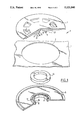
- FIG. 1 shows an exploded and partly broken away view of a valve according to the invention
- FIG. 2 is a bottom view of the inner plate shown in FIG. 1;
- FIG. 3 shows a section through the valve of FIG. 1 which is arranged in a body after filling with medium (FIG. 3a) and during filling with medium (FIG. 3b);
- FIGS. 4a and 4b show a section similar to FIG. 3a wherein the valve is located respectively in a convex and a concave portion of the body.
- FIG. 1 shows a body 1 for filling with medium 3 which is provided with an opening 2 that can be closed with a valve 4 according to the invention.
- the valve 4 comprises a flexible outer plate 5 that is arranged around the opening 2 such that a medium inlet 6 lies opposite opening 2.
- the outer plate 5 is adhered to the body 1 for example with adhesive or by means of welding.
- a flexible inner plate 7 Adhered on the inside to the body is a flexible inner plate 7.
- This latter plate is provided with a valve body 8 joined via laterally extending wings 9 to the inner plate 7 and forms an entity therewith.
- the wings are arranged diametrically and in rotational symmetry around a central valve body portion 10 which is provided on its side 11 facing the outer plate 5 with a guide member 12.
- Guide member 12 which can extend into the medium inlet 6 in the outer plate 5.
- the guide member 12 is further provided with a tool seating 13 so that, if required, the valve body 8 can be lifted and medium present in the body 1 can be drained off.
- a flat sealing ring 24 is clampingly attached round the guide member 12 and co-acts with an outer plate seating 14 and a valve body seating 15.
- the integrated inner plate 7-valve body 8 thus lies in a curved and tensioned position on the outer plate 5 when the valve 4 is closed, as shown in FIG. 3a.
- the outer plate seating 14 is provided with a rib 16 with a sharp edge 17 arranged coaxially around the medium inlet 6.
- the valve body seating 15 is provided with a coaxial rib 19 furnished with a sharp edge 18.
- the diameters of the ribs 16 and 19 differ.
- the diameter of the rib 19 is greater than that of rib 16.
- the diameter of rib 19 is, for example, 9 mm, of rib 16, 8 mm, and that of the flat sealing ring 24, 10 mm.
- the sealing ring 24 is substantially s-shaped in the radial direction and passage by medium in radial direction between the sealing ring 24 on the one side and the outer plate 5 or inner plate 7 on the other is substantially wholly prevented.
- positioning studs 21 are arranged on the wings 9, preferably on alternate wings 9 so that the wings 9 do not become too rigid.
- FIGS. 4a and 4b show clearly the multiple function of the wings if the valve according to the invention is situated in a curved portion of the body 1.
- the wings 9 press the valve body 8 onto the valve body seating 15.
- a number of the wings 9 act as pressure elements and a further number as pulling elements, depending on the position of these wings in the saddle-shaped portion.
- Suitable mediums which can be used include gases such as air, carbon dioxide, nitrogen, oxygen, and liquids such as liquid soap (shampoo), liquid chlorine, wine, lemonades and thin oils can be used as mediums.
- the body 1 can consist of a relatively medium-tight material such as polyethylene foil for use, for instance, in cardboard products.
Abstract
Description
Claims (16)
Applications Claiming Priority (2)
| Application Number | Priority Date | Filing Date | Title |
|---|---|---|---|
| NL8902430A NL8902430A (en) | 1989-09-29 | 1989-09-29 | INFLATABLE BODY WITH A VALVE, AND PACKAGING WITH SUCH A VALVE. |
| NL8902430 | 1989-09-29 |
Publications (1)
| Publication Number | Publication Date |
|---|---|
| US5121840A true US5121840A (en) | 1992-06-16 |
Family
ID=19855377
Family Applications (1)
| Application Number | Title | Priority Date | Filing Date |
|---|---|---|---|
| US07/588,197 Expired - Fee Related US5121840A (en) | 1989-09-29 | 1990-09-26 | Inflatable body with a valve |
Country Status (8)
| Country | Link |
|---|---|
| US (1) | US5121840A (en) |
| EP (1) | EP0420353B1 (en) |
| JP (1) | JPH03209078A (en) |
| AT (1) | ATE123124T1 (en) |
| DE (1) | DE69019653T2 (en) |
| DK (1) | DK0420353T3 (en) |
| ES (1) | ES2072377T3 (en) |
| NL (1) | NL8902430A (en) |
Cited By (25)
| Publication number | Priority date | Publication date | Assignee | Title |
|---|---|---|---|---|
| US5351710A (en) * | 1992-11-09 | 1994-10-04 | Reebok International Ltd. | Inflation mechanism for inflatable article of manufacture |
| WO1995022497A1 (en) * | 1994-02-22 | 1995-08-24 | Carson James A | Air removal device for sealed storage container |
| WO1998027371A1 (en) * | 1995-09-18 | 1998-06-25 | Chemberlen Christopher H | One direction ventilation valves |
| US5996800A (en) * | 1998-03-18 | 1999-12-07 | Pratt; David W. | Resealable plastic bag having venting means |
| US6253919B1 (en) | 1998-04-13 | 2001-07-03 | Sealed Air Corporation | Inflatable packing material |
| US6269968B1 (en) * | 1999-11-18 | 2001-08-07 | Niko Products, Inc. | Valve arrangement for an automatically sealing cup |
| US6314984B1 (en) * | 1999-08-05 | 2001-11-13 | Casa Artiach S.A. | Preferred valve stops with cushions |
| US6386247B1 (en) * | 2001-02-20 | 2002-05-14 | Helmut Richard Elze | Valve for a dunnage bag |
| US6439259B1 (en) * | 1999-06-22 | 2002-08-27 | Jeffrey L. Beaver | Air valve closure for containers |
| US6561236B1 (en) | 2000-03-08 | 2003-05-13 | Sealed Air Corporation (Us) | Inflatable packing and inflation apparatus |
| US20040007601A1 (en) * | 2002-06-26 | 2004-01-15 | Masatoshi Masuda | Valve mechanism for tube-type fluid container |
| US6785985B2 (en) | 2002-07-02 | 2004-09-07 | Reebok International Ltd. | Shoe having an inflatable bladder |
| US20040250864A1 (en) * | 2003-06-10 | 2004-12-16 | Zelson Larry Saul | Sanitary check valve |
| US20060272731A1 (en) * | 2005-06-02 | 2006-12-07 | Bridgestone Corporation | Container for sealant for pneumatic tires |
| US20080018100A1 (en) * | 2004-03-05 | 2008-01-24 | Mangar International Limited | Fluid Flow Connector |
| US20090026401A1 (en) * | 2007-07-27 | 2009-01-29 | Chris Dobkins | Systems and methods for vacuum sealing |
| US20090232423A1 (en) * | 2008-03-14 | 2009-09-17 | Azad Sabounjian | Valve for vacuum storage bag |
| US20090260418A1 (en) * | 2002-07-23 | 2009-10-22 | Apieron, Inc. | Disposable sensor for use in measuring an analyte in a gaseous sample |
| US20100059552A1 (en) * | 2008-09-10 | 2010-03-11 | Gpd Global, Inc. | Fluid dispensing valve with a spring plate |
| US20100242303A1 (en) * | 2009-03-26 | 2010-09-30 | Reebok International Ltd. | Valve for Regulating Pressure in a Fluid System |
| US8037623B2 (en) | 2001-06-21 | 2011-10-18 | Nike, Inc. | Article of footwear incorporating a fluid system |
| US8677652B2 (en) | 2002-07-02 | 2014-03-25 | Reebok International Ltd. | Shoe having an inflatable bladder |
| US11428345B2 (en) * | 2017-07-11 | 2022-08-30 | Microfab Service Gmbh | Micro check valve and system with multiple micro check valves and method for the production thereof |
| US11530754B2 (en) * | 2018-12-21 | 2022-12-20 | Aventics Gmbh | Sealing diaphragm and check valve having a sealing diaphragm for fluid technology applications |
| US11662034B2 (en) | 2019-07-24 | 2023-05-30 | Quest Medical, Inc. | Filtered vacuum relief vent valve |
Families Citing this family (4)
| Publication number | Priority date | Publication date | Assignee | Title |
|---|---|---|---|---|
| GB2244433B (en) * | 1990-05-10 | 1995-01-04 | Camberley Rubber Mouldings Lim | Valve assembly for breathing apparatus |
| DE4139668A1 (en) * | 1991-12-02 | 1993-06-03 | Kernforschungsz Karlsruhe | MICROVALVE AND METHOD FOR THE PRODUCTION THEREOF |
| AUPQ285599A0 (en) * | 1999-09-16 | 1999-10-07 | Mastavalve Pty Ltd | Filling stop valve |
| CN111609197B (en) * | 2020-04-27 | 2022-02-18 | 铜陵兴荣阀门管件有限公司 | Combined type exhaust valve |
Citations (16)
| Publication number | Priority date | Publication date | Assignee | Title |
|---|---|---|---|---|
| US886316A (en) * | 1906-09-13 | 1908-04-28 | Samuel T Langdon Jr | Valve for tires. |
| US1372878A (en) * | 1919-06-28 | 1921-03-29 | William F Leschen | Valve |
| US1423873A (en) * | 1920-02-05 | 1922-07-25 | Newsom Valve Company | Valve device for pneumatic tires |
| US1910961A (en) * | 1932-06-07 | 1933-05-23 | Agnes S Perry | Air valve |
| US2604297A (en) * | 1946-11-20 | 1952-07-22 | Thomas W Winstead | Valve for inflatable articles |
| DE861654C (en) * | 1950-02-21 | 1953-01-05 | Corbeletta & Cie Ets | Valve for air hoses, bubbles and other purposes |
| US2751953A (en) * | 1953-10-01 | 1956-06-26 | Bruce F Grimm | Collapsible container |
| US2942614A (en) * | 1958-11-03 | 1960-06-28 | Halkey Roberts Corp | Inflation valve |
| US2949927A (en) * | 1957-10-10 | 1960-08-23 | Henry H Mackal | Resilient inflation-deflation valve |
| US3085591A (en) * | 1960-08-22 | 1963-04-16 | Mine Safety Appliances Co | Exhalation valve |
| US3595467A (en) * | 1968-01-23 | 1971-07-27 | Luigi Goglio | Flexible sealed container provided with a one-way safety valve |
| US3913614A (en) * | 1973-10-09 | 1975-10-21 | Fike Metal Prod Corp | Pressure relief structure for aerosol containers |
| US3949934A (en) * | 1973-06-14 | 1976-04-13 | Luigi Goglio | Container having a valve movable between one-way flow and closed positions |
| DE3508777A1 (en) * | 1984-04-11 | 1985-11-14 | Dr.-Ing. Walter Frohn-Betriebe, 8000 München | Venting valve for storage and/or transport containers |
| FR2578943A1 (en) * | 1985-03-14 | 1986-09-19 | Commissariat Energie Atomique | Automatic non-return valve |
| EP0324519A2 (en) * | 1988-01-06 | 1989-07-19 | Klerk's Plastic Industrie B.V. | Inflatable body with a valve and a packaging with such a body |
-
1989
- 1989-09-29 NL NL8902430A patent/NL8902430A/en not_active Application Discontinuation
-
1990
- 1990-09-26 AT AT90202550T patent/ATE123124T1/en not_active IP Right Cessation
- 1990-09-26 ES ES90202550T patent/ES2072377T3/en not_active Expired - Lifetime
- 1990-09-26 DE DE69019653T patent/DE69019653T2/en not_active Expired - Fee Related
- 1990-09-26 US US07/588,197 patent/US5121840A/en not_active Expired - Fee Related
- 1990-09-26 DK DK90202550.1T patent/DK0420353T3/en active
- 1990-09-26 EP EP90202550A patent/EP0420353B1/en not_active Expired - Lifetime
- 1990-09-28 JP JP2262917A patent/JPH03209078A/en active Pending
Patent Citations (17)
| Publication number | Priority date | Publication date | Assignee | Title |
|---|---|---|---|---|
| US886316A (en) * | 1906-09-13 | 1908-04-28 | Samuel T Langdon Jr | Valve for tires. |
| US1372878A (en) * | 1919-06-28 | 1921-03-29 | William F Leschen | Valve |
| US1423873A (en) * | 1920-02-05 | 1922-07-25 | Newsom Valve Company | Valve device for pneumatic tires |
| US1910961A (en) * | 1932-06-07 | 1933-05-23 | Agnes S Perry | Air valve |
| US2604297A (en) * | 1946-11-20 | 1952-07-22 | Thomas W Winstead | Valve for inflatable articles |
| DE861654C (en) * | 1950-02-21 | 1953-01-05 | Corbeletta & Cie Ets | Valve for air hoses, bubbles and other purposes |
| US2751953A (en) * | 1953-10-01 | 1956-06-26 | Bruce F Grimm | Collapsible container |
| US2949927A (en) * | 1957-10-10 | 1960-08-23 | Henry H Mackal | Resilient inflation-deflation valve |
| US2942614A (en) * | 1958-11-03 | 1960-06-28 | Halkey Roberts Corp | Inflation valve |
| US3085591A (en) * | 1960-08-22 | 1963-04-16 | Mine Safety Appliances Co | Exhalation valve |
| US3595467A (en) * | 1968-01-23 | 1971-07-27 | Luigi Goglio | Flexible sealed container provided with a one-way safety valve |
| US3949934A (en) * | 1973-06-14 | 1976-04-13 | Luigi Goglio | Container having a valve movable between one-way flow and closed positions |
| US3913614A (en) * | 1973-10-09 | 1975-10-21 | Fike Metal Prod Corp | Pressure relief structure for aerosol containers |
| DE3508777A1 (en) * | 1984-04-11 | 1985-11-14 | Dr.-Ing. Walter Frohn-Betriebe, 8000 München | Venting valve for storage and/or transport containers |
| FR2578943A1 (en) * | 1985-03-14 | 1986-09-19 | Commissariat Energie Atomique | Automatic non-return valve |
| EP0324519A2 (en) * | 1988-01-06 | 1989-07-19 | Klerk's Plastic Industrie B.V. | Inflatable body with a valve and a packaging with such a body |
| US4966185A (en) * | 1988-01-06 | 1990-10-30 | Henk Schram | Inflatable body with a valve and a packaging with such a body |
Cited By (43)
| Publication number | Priority date | Publication date | Assignee | Title |
|---|---|---|---|---|
| US5351710A (en) * | 1992-11-09 | 1994-10-04 | Reebok International Ltd. | Inflation mechanism for inflatable article of manufacture |
| WO1995022497A1 (en) * | 1994-02-22 | 1995-08-24 | Carson James A | Air removal device for sealed storage container |
| US5450963A (en) * | 1994-02-22 | 1995-09-19 | Carson; James A. | Air removal device for sealed storage container |
| WO1998027371A1 (en) * | 1995-09-18 | 1998-06-25 | Chemberlen Christopher H | One direction ventilation valves |
| US5996800A (en) * | 1998-03-18 | 1999-12-07 | Pratt; David W. | Resealable plastic bag having venting means |
| US6253806B1 (en) | 1998-04-13 | 2001-07-03 | Sealed Air Corporation | Inflatable packing material and inflation system |
| US6729110B2 (en) | 1998-04-13 | 2004-05-04 | Sealed Air Corporation | System for inflating packing material |
| US6253919B1 (en) | 1998-04-13 | 2001-07-03 | Sealed Air Corporation | Inflatable packing material |
| US6439259B1 (en) * | 1999-06-22 | 2002-08-27 | Jeffrey L. Beaver | Air valve closure for containers |
| US6314984B1 (en) * | 1999-08-05 | 2001-11-13 | Casa Artiach S.A. | Preferred valve stops with cushions |
| US6786352B2 (en) | 1999-11-18 | 2004-09-07 | Domenic Belcastro | Valve arrangement for an automatically sealing cup |
| US6269968B1 (en) * | 1999-11-18 | 2001-08-07 | Niko Products, Inc. | Valve arrangement for an automatically sealing cup |
| US6561236B1 (en) | 2000-03-08 | 2003-05-13 | Sealed Air Corporation (Us) | Inflatable packing and inflation apparatus |
| US6386247B1 (en) * | 2001-02-20 | 2002-05-14 | Helmut Richard Elze | Valve for a dunnage bag |
| US8037623B2 (en) | 2001-06-21 | 2011-10-18 | Nike, Inc. | Article of footwear incorporating a fluid system |
| US20040007601A1 (en) * | 2002-06-26 | 2004-01-15 | Masatoshi Masuda | Valve mechanism for tube-type fluid container |
| US6968976B2 (en) * | 2002-06-26 | 2005-11-29 | Masatoshi Masuda | Valve mechanism for tube-type fluid container |
| US10251450B2 (en) | 2002-07-02 | 2019-04-09 | Reebok International Limited | Shoe having an inflatable bladder |
| US9474323B2 (en) | 2002-07-02 | 2016-10-25 | Reebok International Limited | Shoe having an inflatable bladder |
| US8677652B2 (en) | 2002-07-02 | 2014-03-25 | Reebok International Ltd. | Shoe having an inflatable bladder |
| US6785985B2 (en) | 2002-07-02 | 2004-09-07 | Reebok International Ltd. | Shoe having an inflatable bladder |
| US8151489B2 (en) | 2002-07-02 | 2012-04-10 | Reebok International Ltd. | Shoe having an inflatable bladder |
| US7735241B2 (en) | 2002-07-02 | 2010-06-15 | Reebok International, Ltd. | Shoe having an inflatable bladder |
| US7721465B2 (en) | 2002-07-02 | 2010-05-25 | Reebok International Ltd. | Shoe having an inflatable bladder |
| US20090260418A1 (en) * | 2002-07-23 | 2009-10-22 | Apieron, Inc. | Disposable sensor for use in measuring an analyte in a gaseous sample |
| US20080011373A1 (en) * | 2003-06-10 | 2008-01-17 | Zelson Larry S | Sanitary check valve |
| US7287545B2 (en) * | 2003-06-10 | 2007-10-30 | Larry Saul Zelson | Sanitary check valve |
| US20040250864A1 (en) * | 2003-06-10 | 2004-12-16 | Zelson Larry Saul | Sanitary check valve |
| US7484526B2 (en) | 2003-06-10 | 2009-02-03 | Larry Saul Zelson | Sanitary check valve |
| US20080018100A1 (en) * | 2004-03-05 | 2008-01-24 | Mangar International Limited | Fluid Flow Connector |
| US7841482B2 (en) * | 2004-03-05 | 2010-11-30 | Mangar International Limited | Fluid flow connector |
| US7878360B2 (en) * | 2005-06-02 | 2011-02-01 | Bridgestone Corporation | Container for sealant for pneumatic tires |
| US20060272731A1 (en) * | 2005-06-02 | 2006-12-07 | Bridgestone Corporation | Container for sealant for pneumatic tires |
| US8307864B2 (en) * | 2007-07-27 | 2012-11-13 | Chris Dobkins | Systems and methods for vacuum sealing |
| US20090026401A1 (en) * | 2007-07-27 | 2009-01-29 | Chris Dobkins | Systems and methods for vacuum sealing |
| US8066433B2 (en) | 2008-03-14 | 2011-11-29 | Pro-Mart Industries, Inc. | Valve for vacuum storage bag |
| US20090232423A1 (en) * | 2008-03-14 | 2009-09-17 | Azad Sabounjian | Valve for vacuum storage bag |
| US20100059552A1 (en) * | 2008-09-10 | 2010-03-11 | Gpd Global, Inc. | Fluid dispensing valve with a spring plate |
| US8250782B2 (en) | 2009-03-26 | 2012-08-28 | Reebok International Limited | Valve for regulating pressure in a fluid system |
| US20100242303A1 (en) * | 2009-03-26 | 2010-09-30 | Reebok International Ltd. | Valve for Regulating Pressure in a Fluid System |
| US11428345B2 (en) * | 2017-07-11 | 2022-08-30 | Microfab Service Gmbh | Micro check valve and system with multiple micro check valves and method for the production thereof |
| US11530754B2 (en) * | 2018-12-21 | 2022-12-20 | Aventics Gmbh | Sealing diaphragm and check valve having a sealing diaphragm for fluid technology applications |
| US11662034B2 (en) | 2019-07-24 | 2023-05-30 | Quest Medical, Inc. | Filtered vacuum relief vent valve |
Also Published As
| Publication number | Publication date |
|---|---|
| EP0420353A2 (en) | 1991-04-03 |
| EP0420353B1 (en) | 1995-05-24 |
| EP0420353A3 (en) | 1992-03-11 |
| DK0420353T3 (en) | 1995-07-24 |
| DE69019653T2 (en) | 1995-09-21 |
| DE69019653D1 (en) | 1995-06-29 |
| ATE123124T1 (en) | 1995-06-15 |
| NL8902430A (en) | 1991-04-16 |
| JPH03209078A (en) | 1991-09-12 |
| ES2072377T3 (en) | 1995-07-16 |
Similar Documents
| Publication | Publication Date | Title |
|---|---|---|
| US5121840A (en) | Inflatable body with a valve | |
| US3972452A (en) | Dispenser closure | |
| US5934514A (en) | Dispensing valve closure with inner seal | |
| US10080452B2 (en) | Cover device for a drink container | |
| CA2452204A1 (en) | Pressure-activated flexible valve | |
| US20110049169A1 (en) | Vented closure for container | |
| CA2540497A1 (en) | Flow control element for use with leak-proof cup assemblies | |
| US4181146A (en) | Two-way valve closing at balanced pressure condition | |
| JP2005530658A (en) | Container and sealing device | |
| WO1991008978A1 (en) | Flow control apparatus | |
| JPH11179238A (en) | Container cap for centrifuge | |
| US4586910A (en) | Inflation valve for balloons and the like | |
| EP1334917B1 (en) | Cap with one-way de-gas valve | |
| US4966185A (en) | Inflatable body with a valve and a packaging with such a body | |
| JPH11314657A (en) | Cap for container of centrifugal separator | |
| CA2189324A1 (en) | Container for pressurized fluids | |
| CN111683881A (en) | Air exhaust valve | |
| CN101337614A (en) | Spray valve | |
| US20040144435A1 (en) | Check valve | |
| EP0197459A2 (en) | Diaphragm valve | |
| CN213282642U (en) | Single-hand operated air bag seasoning bottle | |
| US2788924A (en) | Beaded-stem dispensing valve for gas-pressure containers | |
| WO1989010508A1 (en) | Inflatable containers and valves therefor | |
| GB2310190A (en) | Liquid foaming insert | |
| JPS6282020U (en) |
Legal Events
| Date | Code | Title | Description |
|---|---|---|---|
| CC | Certificate of correction | ||
| AS | Assignment |
Owner name: AMNION LICENSE B.V. J.J. ALLANSTRAAT 180,, NETHER Free format text: ASSIGNMENT OF ASSIGNORS INTEREST;ASSIGNOR:SCHRAM, HENK;REEL/FRAME:007170/0258 Effective date: 19940101 |
|
| AS | Assignment |
Owner name: KLERK'S PLASTIC INDUSTRIE B.V., NETHERLANDS Free format text: ASSIGNMENT OF ASSIGNORS INTEREST;ASSIGNOR:AMNION LICENCE B.V.;REEL/FRAME:007205/0624 Effective date: 19940205 |
|
| CC | Certificate of correction | ||
| CC | Certificate of correction | ||
| REMI | Maintenance fee reminder mailed | ||
| FPAY | Fee payment |
Year of fee payment: 4 |
|
| SULP | Surcharge for late payment | ||
| REMI | Maintenance fee reminder mailed | ||
| LAPS | Lapse for failure to pay maintenance fees | ||
| FP | Lapsed due to failure to pay maintenance fee |
Effective date: 20000616 |
|
| STCH | Information on status: patent discontinuation |
Free format text: PATENT EXPIRED DUE TO NONPAYMENT OF MAINTENANCE FEES UNDER 37 CFR 1.362 |