US5113956A - Forwardly folding tool bar - Google Patents
Forwardly folding tool bar Download PDFInfo
- Publication number
- US5113956A US5113956A US07/644,944 US64494491A US5113956A US 5113956 A US5113956 A US 5113956A US 64494491 A US64494491 A US 64494491A US 5113956 A US5113956 A US 5113956A
- Authority
- US
- United States
- Prior art keywords
- tool bar
- tongue
- bar section
- wing
- center
- Prior art date
- Legal status (The legal status is an assumption and is not a legal conclusion. Google has not performed a legal analysis and makes no representation as to the accuracy of the status listed.)
- Expired - Lifetime
Links
Images


Classifications
-
- A—HUMAN NECESSITIES
- A01—AGRICULTURE; FORESTRY; ANIMAL HUSBANDRY; HUNTING; TRAPPING; FISHING
- A01B—SOIL WORKING IN AGRICULTURE OR FORESTRY; PARTS, DETAILS, OR ACCESSORIES OF AGRICULTURAL MACHINES OR IMPLEMENTS, IN GENERAL
- A01B73/00—Means or arrangements to facilitate transportation of agricultural machines or implements, e.g. folding frames to reduce overall width
- A01B73/02—Folding frames
- A01B73/06—Folding frames foldable about a vertical axis
- A01B73/065—Folding frames foldable about a vertical axis to a position essentially forward of the axis, in relation to the direction of travel
Definitions
- This invention relates to a folding tool bar and more particularly to a forwardly folding tool bar.
- Tool bars are commonly used in farming operations.
- the conventional tool bars normally consist of a transversely extending tool bar or frame member having a hitch secured thereto which extends forwardly therefrom for attachment to a prime mover. Attachments such as cultivators, planter units, stalk cutters, etc. are mounted on the tool bar to perform various farming operations.
- a major problem associated with conventional tool bars is that the working or field width thereof must be substantially reduced to enable the implement to be transported from one location to another.
- Many types of tool bars employ a center tool bar section having wing tool bar sections extending outwardly therefrom.
- the wings are pivoted from a substantially horizontal working field position to an upright transport position. In most folding tool bars of this type, the upright position of the wings is not as stable as desired and may create undesirable stress on certain components of the tool bar.
- a further problem associated with the conventional folding tool bars is that they are not sufficiently flexible to compensate for irregular terrain such as in hill country, terraces, etc.
- Yet another disadvantage of the prior art devices is that the wheels which support the tool bar interfere with the mounting of various attachments on the tool bar due to the location of the wheels on the tool bar.
- Still another disadvantage of the conventional prior art tool bars is that they are difficult to move from the field position to the transport position and vice versa.
- Still another object of the invention is to provide a forwardly folding tool bar.
- Still another object of the invention is to provide a forwardly folding tool bar including an extendable hitch.
- Still another object of the invention is to provide a folding tool bar wherein the wheels which support the tool bar are mounted thereon in such a position so as not to interfere with the mounting of attachments thereon.
- Still another object of the invention is to provide a folding tool bar which has sufficient flexibility to enable the tool bar to be used in hilly country or on terraces.
- Still another object of the invention is to provide a forwardly folding tool bar which is quickly and easily moved from a working field position to a transport position and vice versa.
- Yet another object of the invention is to provide a forwardly folding tool bar which is economical of manufacture and durable in use.
- a forwardly folding tool bar which includes a center tool bar section which is disposed transversely to the direction of travel of the tool bar and which has opposite ends.
- Wing tool bar sections are pivotally secured, about vertical and horizontal axes, to the outer ends of the center tool bar section. In the field position, the wing tool bar sections are aligned in an end-to-end fashion with the center tool bar section.
- a plurality of wheels are mounted on the center tool bar section and the wing tool bar section and are positioned forwardly of the tool bar so that the wheels do not interfere with mounting of attachments to the tool bar section.
- An extendable or telescoping tongue is secured to the center tool bar section and extends forwardly therefrom for attachment to a prime mover.
- the telescoping tongue When the folding tool bar is in its working field condition, the telescoping tongue is in its retracted position. Hydraulic cylinders are operatively connected to the wing tool bar sections and are used to cause the wing tool bar sections to be pivotally moved forwardly relative to the center tool bar section when it is desired to move the tool bar to a transport position. As the wing tool bar sections are moved forwardly by the hydraulic cylinders, the telescoping tongue is extended and pushes the tractor forwardly so that the wing tool bar sections may be positioned rearwardly thereof. The wing tool bar sections are operatively secured to the telescoping tongue, when in the transport position, and the wheels supporting the wing tool bar sections are then raised out of ground engagement. Means is also provided for locking the telescoping tongue in its retracted position.
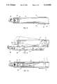
- FIG. 1 is a top elevational view of the tool bar of this invention in its field position
- FIG. 2 is a view similar to FIG. 1 except that the wings of the tool bar have been folded to a transport position;
- FIG. 3 is a perspective view illustrating the means by which the wings are moved with respect to the center tool bar section
- FIG. 4 is a side elevational view of the telescopic tongue of this invention.
- FIG. 5 is a partial sectional view of the tongue of this invention.
- FIG. 6 is a partial front elevational view of the tool bar
- FIG. 7 is a sectional view taken through the tongue
- FIG. 8 is a bottom view of the front portion of the tongue
- FIG. 9 is a side elevational view of the forward portion of the tongue.
- FIG. 10 is a sectional view seen on lines 10--10 of FIG. 9;
- FIG. 11 is a partial perspective view of the means for locking the telescoping tongue members in their withdrawn condition
- FIG. 12 is a side view of the locking mechanism of FIG. 11;
- FIG. 13 is a sectional view seen on lines 13--13 of FIG. 2;
- FIG. 14 is a view similar to that of FIG. 13 except that the gauge wheels on the wing sections have been lowered to disconnect the wing sections from the tongue;
- FIG. 15 is a side elevational view illustrating the relationship of one of the gauge wheels with respect to its supporting tool bar with the broken lines illustrating the position to which the gauge wheel may be moved;
- FIG. 16 is a view seen on lines 16--16 of FIG. 15.
- Tool bar 10 refers to the forwardly folding tool bar of this invention.
- Tool bar 10 includes a telescoping tongue 12 comprised of tubular tongue sections 14, 16, 18, 20 and 22.
- tongue sections 14 and 22 are comprised of steel and are eight inches by 10 inches.
- Tongue sections 16 and 18 are also preferably constructed of steel and are seven inches by nine inches.
- Tongue section 20 is also preferably constructed of steel and has a dimension of six inches by eight inches. It is preferred that all of the tongue sections have a wall thickness of 3/8 inch.
- Tongue section 16 is slidably mounted within tongue section 14 and tongue section 18 is slidably mounted in tongue sections 16 and 20. Tongue section 20 is slidably mounted in tongue section 22. Tongue lift assembly 26 is pivotally connected to tongue section 14 for raising and lowering the forward end of tongue section 14.
- Tongue lift assembly 26 includes an elongated frame member 28 which is pivotally connected to tongue section 14 by means of pin means 30 extending through plate P1, frame member 28 and plate P2.
- Hydraulic cylinder 32 is pivotally connected to and extends between 1 frame member 28 and tongue section 14.
- Stabilizer bracket 34 is secured to frame member 28 and is received in the underside of tongue section 14 to prevent lateral movement between frame member 28 and tongue section 14.
- Angle bracket 35 is secured to the upper forward end of stabilizer bracket and is adapted to be selectively positioned between pairs of openings "O" provided in tongue section 14, as will be described in more detail hereinafter.
- Hitch 36 is provided at the forward end of frame member 28 and is adapted to be secured to a prime mover such as a tractor or the like.
- Transversely extending transport beam 38 (FIG. 13) is secured to tongue section 14 adjacent the rearward end thereof and has a pair of hook receivers 40 and 42 provided at the opposite ends thereof.
- Rearwardly extending locking latch arms 44 and 46 are pivotally secured to the rearward end of tongue section 14 by bolts 48 and 50 (not shown) respectively and have locking lug portions 52 and 54 (not shown) provided at the rearward ends thereof.
- the rearward ends of latch arms 44 and 46 have an inverted U-shaped yoke 56 secured thereto and which extends over the upper end of tongue section 16 to interconnect the latch arms 44 and 46.
- Stops 58 and 60 are mounted on opposite sides of tongue section 14 and limit the downward pivotal movement of latch arms 44 and 46. Stops 58' and 60' (not shown) are mounted on opposite sides of the forward end of tongue section 22. When the locking latch arms 44 and 46 are in their lowered position and the tongue means is in its transport position, the engagement of lug portions 52 and 54 with the rearward ends of stops 58 and 60' prevents the separation of tongue section 16 from tongue section 14.
- Movable actuator arm 62 is positioned on one side of tongue section 14 and has its rearward end in close proximity with the lower forward end of latch arm 44 as seen in FIG. 12.
- actuator arm 62 The forward end of actuator arm 62 is in close proximity with the rearward end of plate P1 of tongue lift assembly 26 so that when tongue section 14 is raised by hydraulic cylinder 32, relative to frame member 28, plate P1 causes actuator arm 62 to move rearwardly.
- the rearward movement of actuator arm 62 causes latch arm 44, and latch arm 46, to pivot upwardly so that locking lug portions 52 and 54 are clear of stops 58 and 60, respectively, to permit the extension of the tongue sections relative to one another.
- Tool bar 10 includes a center tool bar section 66 having wing sections 68 and 70 pivotally connected thereto as seen in the drawings.
- Center tool bar section 66 includes a lower frame member 72 and an upper frame member 74 secured thereto and positioned thereabove.
- Wing section 70 includes an outer frame member 75 and an inner frame member 76.
- Frame member 74 is pivotally connected about a horizontal axis to inner frame member 76 by means of pivot pin 78.
- Frame member 75 is disposed in a horizontal plane below that of frame member 76 (FIG. 3) but is disposed in the same horizontal plane as lower frame member 72 of center section 66.
- Hydraulic cylinder 80 has its rod 82 pivotally connected to the outer end of frame member 76 at 84.
- the base end of cylinder 80 is pivotally connected at 86 to plates 88 and 90, which are secured to the outer end of upper frame member 74 and which extend outwardly and forwardly therefrom.
- Inner frame member 76 is pivotally connected to plate 88 and lower frame member 72 about a pivotal axis referred to generally by the reference numeral 92.
- outer frame member 75 to the inner frame member 76 at 78 permits frame member 75 to move upwardly and downwardly relative to frame member 76 so as to compensate for irregular terrain such as commonly found in terraces, hill country, etc.
- Wing section 68 is similarly constructed to wing section 70 and is similarly pivotally secured to center section 66 and therefore will not be described in detail.
- the outer ends of frame members 75 and 75' are provided with hooks 94 and 94' which are adapted to be received in the hook receiving portions 40 and 42 respective, as will be described in more detail hereinafter.
- Brace 95 is pivotally connected, about a vertical axis, at its rearward end to frame member 75 at 96 and is pivotally connected at its forward end, about a vertical axis, to one side of tongue section 14 at 97.
- brace 94' is pivotally connected to frame 75' and tongue section 14 at 97' and extends therebetween.
- a plurality of vertically movable gauge wheel assemblies 98 are mounted on frame members 72, 75 and 75' in a spaced apart relationship and in such a manner so that they are substantially positioned forwardly thereof so as not to interfere with the mounting of field attachments thereon such as planters, cultivators, etc.
- Each of the gauge wheel assemblies 98 comprises a clamp mounting bracket 100 which is secured to its respective tool bar frame member at the forward side thereon and at the underside thereof as best illustrated in FIG. 15.
- Clamp mounting bracket 100 is secured to the frame member by a pair of clamp bolts 102 and 104.
- a pair of horizontally spaced apart plates or arms 106 and 108 are pivoted to the sides 110 and 112 respectively of clamp mounting bracket 100 by pins 114 and normally extend downwardly and forwardly therefrom as seen in FIG. 15.
- Wheel 114 is rotatably mounted between the lower ends of plates 106 and 108 by axle assembly 116.
- Hydraulic cylinder 118 is positioned between sides 110 and 112 and has its body 120 pivotally secured thereto by pin means 122.
- the lower end of rod 124 of cylinder 118 is pivotally secured to plates 106 and 108 at 126 to enable the wheel 114 to be pivoted between the position illustrated by solid lines in FIG. 15 to the position illustrated by broken lines in FIG. 15.
- the normal method of operating the tool bar of this invention is as follows. Assuming that the tool bar of this invention is in the field position of FIG. 1, the wing sections 68 and 70 are permitted to flex about horizontal pivot axis defined by pins 78 and 78' so that the tool bar may compensate for irregular terrain such as experienced in hill country, terraces, etc.
- the forward mounting of the gauge wheel assemblies 96 on the tool bar sections 72, 75 and 75' insure that the various planter units, etc. may be mounted on the tool bar section without interference from the wheel.
- the tool bar of this invention may be used for drills or cultivating, or any implement that will clamp to a standard 7 inch by 7 inch bar.
- Hydraulic cylinder 32 has been extended to cause the forward end of tongue section 14 to be pivoted with respect to frame member 28 as previously described. Such pivoting causes the lower end of plate P1 to move rearwardly which causes actuator rod 62 to be moved rearwardly which in turn causes the latch arms 44 and 46 to be pivotally moved upwardly so that the tongue sections may be extended relative to one another. Hydraulic cylinders 80 and 80' are then retracted so that wing sections 68 and 70 are pivotally moved from the field position of FIG. 1 to the transport position of FIG. 2.
- braces 95 and 95' exert force on tongue section 14 to causes the extension of the various tongue sections with the extension of the tongue sections causing the tractor to roll forwardly.
- Cylinders 80 and 80' are extended until frame members 75 and 75' are substantially parallel to the tongue of the apparatus and so that the hooks 94 and 94' are positioned over the hook receiving portions 42 and 40 as illustrated in FIG. 14.
- the hydraulic cylinders for the gauge wheel assemblies on the wing sections 68 and 70 are then retracted which causes wing sections 68 and 70 to be lowered until the hooks 94 and 94' are received in the hook receiving portions 42 and 40.
- the tool bar When the tool bar is in the transport position of FIG. 2, the tool bar may be easily moved from one location to another.
- the gauge wheel assemblies on the wing sections 68 and 70 are lowered into ground engagement as illustrated in FIG. 14 so that the hooks 94 and 94' disengage from the hook receiving portions 42 and 40.
- Hydraulic cylinders 80 and 80' are then extended which causes the wing sections 68 and 70 to pivotally move from the position of FIG. 2 to the position of FIG. 1 with the braces 95 and 95, causing the tongue sections to telescope within one another.
- the tongue lift assembly cylinder 32 is retracted to permit the actuator rod 62 to move forwardly thereby permitting the latch arms 44 and 46 to move downwardly so that the lug portions 52 and 54 are positioned as illustrated in FIG. 12 to positively maintain the tongue sections in the retracted position.
Abstract
Description
Claims (7)
Priority Applications (2)
| Application Number | Priority Date | Filing Date | Title |
|---|---|---|---|
| US07/644,944 US5113956A (en) | 1991-01-23 | 1991-01-23 | Forwardly folding tool bar |
| CA002059925A CA2059925C (en) | 1991-01-23 | 1992-01-23 | Forwardly folding tool bar |
Applications Claiming Priority (1)
| Application Number | Priority Date | Filing Date | Title |
|---|---|---|---|
| US07/644,944 US5113956A (en) | 1991-01-23 | 1991-01-23 | Forwardly folding tool bar |
Publications (1)
| Publication Number | Publication Date |
|---|---|
| US5113956A true US5113956A (en) | 1992-05-19 |
Family
ID=24587008
Family Applications (1)
| Application Number | Title | Priority Date | Filing Date |
|---|---|---|---|
| US07/644,944 Expired - Lifetime US5113956A (en) | 1991-01-23 | 1991-01-23 | Forwardly folding tool bar |
Country Status (2)
| Country | Link |
|---|---|
| US (1) | US5113956A (en) |
| CA (1) | CA2059925C (en) |
Cited By (69)
| Publication number | Priority date | Publication date | Assignee | Title |
|---|---|---|---|---|
| US5154240A (en) * | 1991-08-15 | 1992-10-13 | Calkins Manufacturing Company | Folding implement frame |
| US5291954A (en) * | 1992-08-21 | 1994-03-08 | Kirwan Gerald R | Front mounted, front folding tool carrier bar |
| US5488996A (en) * | 1994-07-01 | 1996-02-06 | Kinze Manufacturing, Inc. | Forward-folding, winged, implement frame |
| US5535688A (en) * | 1994-12-22 | 1996-07-16 | Kaufman; Michael J. | Tool bar planter system for combines |
| US5647440A (en) * | 1994-07-01 | 1997-07-15 | Kinze Manufacturing, Inc. | Forward-folding, winged, implement frame |
| EP0812531A1 (en) * | 1996-06-12 | 1997-12-17 | Fella-Werke GmbH | Farm implement with foldable large working width |
| US5715893A (en) * | 1995-02-13 | 1998-02-10 | Houck; Shane A. | Implement convertible between a use position and a transport position |
| US5829370A (en) * | 1996-07-08 | 1998-11-03 | Bender; Harold C. | Rearward folding multi-row crop planter |
| US5839516A (en) * | 1996-03-12 | 1998-11-24 | Unverferth Manufacturing Co., Inc. | Folding frame assembly for a rolling harrow implement having a transport position in which the main frame is upwardly pivoted and the wing frames are forwardly pivoted |
| US5887663A (en) * | 1997-02-14 | 1999-03-30 | Case Corporation | Marker-actuated implement control circuit for an agricultural machine |
| US6076613A (en) * | 1998-09-08 | 2000-06-20 | Orthman Manufacturing, Inc. | Forwardly-folding agricultural implement |
| US6206105B1 (en) | 1999-05-13 | 2001-03-27 | Milford E. Friesen | Forwardly folding tool bar |
| US6293352B1 (en) * | 1998-11-12 | 2001-09-25 | Flexi-Coil Ltd. | Telescoping hitch for planting implement |
| US6321852B1 (en) * | 2000-01-26 | 2001-11-27 | Deere & Company | Agricultural implement frame having a transport configuration and a working configuration |
| FR2813753A1 (en) * | 2000-09-08 | 2002-03-15 | Exel Ind | Spray bar for plant protection agents is made up of two swivelling sections locked together in spread position by levers, whose length can be adjusted, mounted on one section which fit over pins on other section |
| EP1205098A1 (en) * | 2000-11-07 | 2002-05-15 | Deere & Company | Agricultural machine frame |
| US6408950B1 (en) * | 2000-04-20 | 2002-06-25 | Kenneth E. Shoup | Foldable implement frame and hitch |
| US6550543B1 (en) * | 1997-03-12 | 2003-04-22 | Flexi-Coil Ltd. | Forward folding tillage implement |
| US6609574B1 (en) | 2000-08-10 | 2003-08-26 | Jeffrey Lee Collins | Folding support frame |
| US6663134B2 (en) | 2002-01-31 | 2003-12-16 | Case, Llc | Planter hitch apparatus |
| US6666155B2 (en) | 2002-03-04 | 2003-12-23 | Case, Llc | Planter with centrally mounted coulter apparatus |
| US6681866B1 (en) | 2002-03-04 | 2004-01-27 | Case, Llc | Planter hitch apparatus |
| US6691794B2 (en) * | 2002-01-31 | 2004-02-17 | Case, Llc | Planter hitch locking and alignment apparatus |
| US6702035B1 (en) * | 2003-04-01 | 2004-03-09 | Milford E. Friesen | Forwardly folding tool bar |
| US20040050563A1 (en) * | 2000-04-20 | 2004-03-18 | Shoup Kenneth E. | Foldable implement frame and hitch |
| US20040065059A1 (en) * | 2002-10-03 | 2004-04-08 | Cullen Steven R. | Bagging machine having a collapsible tunnel |
| US20040107683A1 (en) * | 2002-12-10 | 2004-06-10 | Kelderman Gary L. | Expanding and contracting implements |
| EP1493325A1 (en) * | 2003-07-04 | 2005-01-05 | Maschinenfabrik Bernard Krone GmbH | Haymaking machine |
| EP1493322A1 (en) * | 2003-07-04 | 2005-01-05 | Maschinenfabrik Bernard Krone GmbH | Haymaking machine |
| US20050087350A1 (en) * | 2003-10-28 | 2005-04-28 | Bauer Vaughn L. | Sectional toolbar for a planter |
| US20050155332A1 (en) * | 2002-10-03 | 2005-07-21 | Cullen Steven R. | Bagging machine with a tunnel at least partially formed of flexible material |
| US20050166555A1 (en) * | 2002-10-03 | 2005-08-04 | Cullen Steven R. | Bagging machine with an adjustable tunnel |
| US20060073000A1 (en) * | 2004-08-04 | 2006-04-06 | Ronald Terfry | Fairway dragger |
| US20060090910A1 (en) * | 2004-07-20 | 2006-05-04 | Shane Houck | Implement convertible between use configuration and transport configuration |
| US20070163791A1 (en) * | 2006-01-17 | 2007-07-19 | Agco Corporation | Front folding agricultural implement frame with rearwardly telescoping tongue |
| WO2007093034A1 (en) * | 2006-02-15 | 2007-08-23 | Straw Track Manufacturing Inc. | Biased diagonal implement brace |
| US20090056296A1 (en) * | 2007-08-28 | 2009-03-05 | Patterson Roger L | Header transport |
| US7562719B1 (en) * | 2006-03-10 | 2009-07-21 | Misenhelder John G | Tool bar with forward folding wings |
| US7594374B2 (en) | 2002-10-03 | 2009-09-29 | S.R.C. Innovations, Llc | Bagging machines having a collapsible tunnel |
| US7604068B1 (en) | 2005-02-24 | 2009-10-20 | Arlyn E. Friesen | Forwardly folding tool bar |
| US20100101811A1 (en) * | 2008-10-24 | 2010-04-29 | Friggstad Terrance A | Agricultural implement having folding draft links |
| US20100101813A1 (en) * | 2008-10-24 | 2010-04-29 | Friggstad Terrance A | Agricultural implement having forward folding wing booms |
| US20100126744A1 (en) * | 2008-11-21 | 2010-05-27 | Cnh America Llc | Implement frame with front folding wings and transport wheels |
| US20100126743A1 (en) * | 2008-11-21 | 2010-05-27 | Cnh America Llc | Implement frame with front folding wings and transport wheels |
| US20100126742A1 (en) * | 2008-11-21 | 2010-05-27 | Cnh America Llc | Implement frame with front folding wings and transport wheels |
| EP2371194A1 (en) * | 2010-03-30 | 2011-10-05 | Kverneland ASA | Device for spreading seeds and/or fertilisers |
| US20120256396A1 (en) * | 2009-12-16 | 2012-10-11 | Lely Patent N.V. | Agricultural device |
| US20130000268A1 (en) * | 2010-03-08 | 2013-01-03 | Forage Innovations B.V. | Device for displacing mown crop |
| US20130008360A1 (en) * | 2011-07-05 | 2013-01-10 | Kongskilde Industries Inc. | Automatic guidance system for pull-type agricultural implement |
| US20130233580A1 (en) * | 2012-03-08 | 2013-09-12 | Kinze Manufacturing, Inc. | Smooth forward folding implement frame |
| US20130264082A1 (en) * | 2012-04-06 | 2013-10-10 | Dennis R. Solbrack | Jointed folding arm |
| US20140096983A1 (en) * | 2012-07-03 | 2014-04-10 | Kinze Manufacturing, Inc. | Forward rotating transport axle |
| US20150042068A1 (en) * | 2013-08-08 | 2015-02-12 | Mammoet USA South Inc. | Transport Trailer with Adjustable-Width Swing Arms |
| US20150319912A1 (en) * | 2014-05-08 | 2015-11-12 | Kinze Manufacturing, Inc. | Front fold implement frame with pivotal draft link connection |
| US20150327429A1 (en) * | 2012-12-17 | 2015-11-19 | Precision Planting Llc | Agricultural toolbar line routing systems and methods |
| US20160007534A1 (en) * | 2014-07-09 | 2016-01-14 | Cnh Industrial America Llc | Header retaining system for a lateral transport center pivot agricultural machine |
| EP1488685B2 (en) † | 2003-06-20 | 2016-04-27 | Maschinenfabrik Bernard Krone GmbH | Haymaking machine |
| US9526204B2 (en) | 2013-09-11 | 2016-12-27 | Cnh Industrial America Llc | Lateral transport wheel assembly |
| US20170006762A1 (en) * | 2015-07-10 | 2017-01-12 | Cnh Industrial America Llc | Caster wheel assembly for an agricultural implement |
| US9565800B2 (en) | 2014-09-08 | 2017-02-14 | Cnh Industrial America Llc | Windrow shield control system for a header of an agricultural harvester |
| US9596808B2 (en) | 2014-04-30 | 2017-03-21 | Cnh Industrial America Llc | Transport system for a center pivot agricultural machine |
| US9832921B2 (en) | 2015-07-10 | 2017-12-05 | Cnh Industrial America Llc | Toolbar wing support system for an agricultural implement |
| DE102017115928A1 (en) * | 2017-07-14 | 2019-01-17 | Horsch Maschinen Gmbh | Trailed agricultural implement and method for lifting machine parts |
| US10426075B2 (en) * | 2017-07-24 | 2019-10-01 | Cnh Industrial America Llc | Mounted front fold agricultural toolbar |
| US10506757B2 (en) | 2017-03-28 | 2019-12-17 | Cnh Industrial Canada, Ltd. | Folding implement with tractor assist |
| US10798865B2 (en) | 2016-01-19 | 2020-10-13 | Fast Global Solutions Inc. | Agricultural implement with lift assist and uplift capability |
| US20210392807A1 (en) * | 2020-06-18 | 2021-12-23 | Ag Premier, Inc. | Agricultural tool bar system |
| US11343953B2 (en) | 2019-06-24 | 2022-05-31 | Cnh Industrial America Llc | Counter spring latch mechanism and agricultural machine |
| US11778937B2 (en) * | 2018-04-17 | 2023-10-10 | Dennis Anderson | Modular agricultural toolbar |
Citations (16)
| Publication number | Priority date | Publication date | Assignee | Title |
|---|---|---|---|---|
| US3635495A (en) * | 1969-11-28 | 1972-01-18 | Int Harvester Co | Telescoping implement tongue |
| US3791673A (en) * | 1972-11-08 | 1974-02-12 | American Prod Inc | Folding means for implement frame structures |
| US4137852A (en) * | 1976-09-03 | 1979-02-06 | Deere & Company | Forwardly foldable toolbar |
| US4171022A (en) * | 1977-09-26 | 1979-10-16 | Great Plains Manufacturing Incorporated | Foldable construction for agricultural implements |
| US4319643A (en) * | 1980-03-03 | 1982-03-16 | Carmaco, Inc. | Front folding agricultural tool bar with movable carriage to which wings coupled |
| US4504076A (en) * | 1983-09-16 | 1985-03-12 | Deere & Company | Forward-folding agricultural implement featuring narrow row spacing |
| EP0155689A2 (en) * | 1984-03-23 | 1985-09-25 | Deere & Company | Soil-working implement |
| US4582143A (en) * | 1983-12-27 | 1986-04-15 | Deere & Company | Forwardly-folding agricultural implement |
| US4596290A (en) * | 1982-12-27 | 1986-06-24 | Deere & Co | Agricultural machine with offset forwardly folding frame |
| FR2586623A1 (en) * | 1985-09-05 | 1987-03-06 | Guillemaud Dominique | Vehicle towing bar |
| US4664202A (en) * | 1984-09-07 | 1987-05-12 | Great Plains Manufacturing, Inc. | Folding implement frame for grain drills and the like |
| US4721168A (en) * | 1985-09-23 | 1988-01-26 | Kinzenbaw Jon E | Agricultural implement with raisable lift frame rotatable about vertical axis |
| US4721167A (en) * | 1984-03-23 | 1988-01-26 | Deere & Company | Hitch flexing hinge |
| US4723787A (en) * | 1986-02-28 | 1988-02-09 | Deere & Company | Implement transport hitch |
| US4945997A (en) * | 1989-08-16 | 1990-08-07 | Adee Raymond A | Folding agricultural implement |
| US4974684A (en) * | 1990-02-26 | 1990-12-04 | Deere & Company | Walking beam retainer |
-
1991
- 1991-01-23 US US07/644,944 patent/US5113956A/en not_active Expired - Lifetime
-
1992
- 1992-01-23 CA CA002059925A patent/CA2059925C/en not_active Expired - Lifetime
Patent Citations (16)
| Publication number | Priority date | Publication date | Assignee | Title |
|---|---|---|---|---|
| US3635495A (en) * | 1969-11-28 | 1972-01-18 | Int Harvester Co | Telescoping implement tongue |
| US3791673A (en) * | 1972-11-08 | 1974-02-12 | American Prod Inc | Folding means for implement frame structures |
| US4137852A (en) * | 1976-09-03 | 1979-02-06 | Deere & Company | Forwardly foldable toolbar |
| US4171022A (en) * | 1977-09-26 | 1979-10-16 | Great Plains Manufacturing Incorporated | Foldable construction for agricultural implements |
| US4319643A (en) * | 1980-03-03 | 1982-03-16 | Carmaco, Inc. | Front folding agricultural tool bar with movable carriage to which wings coupled |
| US4596290A (en) * | 1982-12-27 | 1986-06-24 | Deere & Co | Agricultural machine with offset forwardly folding frame |
| US4504076A (en) * | 1983-09-16 | 1985-03-12 | Deere & Company | Forward-folding agricultural implement featuring narrow row spacing |
| US4582143A (en) * | 1983-12-27 | 1986-04-15 | Deere & Company | Forwardly-folding agricultural implement |
| EP0155689A2 (en) * | 1984-03-23 | 1985-09-25 | Deere & Company | Soil-working implement |
| US4721167A (en) * | 1984-03-23 | 1988-01-26 | Deere & Company | Hitch flexing hinge |
| US4664202A (en) * | 1984-09-07 | 1987-05-12 | Great Plains Manufacturing, Inc. | Folding implement frame for grain drills and the like |
| FR2586623A1 (en) * | 1985-09-05 | 1987-03-06 | Guillemaud Dominique | Vehicle towing bar |
| US4721168A (en) * | 1985-09-23 | 1988-01-26 | Kinzenbaw Jon E | Agricultural implement with raisable lift frame rotatable about vertical axis |
| US4723787A (en) * | 1986-02-28 | 1988-02-09 | Deere & Company | Implement transport hitch |
| US4945997A (en) * | 1989-08-16 | 1990-08-07 | Adee Raymond A | Folding agricultural implement |
| US4974684A (en) * | 1990-02-26 | 1990-12-04 | Deere & Company | Walking beam retainer |
Non-Patent Citations (23)
| Title |
|---|
| Agri Products Mulcher, p. 50. * |
| Agri-Products Mulcher, p. 50. |
| Brillion Iron Works, p. 42, Brillion Pulverizers. * |
| Great Pains Advertisment, "Solid Stand Folding Drills," p. 12 (no date). |
| Great Pains Advertisment, Solid Stand Folding Drills, p. 12 (no date). * |
| Great Plains Advertisement, "Folding No-Til Drills," p. 15 (no date). |
| Great Plains Advertisement, "Multi-Flex Planter", p. 18 (no date). |
| Great Plains Advertisement, Folding No Til Drills, p. 15 (no date). * |
| Great Plains Advertisement, Multi Flex Planter , p. 18 (no date). * |
| Great Plains Brochure, "Solid Stand 3-Section Folding Drill," 1986, pp. 1-4. |
| Great Plains Brochure, Solid Stand 3 Section Folding Drill, 1986, pp. 1 4. * |
| Great Plains, p. 12. * |
| Great Plains, p. 15. * |
| Great Plains, p. 18. * |
| Kinze Brochure, "Multi-row Mobility", Rear Folding Planter Bar, 1983, pp. 1-4. |
| Kinze Brochure, Multi row Mobility , Rear Folding Planter Bar, 1983, pp. 1 4. * |
| Shoup Manufacturing Company brochure, "Front Folding Planter Frams," (no date) pp. 1-4. |
| Shoup Manufacturing Company brochure, Front Folding Planter Frams, (no date) pp. 1 4. * |
| Shoup Manufacturing Company, Shoup Front Folding Planter. * |
| Tillage and Earthmoving Equipment Catalog, Jan. 1991, "Orthman 12-50 16-Row RTC" Advertisement, p. 50. |
| Tillage and Earthmoving Equipment Catalog, Jan. 1991, Brillion "WL Pulvi-Mulcher" advertisement , pp. 41-42. |
| Tillage and Earthmoving Equipment Catalog, Jan. 1991, Brillion WL Pulvi Mulcher advertisement , pp. 41 42. * |
| Tillage and Earthmoving Equipment Catalog, Jan. 1991, Orthman 12 50 16 Row RTC Advertisement, p. 50. * |
Cited By (96)
| Publication number | Priority date | Publication date | Assignee | Title |
|---|---|---|---|---|
| US5154240A (en) * | 1991-08-15 | 1992-10-13 | Calkins Manufacturing Company | Folding implement frame |
| US5291954A (en) * | 1992-08-21 | 1994-03-08 | Kirwan Gerald R | Front mounted, front folding tool carrier bar |
| US5488996A (en) * | 1994-07-01 | 1996-02-06 | Kinze Manufacturing, Inc. | Forward-folding, winged, implement frame |
| US5647440A (en) * | 1994-07-01 | 1997-07-15 | Kinze Manufacturing, Inc. | Forward-folding, winged, implement frame |
| US5535688A (en) * | 1994-12-22 | 1996-07-16 | Kaufman; Michael J. | Tool bar planter system for combines |
| US5715893A (en) * | 1995-02-13 | 1998-02-10 | Houck; Shane A. | Implement convertible between a use position and a transport position |
| US5839516A (en) * | 1996-03-12 | 1998-11-24 | Unverferth Manufacturing Co., Inc. | Folding frame assembly for a rolling harrow implement having a transport position in which the main frame is upwardly pivoted and the wing frames are forwardly pivoted |
| EP0812531A1 (en) * | 1996-06-12 | 1997-12-17 | Fella-Werke GmbH | Farm implement with foldable large working width |
| US5829370A (en) * | 1996-07-08 | 1998-11-03 | Bender; Harold C. | Rearward folding multi-row crop planter |
| US5887663A (en) * | 1997-02-14 | 1999-03-30 | Case Corporation | Marker-actuated implement control circuit for an agricultural machine |
| US6550543B1 (en) * | 1997-03-12 | 2003-04-22 | Flexi-Coil Ltd. | Forward folding tillage implement |
| US6076613A (en) * | 1998-09-08 | 2000-06-20 | Orthman Manufacturing, Inc. | Forwardly-folding agricultural implement |
| US6293352B1 (en) * | 1998-11-12 | 2001-09-25 | Flexi-Coil Ltd. | Telescoping hitch for planting implement |
| US6206105B1 (en) | 1999-05-13 | 2001-03-27 | Milford E. Friesen | Forwardly folding tool bar |
| US6321852B1 (en) * | 2000-01-26 | 2001-11-27 | Deere & Company | Agricultural implement frame having a transport configuration and a working configuration |
| US6408950B1 (en) * | 2000-04-20 | 2002-06-25 | Kenneth E. Shoup | Foldable implement frame and hitch |
| US6902010B2 (en) * | 2000-04-20 | 2005-06-07 | Kenneth E. Shoup | Foldable implement frame and hitch |
| US20040050563A1 (en) * | 2000-04-20 | 2004-03-18 | Shoup Kenneth E. | Foldable implement frame and hitch |
| US6609574B1 (en) | 2000-08-10 | 2003-08-26 | Jeffrey Lee Collins | Folding support frame |
| FR2813753A1 (en) * | 2000-09-08 | 2002-03-15 | Exel Ind | Spray bar for plant protection agents is made up of two swivelling sections locked together in spread position by levers, whose length can be adjusted, mounted on one section which fit over pins on other section |
| EP1205098A1 (en) * | 2000-11-07 | 2002-05-15 | Deere & Company | Agricultural machine frame |
| US6663134B2 (en) | 2002-01-31 | 2003-12-16 | Case, Llc | Planter hitch apparatus |
| US6691794B2 (en) * | 2002-01-31 | 2004-02-17 | Case, Llc | Planter hitch locking and alignment apparatus |
| US6681866B1 (en) | 2002-03-04 | 2004-01-27 | Case, Llc | Planter hitch apparatus |
| US6666155B2 (en) | 2002-03-04 | 2003-12-23 | Case, Llc | Planter with centrally mounted coulter apparatus |
| US6915863B2 (en) | 2002-03-04 | 2005-07-12 | Cnh America Llc | Planter bar support wheel assembly |
| US20040149190A1 (en) * | 2002-03-04 | 2004-08-05 | Raducha Kregg J. | Planter bar support wheel assembly |
| US20040065059A1 (en) * | 2002-10-03 | 2004-04-08 | Cullen Steven R. | Bagging machine having a collapsible tunnel |
| US7437861B2 (en) | 2002-10-03 | 2008-10-21 | Src Innovations, Llc | Bagging machine with a tunnel at least partially formed of flexible material |
| US6907714B2 (en) * | 2002-10-03 | 2005-06-21 | Src Innovations, Llc | Bagging machine having a collapsible tunnel |
| US20050155332A1 (en) * | 2002-10-03 | 2005-07-21 | Cullen Steven R. | Bagging machine with a tunnel at least partially formed of flexible material |
| US20050166555A1 (en) * | 2002-10-03 | 2005-08-04 | Cullen Steven R. | Bagging machine with an adjustable tunnel |
| US7594374B2 (en) | 2002-10-03 | 2009-09-29 | S.R.C. Innovations, Llc | Bagging machines having a collapsible tunnel |
| US20040107683A1 (en) * | 2002-12-10 | 2004-06-10 | Kelderman Gary L. | Expanding and contracting implements |
| US6901728B2 (en) * | 2002-12-10 | 2005-06-07 | Gary L. Kelderman | Expanding and contracting implements |
| US6702035B1 (en) * | 2003-04-01 | 2004-03-09 | Milford E. Friesen | Forwardly folding tool bar |
| EP1488685B2 (en) † | 2003-06-20 | 2016-04-27 | Maschinenfabrik Bernard Krone GmbH | Haymaking machine |
| EP1493322A1 (en) * | 2003-07-04 | 2005-01-05 | Maschinenfabrik Bernard Krone GmbH | Haymaking machine |
| EP1493325A1 (en) * | 2003-07-04 | 2005-01-05 | Maschinenfabrik Bernard Krone GmbH | Haymaking machine |
| US20050087350A1 (en) * | 2003-10-28 | 2005-04-28 | Bauer Vaughn L. | Sectional toolbar for a planter |
| US20060090910A1 (en) * | 2004-07-20 | 2006-05-04 | Shane Houck | Implement convertible between use configuration and transport configuration |
| US20060073000A1 (en) * | 2004-08-04 | 2006-04-06 | Ronald Terfry | Fairway dragger |
| US7604068B1 (en) | 2005-02-24 | 2009-10-20 | Arlyn E. Friesen | Forwardly folding tool bar |
| US20070163791A1 (en) * | 2006-01-17 | 2007-07-19 | Agco Corporation | Front folding agricultural implement frame with rearwardly telescoping tongue |
| US8127861B2 (en) | 2006-01-17 | 2012-03-06 | Agco Corporation | Front folding agricultural implement frame with rearwardly telescoping tongue |
| WO2007093034A1 (en) * | 2006-02-15 | 2007-08-23 | Straw Track Manufacturing Inc. | Biased diagonal implement brace |
| AU2007215326B2 (en) * | 2006-02-15 | 2011-05-26 | Seedmaster Manufacturing Ltd. | Biased diagonal implement brace |
| US7562719B1 (en) * | 2006-03-10 | 2009-07-21 | Misenhelder John G | Tool bar with forward folding wings |
| US7712544B1 (en) * | 2006-03-10 | 2010-05-11 | Misenhelder John G | Tool bar with forward folding wings |
| US20090056296A1 (en) * | 2007-08-28 | 2009-03-05 | Patterson Roger L | Header transport |
| US8117812B2 (en) * | 2007-08-28 | 2012-02-21 | Macdon Industries Ltd. | Header transport |
| US20100101813A1 (en) * | 2008-10-24 | 2010-04-29 | Friggstad Terrance A | Agricultural implement having forward folding wing booms |
| US20100101811A1 (en) * | 2008-10-24 | 2010-04-29 | Friggstad Terrance A | Agricultural implement having folding draft links |
| US7854273B2 (en) * | 2008-10-24 | 2010-12-21 | Cnh Canada, Ltd. | Agricultural implement having folding draft links |
| US7854272B2 (en) * | 2008-10-24 | 2010-12-21 | Cnh Canada, Ltd. | Agricultural implement having forward folding wing booms |
| US20100126744A1 (en) * | 2008-11-21 | 2010-05-27 | Cnh America Llc | Implement frame with front folding wings and transport wheels |
| US20100126743A1 (en) * | 2008-11-21 | 2010-05-27 | Cnh America Llc | Implement frame with front folding wings and transport wheels |
| US8141652B2 (en) | 2008-11-21 | 2012-03-27 | Cnh America Llc | Implement frame with front folding wings and transport wheels |
| US20100126742A1 (en) * | 2008-11-21 | 2010-05-27 | Cnh America Llc | Implement frame with front folding wings and transport wheels |
| US7921932B2 (en) | 2008-11-21 | 2011-04-12 | Cnh America Llc | Implement frame with front folding wings and transport wheels |
| US8567518B2 (en) * | 2009-12-16 | 2013-10-29 | Lely Patent N.V. | Agricultural device movable between a transport position and a working position |
| US20120256396A1 (en) * | 2009-12-16 | 2012-10-11 | Lely Patent N.V. | Agricultural device |
| US8820041B2 (en) | 2010-03-08 | 2014-09-02 | Forage Innovations B.V. | Haymaking device movable between transport and operative positions and method therefor |
| US20130000268A1 (en) * | 2010-03-08 | 2013-01-03 | Forage Innovations B.V. | Device for displacing mown crop |
| US8602121B2 (en) * | 2010-03-08 | 2013-12-10 | Forage Innovations B.V. | Haymaking device movable between transport and operative positions |
| EP2371194A1 (en) * | 2010-03-30 | 2011-10-05 | Kverneland ASA | Device for spreading seeds and/or fertilisers |
| US9668400B2 (en) * | 2011-07-05 | 2017-06-06 | Kongskilde Industries A/S | Automatic guidance system for pull-type agricultural implement |
| US20130008360A1 (en) * | 2011-07-05 | 2013-01-10 | Kongskilde Industries Inc. | Automatic guidance system for pull-type agricultural implement |
| US20130233580A1 (en) * | 2012-03-08 | 2013-09-12 | Kinze Manufacturing, Inc. | Smooth forward folding implement frame |
| US20130264082A1 (en) * | 2012-04-06 | 2013-10-10 | Dennis R. Solbrack | Jointed folding arm |
| US9763376B2 (en) * | 2012-07-03 | 2017-09-19 | Kinze Manufacturing, Inc. | Forward rotating transport axle |
| US20140096983A1 (en) * | 2012-07-03 | 2014-04-10 | Kinze Manufacturing, Inc. | Forward rotating transport axle |
| US20150327429A1 (en) * | 2012-12-17 | 2015-11-19 | Precision Planting Llc | Agricultural toolbar line routing systems and methods |
| US9474200B2 (en) * | 2012-12-17 | 2016-10-25 | Precision Planting Llc | Agricultural toolbar line routing systems and methods |
| US20150042068A1 (en) * | 2013-08-08 | 2015-02-12 | Mammoet USA South Inc. | Transport Trailer with Adjustable-Width Swing Arms |
| US9039029B2 (en) * | 2013-08-08 | 2015-05-26 | Mammoet Usa South, Inc. | Transport trailer with adjustable-width swing arms |
| US9622404B2 (en) | 2013-09-11 | 2017-04-18 | Cnh Industrial America Llc | Integral lateral transport of a mower |
| US10194583B2 (en) | 2013-09-11 | 2019-02-05 | Cnh Industrial America Llc | Hitch swing cylinder mounting point repositioning mechanism |
| US9526204B2 (en) | 2013-09-11 | 2016-12-27 | Cnh Industrial America Llc | Lateral transport wheel assembly |
| US9596808B2 (en) | 2014-04-30 | 2017-03-21 | Cnh Industrial America Llc | Transport system for a center pivot agricultural machine |
| US10143138B2 (en) | 2014-04-30 | 2018-12-04 | Cnh Industrial America Llc | Transport system for a center pivot agricultural machine |
| US20150319912A1 (en) * | 2014-05-08 | 2015-11-12 | Kinze Manufacturing, Inc. | Front fold implement frame with pivotal draft link connection |
| US9955621B2 (en) * | 2014-05-08 | 2018-05-01 | Kinze Manufacturing, Inc. | Front fold implement frame with pivotal draft link connection |
| US20160007534A1 (en) * | 2014-07-09 | 2016-01-14 | Cnh Industrial America Llc | Header retaining system for a lateral transport center pivot agricultural machine |
| US9603306B2 (en) * | 2014-07-09 | 2017-03-28 | Cnh Industrial America Llc | Agricultural machine with retaining elements for retaining a header in an elevated position |
| US9565800B2 (en) | 2014-09-08 | 2017-02-14 | Cnh Industrial America Llc | Windrow shield control system for a header of an agricultural harvester |
| US9832921B2 (en) | 2015-07-10 | 2017-12-05 | Cnh Industrial America Llc | Toolbar wing support system for an agricultural implement |
| US9907223B2 (en) * | 2015-07-10 | 2018-03-06 | Cnh Industrial America Llc | Caster wheel assembly for an agricultural implement |
| US20170006762A1 (en) * | 2015-07-10 | 2017-01-12 | Cnh Industrial America Llc | Caster wheel assembly for an agricultural implement |
| US10798865B2 (en) | 2016-01-19 | 2020-10-13 | Fast Global Solutions Inc. | Agricultural implement with lift assist and uplift capability |
| US10506757B2 (en) | 2017-03-28 | 2019-12-17 | Cnh Industrial Canada, Ltd. | Folding implement with tractor assist |
| DE102017115928A1 (en) * | 2017-07-14 | 2019-01-17 | Horsch Maschinen Gmbh | Trailed agricultural implement and method for lifting machine parts |
| US10426075B2 (en) * | 2017-07-24 | 2019-10-01 | Cnh Industrial America Llc | Mounted front fold agricultural toolbar |
| US11778937B2 (en) * | 2018-04-17 | 2023-10-10 | Dennis Anderson | Modular agricultural toolbar |
| US11343953B2 (en) | 2019-06-24 | 2022-05-31 | Cnh Industrial America Llc | Counter spring latch mechanism and agricultural machine |
| US20210392807A1 (en) * | 2020-06-18 | 2021-12-23 | Ag Premier, Inc. | Agricultural tool bar system |
Also Published As
| Publication number | Publication date |
|---|---|
| CA2059925A1 (en) | 1992-07-24 |
| CA2059925C (en) | 2002-07-30 |
Similar Documents
| Publication | Publication Date | Title |
|---|---|---|
| US5113956A (en) | Forwardly folding tool bar | |
| US6902010B2 (en) | Foldable implement frame and hitch | |
| US4319643A (en) | Front folding agricultural tool bar with movable carriage to which wings coupled | |
| US6408950B1 (en) | Foldable implement frame and hitch | |
| US7604068B1 (en) | Forwardly folding tool bar | |
| US6702035B1 (en) | Forwardly folding tool bar | |
| CA1281229C (en) | Implement transport hitch | |
| US7712544B1 (en) | Tool bar with forward folding wings | |
| US5062489A (en) | Folding agricultural implement | |
| US4117893A (en) | Agricultural tool bar | |
| US4518046A (en) | Multiple implement hitch and transport | |
| AU766963B2 (en) | Agricultural implement lift wheel structure | |
| US4576238A (en) | Folding outrigger attachment for farm implements | |
| US5291954A (en) | Front mounted, front folding tool carrier bar | |
| US3333645A (en) | Multiple purpose drawbar | |
| CS207481B2 (en) | Suspending agricultural tools | |
| US3529674A (en) | Foldable multiple section earthworking implement | |
| US5052495A (en) | Implement hitch | |
| US6206105B1 (en) | Forwardly folding tool bar | |
| US4424982A (en) | Attachment device for a motor vehicle | |
| US5709274A (en) | Conversion hitch | |
| US4102404A (en) | Articulated cultivator | |
| US6003615A (en) | Stacking tool bar including a wing flex structure | |
| US4117892A (en) | Agricultural folding tool bar with rigid cross frame | |
| US4116283A (en) | Agricultural tillage equipment |
Legal Events
| Date | Code | Title | Description |
|---|---|---|---|
| STCF | Information on status: patent grant |
Free format text: PATENTED CASE |
|
| FEPP | Fee payment procedure |
Free format text: PAT HOLDER CLAIMS SMALL ENTITY STATUS - SMALL BUSINESS (ORIGINAL EVENT CODE: SM02); ENTITY STATUS OF PATENT OWNER: SMALL ENTITY |
|
| REFU | Refund |
Free format text: REFUND OF EXCESS PAYMENTS PROCESSED (ORIGINAL EVENT CODE: R169); ENTITY STATUS OF PATENT OWNER: SMALL ENTITY |
|
| REFU | Refund |
Free format text: REFUND OF EXCESS PAYMENTS PROCESSED (ORIGINAL EVENT CODE: R169); ENTITY STATUS OF PATENT OWNER: SMALL ENTITY |
|
| REMI | Maintenance fee reminder mailed | ||
| FPAY | Fee payment |
Year of fee payment: 4 |
|
| SULP | Surcharge for late payment | ||
| AS | Assignment |
Owner name: FIRST NATIONAL BANK, CORP. OF NEBRASKA, NEBRASKA Free format text: SECURITY INTEREST;ASSIGNORS:FRIESEN, MILFORD E.;FRIESEN, ARLYN E., FRIESEN, JEAN L. AND FRIESEN, ROSE MARY, AS INDIVIDUALS AND FRIESEN FRIESEN, INC., A NEBRASKA CORPORATION JOIN IN THE CONVEYANCE.;REEL/FRAME:008113/0143 Effective date: 19960828 |
|
| FPAY | Fee payment |
Year of fee payment: 8 |
|
| SULP | Surcharge for late payment | ||
| REMI | Maintenance fee reminder mailed | ||
| FPAY | Fee payment |
Year of fee payment: 12 |