US5111362A - Enclosure assembly with two identical covers having modifiable supports for asymmetrically housing a printed circuit board or the like - Google Patents
Enclosure assembly with two identical covers having modifiable supports for asymmetrically housing a printed circuit board or the like Download PDFInfo
- Publication number
- US5111362A US5111362A US07/584,190 US58419090A US5111362A US 5111362 A US5111362 A US 5111362A US 58419090 A US58419090 A US 58419090A US 5111362 A US5111362 A US 5111362A
- Authority
- US
- United States
- Prior art keywords
- cover
- molded
- enclosure assembly
- printed circuit
- circuit board
- Prior art date
- Legal status (The legal status is an assumption and is not a legal conclusion. Google has not performed a legal analysis and makes no representation as to the accuracy of the status listed.)
- Expired - Lifetime
Links
Images


Classifications
-
- H—ELECTRICITY
- H05—ELECTRIC TECHNIQUES NOT OTHERWISE PROVIDED FOR
- H05K—PRINTED CIRCUITS; CASINGS OR CONSTRUCTIONAL DETAILS OF ELECTRIC APPARATUS; MANUFACTURE OF ASSEMBLAGES OF ELECTRICAL COMPONENTS
- H05K5/00—Casings, cabinets or drawers for electric apparatus
- H05K5/0004—Casings, cabinets or drawers for electric apparatus comprising several parts forming a closed casing
- H05K5/0008—Casings, cabinets or drawers for electric apparatus comprising several parts forming a closed casing assembled by screws
-
- H—ELECTRICITY
- H05—ELECTRIC TECHNIQUES NOT OTHERWISE PROVIDED FOR
- H05K—PRINTED CIRCUITS; CASINGS OR CONSTRUCTIONAL DETAILS OF ELECTRIC APPARATUS; MANUFACTURE OF ASSEMBLAGES OF ELECTRICAL COMPONENTS
- H05K7/00—Constructional details common to different types of electric apparatus
- H05K7/14—Mounting supporting structure in casing or on frame or rack
- H05K7/1417—Mounting supporting structure in casing or on frame or rack having securing means for mounting boards, plates or wiring boards
- H05K7/142—Spacers not being card guides
Definitions
- This invention relates to the field of rigid enclosures for printed circuit boards.
- PCB printed circuit boards
- a common name for such enclosures is card carriers.
- the PCBs that are used with these types of enclosures provide electrical connections through pin and socket connection systems or other similar means located on one end of the PCB.
- One end of the enclosure defines openings which allow for providing an electrical connection to the PCB.
- the enclosure is often built after the PCB is designed. Enclosures designed after the PCB are usually custom built to the dimensions of the PCB. Early enclosure designs provided for a top portion of the enclosure to be of a different design than a bottom portion. However, more recent designs having the top and bottom portions identical are available and are motivated by a desire to reduce the manufacturing costs of the enclosure.
- the enclosure design dictates that the PCB is positioned symmetrically inside the enclosure, i.e. it will lie in the middle of the enclosure rather than closer to the top or bottom portion.
- the ability to locate the PCB closer to the bottom enclosure allows the use of larger components on the PC board.
- the inability to locate near the bottom of the enclosure places unnecessary constraints on the height of the components that may be used on the PCB or require that a custom enclosure be designed.
- PCB enclosures are used for products that have a wide variety of applications.
- the PCB enclosure can be used for a product that aids in monitoring the physical characteristics of an electrical circuit (i.e. an in-circuit debugger.)
- an external modulator/demodulator (modem) used for electrically connecting personal computer systems over telephone lines. Any product that uses electrical circuits and can be designed to operate on a single PCB may utilize a PCB enclosure.
- the enclosure system contains five primary parts; a top cover, a bottom cover, a front panel, removable vents and fastening means. Means for alignment and locating the distance of the PCB from the bottom cover are formed directly into the top and bottom covers. Prior to assembly, the top and bottom covers are identical. Upon assembly, the height adjustment posts found in the bottom cover, may be altered.
- the invention discloses several important features including the use of identical top and bottom covers and means to locate the PCB asymmetrically within the covers for a particular application. These features provide the benefit of reducing any height constraints on the use of components when designing PCBs and reduce the need to design custom enclosures for PCBs.
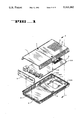
- FIG. 1 is an exploded view of a rigid enclosure of the preferred embodiment.
- FIG. 2 is a detailed view of a single cover as may be utilized by the present invention.
- FIG. 3 is a cutaway view of the back-end side of the covers as may be utilized by the present invention.
- FIG. 4 is a detail view of a height adjustment post as may be utilized by the present invention.
- FIG. 5 is a cutaway view of a fastening means as may be utilized by the present invention.
- PCBs printed circuit boards
- the enclosure housing is comprised of a top cover 1 and a bottom cover 2. Prior to assembly, the top cover 1 and bottom cover 2 are identical; each forming molded long ribs 308 and 305, molded short ribs 307 and 306 (not visible in FIG. 1), front panel ribs 4, fastener holes 5, removable vents 6 and support posts 7. Also shown in FIG. 1 are a PCB 8 and a front panel 9. In the preferred embodiment the solder side of the PCB 8 faces downward while the component side faces upward.
- PCB 8 is illustrative of a PCB that could utilize the present invention. Alternative embodiments could utilize a PCB with different connection means and a corresponding front panel with a different number of connection holes defined.
- the front panel 9 is roughly rectangular in shape. As illustrated in FIG. 1, the front panel 9 defines five (5) thru holes for providing access to connection means located on the PCB 8. Alternative embodiments may have the front panel 9 defining a different number of thru holes without departing from the spirit and scope of the present invention.
- the front panel 9 is positioned within the enclosure by the previously described front panel ribs 4 found on the top cover 1 and bottom cover 2. When assembled, the front panel 9 is inserted into a space defined by a pair of front panel ribs 4. The thickness of the front panel 9 roughly corresponds to the space defined by the front panel ribs 4. Thus, when the front panel 9 is inserted into the space defined by the front panel ribs 4, a secure fit is obtained. When the top cover 1 and bottom cover 2 are fastened together, the front panel 9 is fixed in a stationary position by the front panel ribs 4.
- the front panel 9 is constructed of aluminum and has the dimensions 0.750" ⁇ 3.500" ⁇ 0.062" thick.
- FIG. 2 illustrates the details of a cover 201.
- the cover 2 may be representative of either top cover 1 or bottom cover 2 shown in FIG. 1.
- the cover 201 has rectangular dimensions of 4.00" ⁇ 6.50" and is constructed of plastic. It would be obvious to one skilled in the art, that different dimensions could be utilized without departing from the spirit and scope of the invention.
- An alternative embodiment may use metal cast materials to incorporate the described features.
- the front end 202 of the cover 201 creates an opening where the front panel ribs 4 are defined.
- the front panel ribs 4 are used to align and position the front cover 9.
- two front panel ribs 4 are defined by the cover 201.
- the front panel ribs 4 are approximately 0.080" in width, 0.050" in height and are spaced 0.062" apart. It would be obvious to one skilled in the art, that a different number of front panel ribs or different height, width or spacing could be defined by the cover 201, without departing from the spirit and scope of the present invention.
- the back end 203 forms a curved "L" shaped back and defines a lip 209 at its end.
- the sides 204 also form a curved "L" shape and define a lip 210 at their end.
- the height of the "L" shaped back and sides 203, 204 is 0.550".
- ventilation slots 205 are formed. In the preferred embodiment there are ten (10) ventilation slots formed per side in the front end and nine (9) ventilation slots formed per side in the back end.
- the dimensions of the ventilation slots 205 are 0.125" ⁇ 0.350". It would be obvious to one skilled in the art that the number of ventilation slots per side as well as the location and dimensions of the ventilation slots could vary without departing from the spirit and scope of the present invention.
- alignment means are defined for aligning the top cover 1 with the bottom cover 2 (see FIG. 1).
- the side lip 210 of the cover 201 defines a lengthwise groove 206 and the side lip 211 defines a lengthwise tongue 207.
- the tongue and groove on side lips 209 and 210 meet approximately half way along the width of cover 201.
- Screw guides 208 are formed on the inner surface of the cover 201.
- the fastening holes 5 illustrated in FIG. 1, are formed extending through the screw guides 208.
- the fastening means are described in more detail below.
- a bridge 213 is formed joining the two screw guides 208.
- the bridge 213 provides support and rigidity to the enclosure structure. In the preferred embodiment the height of the bridge 213 is 0.062" and the width is 0.075", the diameter of the fastening hole 5 is 0.150", and the height of screw guide 208 is 0.200".
- the cover 201 has a vent 6 which occupies an opening with dimensions 1.75" ⁇ 1.75". As illustrated in FIG. 1, the vent 6 defines a plurality of openings across it's surface. In the preferred embodiment, the vent 6 defines 88 opening in a 8 ⁇ 11 matrix pattern. The dimension of each opening is 0.070" ⁇ 0.120". Vent 6 is initially molded as part of the top and bottom covers and may be removed by cutting tabs 12 which provides an opening in the bottom cover. When the vent 6 remains in the cover 201, vent 6 provides for circulation of air onto the enclosed PCB 8 and prevents inadvertent or undesired contact with the PCB 8, from outside the enclosure housing. When vent 6 is removed from the cover 201, an opening is provided which allows interface with the PC board inside.
- removable vent 6 is square in shape and has the dimensions 1.600" ⁇ 1.600" and is constructed of plastic. Alternative embodiments of different shapes, construction or fastening means would be obvious to one skilled in the art and would not depart from the spirt and scope of the invention.
- FIG. 3 is a cut-away view of the back-end 203 of the present invention.
- the top cover 1 forms molded ribs 301-304.
- the bottom cover 2 forms molded ribs 305-308.
- two types of molded ribs are formed; long ribs (302, 303, 305, 308) and a short ribs (301, 304, 306, 307).
- the molded ribs are formed so that on the left side of the top cover 1, the short rib 301 is the forward rib and the long rib 302 is the back rib while on the right side the long rib 303 is the forward rib and the short rib 304 is the back rib.
- the long rib 305 is the forward rib and the short rib 306 is the back rib while on the right side, short rib 307 is the front rib and long rib 308 is the back rib.
- a long rib will be aligned with a short rib.
- top cover 1 was turned upside-down, top cover 1 would have the identical rib orientation as bottom cover 2, thus aiding the ability to use identical covers.
- Rectangular notches 309, 310 formed by the PCB 8 define clearance thruways for the long ribs 305, 308 formed by bottom cover 2.
- the rectangular notches 309, 310 are of the dimensions 0.10" ⁇ 0.12" which are roughly equivalent to the dimensions of the long rib 302.
- Notch 309 is defined on the left corner end of the PCB 8 and the notch 310 is defined on the right side approximately 0.20" from the end.
- the long ribs 302, 303 of the top cover 1 work with the corresponding short ribs 306, 307 of the bottom cover 2 to pinch the PCB 8 and provide support.
- the dimensions of the long ribs 302, 303, 305, 308 are 0.075" ⁇ 0.125" ⁇ 0.575" and the dimensions of the short ribs 301, 304, 306, 307 are 0.075" ⁇ 0.125" ⁇ 0.215".
- the front ribs 301, 303, 305, 307 are defined 0.250" from the back-end.
- the back ribs 302, 304,306, 308 are defined 0.475" from the back-end and 0.225" from a front rib. It would be obvious to one skilled in the art that increasing the number of ribs or varying the length would not depart from the spirt and scope of the present invention.
- FIG. 4 is a cross sectional view of a support post 7 in an assembled enclosure. As illustrated in FIG. 1, in the preferred embodiment the posts 7 are formed adjacent to the vent hole 11. The support posts 7 are used to support a PCB 8 adjacent to opening 11. Referring back to FIG. 4, the support posts 7 have a rectangular shaped base with surface posts 403 on each side. A dome shaped protrusion 401 extends from the middle of the base 402 between and extending above the surface posts 403. The unmodified support post 7 is shaped like the top half of the letter "H" with a dome extended past the top legs of the "H".
- Support posts 7 are initially molded with the dome 401 in the top cover 1 and bottom cover 2.
- a modified support post 404 is created when the dome shaped protrusion 401 is removed.
- the support posts 7 are constructed so that the dome shaped protrusion 401 can be removed, for example by breaking it away, without damaging the surface posts 403 or the base 402. The removal is done upon assembly.
- the support post 7 is not modified, the PCB 8 sits atop the domed shaped protrusion 401.
- the support post 7 When the support post 7 is modified, the PCB 8 sits atop the domed surface posts 403.
- the height of the unmodified support post is 0.550"
- the dimension of the base is 0.190
- the height of the surface posts are 0.360" and its thickness is 0.060". It would be obvious to one skilled in the art that a support post could be located elsewhere on the cover as required for PCB support or that the support posts can be of different dimensions.
- FIG. 5 illustrates the means for fastening top cover 1 with bottom cover 2 and PCB 8 when the PCB 8 does not sit on the center horizontal plane of the enclosure.
- a threaded insert 501 is placed in each of the screw guides 208 of the top cover 1. The threaded insert 501 provides a termination point for the screws used by the fastening means.
- a male/female threaded standoff 502 is placed between the fastening holes 10 defined by PCB 8 (as shown in FIG. 1) and the screw guide 208 of the top cover 1. The threaded standoff 502 acts as a spacer to accommodate the horizontal positioning of PCB 8 within the enclosure.
- the threaded standoff 502 and threaded insert 501 provide the means by which fastening can be accomplished and accommodate the PCB offset even though the top and bottom covers are identical.
- the threaded standoff 502 and threaded insert 501 are constructed of steel.
- Two (2) screws 503 originate in the fastening holes 5 defined by the bottom cover 2 extend through the screw guide 208 of the bottom cover 2, the holes 10 defined by PCB 8, and into the threaded standoff 502.
- the top cover 1 may be fastened to the bottom cover 2.
- alternative means to fasten the top and bottom covers together could be employed, e.g. utilizing posts and post holes, without departing from the scope and spirit of the present invention.
- two (2) #6 screws are utilized.
Abstract
Description
Claims (10)
Priority Applications (1)
| Application Number | Priority Date | Filing Date | Title |
|---|---|---|---|
| US07/584,190 US5111362A (en) | 1990-09-18 | 1990-09-18 | Enclosure assembly with two identical covers having modifiable supports for asymmetrically housing a printed circuit board or the like |
Applications Claiming Priority (1)
| Application Number | Priority Date | Filing Date | Title |
|---|---|---|---|
| US07/584,190 US5111362A (en) | 1990-09-18 | 1990-09-18 | Enclosure assembly with two identical covers having modifiable supports for asymmetrically housing a printed circuit board or the like |
Publications (1)
| Publication Number | Publication Date |
|---|---|
| US5111362A true US5111362A (en) | 1992-05-05 |
Family
ID=24336272
Family Applications (1)
| Application Number | Title | Priority Date | Filing Date |
|---|---|---|---|
| US07/584,190 Expired - Lifetime US5111362A (en) | 1990-09-18 | 1990-09-18 | Enclosure assembly with two identical covers having modifiable supports for asymmetrically housing a printed circuit board or the like |
Country Status (1)
| Country | Link |
|---|---|
| US (1) | US5111362A (en) |
Cited By (75)
| Publication number | Priority date | Publication date | Assignee | Title |
|---|---|---|---|---|
| US5310070A (en) * | 1991-10-01 | 1994-05-10 | Franz Haas Waffelmaschinen Industriegesellschaft M.B.H. | Container of readily biodegradable material |
| US5369549A (en) * | 1992-12-16 | 1994-11-29 | Hewlett-Packard Company | Casing for a device |
| US5386340A (en) * | 1993-08-13 | 1995-01-31 | Kurz; Arthur A. | Enclosure for personal computer card GPT |
| US5398833A (en) * | 1991-03-13 | 1995-03-21 | Siemens Nixdorf Informationssysteme Aktiengesellschaft | Device for contact between a case bottom and cover of a closed housing |
| WO1995022181A1 (en) * | 1994-02-15 | 1995-08-17 | Berg Technology, Inc. | Shielded circuit board connector module |
| US5446622A (en) * | 1993-08-06 | 1995-08-29 | Digital Equipment Corporation | PC board cartridge for a computer terminal |
| US5473509A (en) * | 1992-09-24 | 1995-12-05 | Siemens Aktiengesellschaft | Electronic control unit |
| US5477421A (en) * | 1993-11-18 | 1995-12-19 | Itt Corporation | Shielded IC card |
| US5481434A (en) * | 1993-10-04 | 1996-01-02 | Molex Incorporated | Memory card and frame for assembly therefor |
| US5526234A (en) * | 1992-07-17 | 1996-06-11 | Vlt Corporation | Packaging electrical components |
| US5526929A (en) * | 1995-03-30 | 1996-06-18 | Wei; Yong L. | Tool box with a cover, a base and a plate disposed between the cover and the base |
| US5644103A (en) * | 1994-11-10 | 1997-07-01 | Vlt Corporation | Packaging electrical components having a scallop formed in an edge of a circuit board |
| US5691881A (en) * | 1995-05-16 | 1997-11-25 | Hewlett-Packard Company | Electronic device having E-PAC chassis for spatial arrangement of components and cable organization including channel with retaining wall preventing cable from dislodging from an edge connector |
| WO1997046065A1 (en) * | 1996-05-29 | 1997-12-04 | Ut Automotive Dearborn, Inc. | Assembly for housing electrical components and a circuit board |
| US5754643A (en) * | 1995-10-02 | 1998-05-19 | Lucent Technologies Inc. | Weatherable outside electronic device enclosure |
| US5782370A (en) * | 1996-08-08 | 1998-07-21 | Nec Corporation | Casing capable of protecting an electronic apparatus from static electricity |
| US5967785A (en) * | 1996-06-12 | 1999-10-19 | Funai Electric Co. Ltd. | Cable holder and cable fixing method |
| US6027535A (en) * | 1996-02-27 | 2000-02-22 | Metabowerke Gmbh & Co. | Battery charger for power tools |
| US6039600A (en) * | 1997-10-10 | 2000-03-21 | Molex Incorporated | Male connector for flat flexible circuit |
| US6181564B1 (en) * | 1998-06-26 | 2001-01-30 | Alps Electric Co., Ltd. | IC card |
| US6185100B1 (en) * | 1996-01-10 | 2001-02-06 | Robert Bosch Gmbh | Control device consisting of at least two housing sections |
| US6215669B1 (en) * | 1999-02-10 | 2001-04-10 | Methode Electronics, Inc. | Discrete component in-mold mounting |
| US6217377B1 (en) | 1996-12-09 | 2001-04-17 | The Furukawa Electric Co., Ltd. | Electric circuit connection container |
| US6249442B1 (en) * | 1998-11-25 | 2001-06-19 | Alps Electric Co., Ltd | Structure for mounting two printed circuit boards to one case |
| DE10001204C1 (en) * | 2000-01-14 | 2001-09-06 | Bopla Gehaeuse Systeme Gmbh | Electrical and/or electronic component housing assembled from two identical U-shaped housing parts with rotational symmetry about two orthogonal axes |
| US6307752B1 (en) | 1999-12-30 | 2001-10-23 | Hubbell Incorporated | Housing for electrical device with relief for shearable ribs |
| US6309257B1 (en) * | 2000-08-09 | 2001-10-30 | Shining Blick Enterprises Co., Ltd. | Sealed, water-proof housing for an electrical device |
| US6316737B1 (en) | 1999-09-09 | 2001-11-13 | Vlt Corporation | Making a connection between a component and a circuit board |
| US6386891B1 (en) | 2000-12-28 | 2002-05-14 | Hubbell Incorporated | Multiport assembly having a floating electrical circuit board within an enclosure assembly |
| US6426882B1 (en) * | 2001-11-21 | 2002-07-30 | Infocus Systems, Inc. | Housing for electronic components |
| US6462958B2 (en) * | 2000-05-09 | 2002-10-08 | Sony Computer Entertainment, Inc. | Shielded and grounded electronic device |
| US6501015B2 (en) * | 2001-01-22 | 2002-12-31 | Marconi Communications, Inc. | Vented cap for equipment pedestal |
| US20030013329A1 (en) * | 2001-07-14 | 2003-01-16 | Andre Koerner | Housing with an electrical circuit accommodated therein |
| US6519841B1 (en) * | 1999-06-15 | 2003-02-18 | Geneticware Co., Ltd. | Method of IC packing/unpacking for preserving and updating data within the IC and the structure thereof |
| US6549409B1 (en) | 2000-08-21 | 2003-04-15 | Vlt Corporation | Power converter assembly |
| US20030147204A1 (en) * | 2002-02-06 | 2003-08-07 | Keihin Corporation | Electronic circuit board case |
| US20030156392A1 (en) * | 1999-01-29 | 2003-08-21 | Henson Walter Herbert | Secure housing |
| US6650545B1 (en) * | 1999-09-06 | 2003-11-18 | Sony Computer Entertainment Inc. | Cabinet of electronic device for housing electronic components and electronic device having the cabinet |
| US6678874B1 (en) * | 2001-11-28 | 2004-01-13 | Unisys Corporation | Computer-aided design (CAD) tool |
| US6688911B2 (en) | 2000-12-13 | 2004-02-10 | Molex Incorporated | Electrical connector assembly for flat flexible circuitry |
| US20040125571A1 (en) * | 2002-12-27 | 2004-07-01 | Hitron Technologies | Modular housing structure for modem |
| US20040160714A1 (en) * | 2001-04-24 | 2004-08-19 | Vlt Corporation, A Texas Corporation | Components having actively controlled circuit elements |
| US20040264113A1 (en) * | 2003-06-30 | 2004-12-30 | Darr Christopher J. | Smart junction box for automobile |
| WO2005009097A1 (en) * | 2003-07-23 | 2005-01-27 | Siemens Vdo Automotive | Housing, in particular housing for electronic components or the like |
| US20050071290A1 (en) * | 2003-09-30 | 2005-03-31 | Pitney Bowes Incorporated | Mailing machine with a repositionable user controller |
| US20050243506A1 (en) * | 2004-05-03 | 2005-11-03 | Robertson Kenneth G | Removable information storage device enclosure |
| US20070097604A1 (en) * | 2005-10-28 | 2007-05-03 | Bruski Gary P | Arc resistant baffle for reducing arc-flash energy in an electrical enclosure |
| US20070159800A1 (en) * | 2006-01-10 | 2007-07-12 | Funai Electric Co., Ltd. | Cabinet for electric apparatus |
| US20070211441A1 (en) * | 2006-03-10 | 2007-09-13 | Amf Technology, Inc. | Container for electronic components |
| US20070223202A1 (en) * | 2004-09-17 | 2007-09-27 | Ntt Docomo, Inc. | Planar circuit housing |
| US20080218037A1 (en) * | 2007-03-06 | 2008-09-11 | Sanyo Electric Co., Ltd. | Holding structure and projection display device |
| US7443229B1 (en) | 2001-04-24 | 2008-10-28 | Picor Corporation | Active filtering |
| US20080298028A1 (en) * | 2007-05-31 | 2008-12-04 | Matthew Travers | Amc carrier faceplates |
| US20090166096A1 (en) * | 2007-03-31 | 2009-07-02 | Robert Hansen | Weighing indicator and housing |
| US20090267465A1 (en) * | 2008-04-25 | 2009-10-29 | King Young Technology Co., Ltd. | Microcomputer case |
| US20090316377A1 (en) * | 2007-01-09 | 2009-12-24 | Continental Automotive Gmbh | Mounting arrangement for fixing printed circuit boards disposed one above the other in a housing |
| US20100044008A1 (en) * | 2008-08-20 | 2010-02-25 | Michael Drummy | Portable environmentally robust enclosure optimized for size, weight, and power dissipation |
| US20100105221A1 (en) * | 2008-10-28 | 2010-04-29 | Sumitomo Wiring Systems, Ltd. | Electrical connection box and method of assembling the electrical connection box |
| US20100181324A1 (en) * | 2006-01-31 | 2010-07-22 | Shi Mechanical & Equipment Inc. | Seal Structure of Pressure Vessel |
| DE102009008527A1 (en) * | 2009-02-11 | 2010-08-12 | Continental Automotive Gmbh | Electronic device for use as carriers of e.g. sensors, in automotive engineering field, has group of ridge-shaped moldings pressed such that exposed end of moldings press plate in direction of base of housing |
| US20120034815A1 (en) * | 2009-04-15 | 2012-02-09 | Yazaki Corporation | Connector |
| WO2012024423A3 (en) * | 2010-08-18 | 2012-05-03 | Egs Electrical Group, Llc | Sealed circuit breaker |
| US8210356B1 (en) * | 2009-08-14 | 2012-07-03 | Krull Mark A | Organizational methods and apparatus |
| US20140111069A1 (en) * | 2012-10-22 | 2014-04-24 | Comptake Technology Inc. | Housing structure for solid-state drive |
| US20140110163A1 (en) * | 2011-06-22 | 2014-04-24 | Nozomi Etsumi | Substrate case structure |
| US8817455B2 (en) | 2008-08-06 | 2014-08-26 | Egs Electrical Group, Llc | Sealed circuit breaker |
| US20150156896A1 (en) * | 2013-12-04 | 2015-06-04 | Lsis Co., Ltd. | Electric device for electric vehicle |
| US9541967B1 (en) * | 2015-08-12 | 2017-01-10 | Comptake Technology Inc. | Hard disk and housing thereof |
| US20180014418A1 (en) * | 2015-03-26 | 2018-01-11 | Continental Automotive Gmbh | Electronic Control Unit with a Housing Stabilizing Element and Housing for Electronic Control Unit |
| GB2559683A (en) * | 2016-11-11 | 2018-08-15 | Shenzhen Ivps Tech Co Ltd | Fixing structure and electronic cigarette having same |
| CN110831365A (en) * | 2018-08-10 | 2020-02-21 | 泰连德国有限公司 | Assembly with printed circuit board and method for fixing printed circuit board |
| USD888000S1 (en) * | 2018-08-29 | 2020-06-23 | Samsung Electronics Co., Ltd. | Case for a circuit board |
| WO2021150247A1 (en) * | 2020-01-24 | 2021-07-29 | Hewlett-Packard Development Company, L.P. | Electronic device mounting screw assemblies |
| US20220169190A1 (en) * | 2019-03-05 | 2022-06-02 | Autonetworks Technologies, Ltd. | Wiring harness unit and wiring harness mounting structure |
| US20220181858A1 (en) * | 2019-03-05 | 2022-06-09 | Autonetworks Technologies, Ltd. | Wiring harness module and wiring harness routing device |
Citations (16)
| Publication number | Priority date | Publication date | Assignee | Title |
|---|---|---|---|---|
| US3264534A (en) * | 1964-04-21 | 1966-08-02 | Vitramon Inc | Electrical component and thermal construction |
| US3407869A (en) * | 1967-01-16 | 1968-10-29 | Perkin Elmer Corp | Instrument cooling system |
| US3407961A (en) * | 1966-04-13 | 1968-10-29 | Box Theodor | Plastic poultry crate and the like |
| US3631299A (en) * | 1970-05-21 | 1971-12-28 | Square D Co | Printed circuit board module and support with circuit board supporting posts |
| US3952903A (en) * | 1974-10-21 | 1976-04-27 | Pinckney Molded Plastics, Inc. | Closed container |
| US4652969A (en) * | 1985-07-05 | 1987-03-24 | Racal Data Communications Inc. | Secure universal housing arrangement for enclosing electronic circuits |
| US4664254A (en) * | 1984-06-06 | 1987-05-12 | Sitwell Christine L | Shipping container for works of art |
| US4695925A (en) * | 1985-09-30 | 1987-09-22 | Mitsubishi Denki Kabushiki Kaisha | IC card |
| US4700275A (en) * | 1986-06-23 | 1987-10-13 | Tektronix, Inc. | Modularized electronic instrument packaging system |
| US4840286A (en) * | 1988-02-23 | 1989-06-20 | Hayes Microcomputer Products, Inc. | Equipment enclosure with internal fasteners |
| US4889542A (en) * | 1988-11-14 | 1989-12-26 | Hayes William J | Computer air filter device and method |
| US4916575A (en) * | 1988-08-08 | 1990-04-10 | Asten Francis C Van | Multiple circuit board module |
| US4918572A (en) * | 1988-12-27 | 1990-04-17 | Motorola Computer X, Inc. | Modular electronic package |
| US4958259A (en) * | 1986-09-30 | 1990-09-18 | Rittal-Werk Rudolf Loh Gmbh & Co., Kg | Multi-purpose housing |
| US5002493A (en) * | 1989-09-19 | 1991-03-26 | Amp Incorporated | Panel mounted electronic assembly |
| US5054418A (en) * | 1989-05-23 | 1991-10-08 | Union Oil Company Of California | Cage boat having removable slats |
-
1990
- 1990-09-18 US US07/584,190 patent/US5111362A/en not_active Expired - Lifetime
Patent Citations (16)
| Publication number | Priority date | Publication date | Assignee | Title |
|---|---|---|---|---|
| US3264534A (en) * | 1964-04-21 | 1966-08-02 | Vitramon Inc | Electrical component and thermal construction |
| US3407961A (en) * | 1966-04-13 | 1968-10-29 | Box Theodor | Plastic poultry crate and the like |
| US3407869A (en) * | 1967-01-16 | 1968-10-29 | Perkin Elmer Corp | Instrument cooling system |
| US3631299A (en) * | 1970-05-21 | 1971-12-28 | Square D Co | Printed circuit board module and support with circuit board supporting posts |
| US3952903A (en) * | 1974-10-21 | 1976-04-27 | Pinckney Molded Plastics, Inc. | Closed container |
| US4664254A (en) * | 1984-06-06 | 1987-05-12 | Sitwell Christine L | Shipping container for works of art |
| US4652969A (en) * | 1985-07-05 | 1987-03-24 | Racal Data Communications Inc. | Secure universal housing arrangement for enclosing electronic circuits |
| US4695925A (en) * | 1985-09-30 | 1987-09-22 | Mitsubishi Denki Kabushiki Kaisha | IC card |
| US4700275A (en) * | 1986-06-23 | 1987-10-13 | Tektronix, Inc. | Modularized electronic instrument packaging system |
| US4958259A (en) * | 1986-09-30 | 1990-09-18 | Rittal-Werk Rudolf Loh Gmbh & Co., Kg | Multi-purpose housing |
| US4840286A (en) * | 1988-02-23 | 1989-06-20 | Hayes Microcomputer Products, Inc. | Equipment enclosure with internal fasteners |
| US4916575A (en) * | 1988-08-08 | 1990-04-10 | Asten Francis C Van | Multiple circuit board module |
| US4889542A (en) * | 1988-11-14 | 1989-12-26 | Hayes William J | Computer air filter device and method |
| US4918572A (en) * | 1988-12-27 | 1990-04-17 | Motorola Computer X, Inc. | Modular electronic package |
| US5054418A (en) * | 1989-05-23 | 1991-10-08 | Union Oil Company Of California | Cage boat having removable slats |
| US5002493A (en) * | 1989-09-19 | 1991-03-26 | Amp Incorporated | Panel mounted electronic assembly |
Cited By (109)
| Publication number | Priority date | Publication date | Assignee | Title |
|---|---|---|---|---|
| US5398833A (en) * | 1991-03-13 | 1995-03-21 | Siemens Nixdorf Informationssysteme Aktiengesellschaft | Device for contact between a case bottom and cover of a closed housing |
| DE4232895C2 (en) * | 1991-10-01 | 2002-01-31 | Haas Franz Waffelmasch | Container made of easily rotten material |
| US5310070A (en) * | 1991-10-01 | 1994-05-10 | Franz Haas Waffelmaschinen Industriegesellschaft M.B.H. | Container of readily biodegradable material |
| US5526234A (en) * | 1992-07-17 | 1996-06-11 | Vlt Corporation | Packaging electrical components |
| US5778526A (en) * | 1992-07-17 | 1998-07-14 | Vlt Corporation | Packaging electrical components |
| US5663869A (en) * | 1992-07-17 | 1997-09-02 | Vlt Corporation | Packaging electrical components |
| US5473509A (en) * | 1992-09-24 | 1995-12-05 | Siemens Aktiengesellschaft | Electronic control unit |
| US5671122A (en) * | 1992-09-24 | 1997-09-23 | Siemens Akitiengesellschaft | Electronic control unit |
| US5369549A (en) * | 1992-12-16 | 1994-11-29 | Hewlett-Packard Company | Casing for a device |
| US5446622A (en) * | 1993-08-06 | 1995-08-29 | Digital Equipment Corporation | PC board cartridge for a computer terminal |
| US5386340A (en) * | 1993-08-13 | 1995-01-31 | Kurz; Arthur A. | Enclosure for personal computer card GPT |
| US5481434A (en) * | 1993-10-04 | 1996-01-02 | Molex Incorporated | Memory card and frame for assembly therefor |
| US5477421A (en) * | 1993-11-18 | 1995-12-19 | Itt Corporation | Shielded IC card |
| US5745349A (en) * | 1994-02-15 | 1998-04-28 | Berg Technology, Inc. | Shielded circuit board connector module |
| WO1995022181A1 (en) * | 1994-02-15 | 1995-08-17 | Berg Technology, Inc. | Shielded circuit board connector module |
| US6081431A (en) * | 1994-02-15 | 2000-06-27 | Berg Technology, Inc. | Shielded circuit board connector module |
| US5644103A (en) * | 1994-11-10 | 1997-07-01 | Vlt Corporation | Packaging electrical components having a scallop formed in an edge of a circuit board |
| US5526929A (en) * | 1995-03-30 | 1996-06-18 | Wei; Yong L. | Tool box with a cover, a base and a plate disposed between the cover and the base |
| US5691881A (en) * | 1995-05-16 | 1997-11-25 | Hewlett-Packard Company | Electronic device having E-PAC chassis for spatial arrangement of components and cable organization including channel with retaining wall preventing cable from dislodging from an edge connector |
| CN1107440C (en) * | 1995-05-16 | 2003-04-30 | 艾加伦特技术公司 | Electronic device having E-PAC chassis for spatial arrangement of components and cable organization |
| US5754643A (en) * | 1995-10-02 | 1998-05-19 | Lucent Technologies Inc. | Weatherable outside electronic device enclosure |
| US6185100B1 (en) * | 1996-01-10 | 2001-02-06 | Robert Bosch Gmbh | Control device consisting of at least two housing sections |
| US6027535A (en) * | 1996-02-27 | 2000-02-22 | Metabowerke Gmbh & Co. | Battery charger for power tools |
| US5761047A (en) * | 1996-05-29 | 1998-06-02 | Ut Automotive Dearborn, Inc. | Retaining support for electrical assembly having ribs extending from housing |
| WO1997046065A1 (en) * | 1996-05-29 | 1997-12-04 | Ut Automotive Dearborn, Inc. | Assembly for housing electrical components and a circuit board |
| US5967785A (en) * | 1996-06-12 | 1999-10-19 | Funai Electric Co. Ltd. | Cable holder and cable fixing method |
| CN1130798C (en) * | 1996-06-12 | 2003-12-10 | 船井电机株式会社 | Cable holder and cable fixing method |
| US5782370A (en) * | 1996-08-08 | 1998-07-21 | Nec Corporation | Casing capable of protecting an electronic apparatus from static electricity |
| US6217377B1 (en) | 1996-12-09 | 2001-04-17 | The Furukawa Electric Co., Ltd. | Electric circuit connection container |
| US6039600A (en) * | 1997-10-10 | 2000-03-21 | Molex Incorporated | Male connector for flat flexible circuit |
| US6181564B1 (en) * | 1998-06-26 | 2001-01-30 | Alps Electric Co., Ltd. | IC card |
| US6249442B1 (en) * | 1998-11-25 | 2001-06-19 | Alps Electric Co., Ltd | Structure for mounting two printed circuit boards to one case |
| US20030156392A1 (en) * | 1999-01-29 | 2003-08-21 | Henson Walter Herbert | Secure housing |
| US6898077B2 (en) * | 1999-01-29 | 2005-05-24 | Neopost Limited | Secure housing |
| US6215669B1 (en) * | 1999-02-10 | 2001-04-10 | Methode Electronics, Inc. | Discrete component in-mold mounting |
| US6519841B1 (en) * | 1999-06-15 | 2003-02-18 | Geneticware Co., Ltd. | Method of IC packing/unpacking for preserving and updating data within the IC and the structure thereof |
| US6650545B1 (en) * | 1999-09-06 | 2003-11-18 | Sony Computer Entertainment Inc. | Cabinet of electronic device for housing electronic components and electronic device having the cabinet |
| US6316737B1 (en) | 1999-09-09 | 2001-11-13 | Vlt Corporation | Making a connection between a component and a circuit board |
| US6307752B1 (en) | 1999-12-30 | 2001-10-23 | Hubbell Incorporated | Housing for electrical device with relief for shearable ribs |
| DE10001204C1 (en) * | 2000-01-14 | 2001-09-06 | Bopla Gehaeuse Systeme Gmbh | Electrical and/or electronic component housing assembled from two identical U-shaped housing parts with rotational symmetry about two orthogonal axes |
| US6462958B2 (en) * | 2000-05-09 | 2002-10-08 | Sony Computer Entertainment, Inc. | Shielded and grounded electronic device |
| US6309257B1 (en) * | 2000-08-09 | 2001-10-30 | Shining Blick Enterprises Co., Ltd. | Sealed, water-proof housing for an electrical device |
| US6549409B1 (en) | 2000-08-21 | 2003-04-15 | Vlt Corporation | Power converter assembly |
| US6688911B2 (en) | 2000-12-13 | 2004-02-10 | Molex Incorporated | Electrical connector assembly for flat flexible circuitry |
| US7025626B2 (en) | 2000-12-13 | 2006-04-11 | Molex Incorporated | Electrical connector assembly for flat flexible circuitry |
| US20050153595A1 (en) * | 2000-12-13 | 2005-07-14 | Fuerst Robert M. | Electrical connector assembly for flat flexible circuitry |
| US6386891B1 (en) | 2000-12-28 | 2002-05-14 | Hubbell Incorporated | Multiport assembly having a floating electrical circuit board within an enclosure assembly |
| US6501015B2 (en) * | 2001-01-22 | 2002-12-31 | Marconi Communications, Inc. | Vented cap for equipment pedestal |
| US7443229B1 (en) | 2001-04-24 | 2008-10-28 | Picor Corporation | Active filtering |
| US6985341B2 (en) | 2001-04-24 | 2006-01-10 | Vlt, Inc. | Components having actively controlled circuit elements |
| US20040160714A1 (en) * | 2001-04-24 | 2004-08-19 | Vlt Corporation, A Texas Corporation | Components having actively controlled circuit elements |
| US7944273B1 (en) | 2001-04-24 | 2011-05-17 | Picor Corporation | Active filtering |
| US6719571B2 (en) * | 2001-07-14 | 2004-04-13 | Hella Kg Hueck & Co. | Housing with an electrical circuit accommodated therein |
| US20030013329A1 (en) * | 2001-07-14 | 2003-01-16 | Andre Koerner | Housing with an electrical circuit accommodated therein |
| US6426882B1 (en) * | 2001-11-21 | 2002-07-30 | Infocus Systems, Inc. | Housing for electronic components |
| US6678874B1 (en) * | 2001-11-28 | 2004-01-13 | Unisys Corporation | Computer-aided design (CAD) tool |
| US6757155B2 (en) * | 2002-02-06 | 2004-06-29 | Keihin Corporation | Electronic circuit board case |
| US20030147204A1 (en) * | 2002-02-06 | 2003-08-07 | Keihin Corporation | Electronic circuit board case |
| US20040125571A1 (en) * | 2002-12-27 | 2004-07-01 | Hitron Technologies | Modular housing structure for modem |
| US6967846B2 (en) * | 2002-12-27 | 2005-11-22 | Hitron Technologies | Modular housing structure for modem |
| US6894891B2 (en) * | 2003-06-30 | 2005-05-17 | Lear Corporation | Smart junction box for automobile |
| US20040264113A1 (en) * | 2003-06-30 | 2004-12-30 | Darr Christopher J. | Smart junction box for automobile |
| WO2005009097A1 (en) * | 2003-07-23 | 2005-01-27 | Siemens Vdo Automotive | Housing, in particular housing for electronic components or the like |
| US20070103852A1 (en) * | 2003-07-23 | 2007-05-10 | Siemens Vdo Automotive | Housing, in particular housing for electronic components or the like |
| US7511963B2 (en) | 2003-07-23 | 2009-03-31 | Continental Automotive France | Housing, in particular housing for electronic components or the like |
| FR2858169A1 (en) * | 2003-07-23 | 2005-01-28 | Siemens Vdo Automotive | Box for containing electronic component e.g. chip, has side wall equipped with flange and hollow zone whose concavity is oriented towards outside of box, where flange receives fixing screw suspended above hollow zone |
| US20050071290A1 (en) * | 2003-09-30 | 2005-03-31 | Pitney Bowes Incorporated | Mailing machine with a repositionable user controller |
| US7567431B2 (en) * | 2003-09-30 | 2009-07-28 | Pitney Bowes Inc. | Mailing machine with a repositionable user controller |
| US20050243506A1 (en) * | 2004-05-03 | 2005-11-03 | Robertson Kenneth G | Removable information storage device enclosure |
| US20070223202A1 (en) * | 2004-09-17 | 2007-09-27 | Ntt Docomo, Inc. | Planar circuit housing |
| US7564699B2 (en) * | 2004-09-17 | 2009-07-21 | Ntt Docomo, Inc. | Planar circuit housing |
| US7778013B2 (en) * | 2005-10-28 | 2010-08-17 | Rockwell Automation Technologies, Inc. | Arc resistant baffle for reducing arc-flash energy in an electrical enclosure |
| US20070097604A1 (en) * | 2005-10-28 | 2007-05-03 | Bruski Gary P | Arc resistant baffle for reducing arc-flash energy in an electrical enclosure |
| US20070159800A1 (en) * | 2006-01-10 | 2007-07-12 | Funai Electric Co., Ltd. | Cabinet for electric apparatus |
| US20100181324A1 (en) * | 2006-01-31 | 2010-07-22 | Shi Mechanical & Equipment Inc. | Seal Structure of Pressure Vessel |
| US20070211441A1 (en) * | 2006-03-10 | 2007-09-13 | Amf Technology, Inc. | Container for electronic components |
| US20090316377A1 (en) * | 2007-01-09 | 2009-12-24 | Continental Automotive Gmbh | Mounting arrangement for fixing printed circuit boards disposed one above the other in a housing |
| US8027164B2 (en) * | 2007-01-09 | 2011-09-27 | Continental Automotive Gmbh | Mounting arrangement for fixing printed circuit boards disposed one above the other in a housing |
| US20080218037A1 (en) * | 2007-03-06 | 2008-09-11 | Sanyo Electric Co., Ltd. | Holding structure and projection display device |
| US7967453B2 (en) * | 2007-03-06 | 2011-06-28 | Sanyo Electric Co., Ltd. | Holding structure for holding a member in an external cabinet |
| US20090166096A1 (en) * | 2007-03-31 | 2009-07-02 | Robert Hansen | Weighing indicator and housing |
| US7795549B2 (en) * | 2007-03-31 | 2010-09-14 | Ohaus Corporation | Weight indicator housing with a top and bottom cover attachable together in more than one configuration |
| US20080298028A1 (en) * | 2007-05-31 | 2008-12-04 | Matthew Travers | Amc carrier faceplates |
| US20090267465A1 (en) * | 2008-04-25 | 2009-10-29 | King Young Technology Co., Ltd. | Microcomputer case |
| US8817455B2 (en) | 2008-08-06 | 2014-08-26 | Egs Electrical Group, Llc | Sealed circuit breaker |
| US7817420B2 (en) * | 2008-08-20 | 2010-10-19 | Olympus Ndt | Portable environmentally robust enclosure optimized for size, weight, and power dissipation |
| US20100044008A1 (en) * | 2008-08-20 | 2010-02-25 | Michael Drummy | Portable environmentally robust enclosure optimized for size, weight, and power dissipation |
| US7815443B2 (en) * | 2008-10-28 | 2010-10-19 | Sumitomo Wiring Systems, Ltd. | Electrical connection box and method of assembling the electrical connection box |
| US20100105221A1 (en) * | 2008-10-28 | 2010-04-29 | Sumitomo Wiring Systems, Ltd. | Electrical connection box and method of assembling the electrical connection box |
| DE102009008527A1 (en) * | 2009-02-11 | 2010-08-12 | Continental Automotive Gmbh | Electronic device for use as carriers of e.g. sensors, in automotive engineering field, has group of ridge-shaped moldings pressed such that exposed end of moldings press plate in direction of base of housing |
| US20120034815A1 (en) * | 2009-04-15 | 2012-02-09 | Yazaki Corporation | Connector |
| US8550841B2 (en) * | 2009-04-15 | 2013-10-08 | Yazaki Corporation | Flat cable connector having cable support structure |
| US8210356B1 (en) * | 2009-08-14 | 2012-07-03 | Krull Mark A | Organizational methods and apparatus |
| WO2012024423A3 (en) * | 2010-08-18 | 2012-05-03 | Egs Electrical Group, Llc | Sealed circuit breaker |
| US8593791B2 (en) | 2010-08-18 | 2013-11-26 | Egs Electrical Group, Llc | Sealed circuit breaker |
| US20140110163A1 (en) * | 2011-06-22 | 2014-04-24 | Nozomi Etsumi | Substrate case structure |
| US20140111069A1 (en) * | 2012-10-22 | 2014-04-24 | Comptake Technology Inc. | Housing structure for solid-state drive |
| US20150156896A1 (en) * | 2013-12-04 | 2015-06-04 | Lsis Co., Ltd. | Electric device for electric vehicle |
| US9485880B2 (en) * | 2013-12-04 | 2016-11-01 | Lsis Co., Ltd. | Electric device for electric vehicle |
| US20180014418A1 (en) * | 2015-03-26 | 2018-01-11 | Continental Automotive Gmbh | Electronic Control Unit with a Housing Stabilizing Element and Housing for Electronic Control Unit |
| US10244645B2 (en) * | 2015-03-26 | 2019-03-26 | Continental Automotive Gmbh | Electronic control unit with a housing stabilizing element and housing for electronic control unit |
| US9541967B1 (en) * | 2015-08-12 | 2017-01-10 | Comptake Technology Inc. | Hard disk and housing thereof |
| GB2559683A (en) * | 2016-11-11 | 2018-08-15 | Shenzhen Ivps Tech Co Ltd | Fixing structure and electronic cigarette having same |
| GB2559683B (en) * | 2016-11-11 | 2021-03-31 | Shenzhen Ivps Tech Co Ltd | Fixing structure and electronic cigarette having same |
| CN110831365A (en) * | 2018-08-10 | 2020-02-21 | 泰连德国有限公司 | Assembly with printed circuit board and method for fixing printed circuit board |
| USD888000S1 (en) * | 2018-08-29 | 2020-06-23 | Samsung Electronics Co., Ltd. | Case for a circuit board |
| US20220169190A1 (en) * | 2019-03-05 | 2022-06-02 | Autonetworks Technologies, Ltd. | Wiring harness unit and wiring harness mounting structure |
| US20220181858A1 (en) * | 2019-03-05 | 2022-06-09 | Autonetworks Technologies, Ltd. | Wiring harness module and wiring harness routing device |
| WO2021150247A1 (en) * | 2020-01-24 | 2021-07-29 | Hewlett-Packard Development Company, L.P. | Electronic device mounting screw assemblies |
Similar Documents
| Publication | Publication Date | Title |
|---|---|---|
| US5111362A (en) | Enclosure assembly with two identical covers having modifiable supports for asymmetrically housing a printed circuit board or the like | |
| US5677830A (en) | Modular, stacking, expandable electronic enclosure system | |
| FI85204B (en) | KONSTRUKTION FOER RADIOTELEFON ELLER MANOEVERANORDNING TILL EN RADIOTELEFON. | |
| US6644979B2 (en) | Backplane structure capable of being mounted with two interface cards | |
| EP0468661B1 (en) | Apparatus for mechanically and electrically connecting printed circuits boards | |
| US3733523A (en) | Electronic circuit card cage | |
| US4109300A (en) | Circuit card connector and support device | |
| US7133288B2 (en) | Processor heat sink retention module and assembly | |
| US5898412A (en) | Transmit/receive antenna mounting enclosure | |
| US8038451B2 (en) | Multi-board printed circuit assembly having aligned connectors | |
| US7252544B2 (en) | Connector having a U-shaped fixing member with screw holes | |
| US5034853A (en) | Housing, particularly a module carrier, including supporting rails for accomodating a plurality of mutually parallel guide rails | |
| US6137689A (en) | Protective enclosure apparatus and method | |
| US6201709B1 (en) | Mounting system to support electrical components in a stacked relationship to one another | |
| US5969946A (en) | Heat dissipating electrical apparatus | |
| US6614657B2 (en) | Heat sink for cooling an electronic component of a computer | |
| US4034871A (en) | Adapter for mounting printed circuit cards | |
| GB2111758A (en) | Plug in module connector mount | |
| JP2693251B2 (en) | Power cooling module | |
| JP2524262Y2 (en) | Right angle connector | |
| CN216218184U (en) | Light-adjusting film power supply assembly | |
| CN215268559U (en) | Television box assembling structure | |
| EP1180922A2 (en) | A mount shelf for electronic circuit boards, which has an excellent air permeability and also has an excellent radiation performance with regard to a heat generated by a part of the electronic circuit | |
| JPH11145650A (en) | Printed board fixing structure | |
| KR880003259Y1 (en) | Tuner holder |
Legal Events
| Date | Code | Title | Description |
|---|---|---|---|
| AS | Assignment |
Owner name: INTEL CORPORATION, 3065 BOWERS AVENUE, SANTA CLARA Free format text: ASSIGNMENT OF ASSIGNORS INTEREST.;ASSIGNORS:FLAMM, RONALD C.;TURNER, LEONARD O.;PLUNKETT, JAMES D.;REEL/FRAME:005492/0090 Effective date: 19900913 |
|
| STCF | Information on status: patent grant |
Free format text: PATENTED CASE |
|
| CC | Certificate of correction | ||
| FEPP | Fee payment procedure |
Free format text: PAYOR NUMBER ASSIGNED (ORIGINAL EVENT CODE: ASPN); ENTITY STATUS OF PATENT OWNER: LARGE ENTITY |
|
| FPAY | Fee payment |
Year of fee payment: 4 |
|
| FPAY | Fee payment |
Year of fee payment: 8 |
|
| FPAY | Fee payment |
Year of fee payment: 12 |