US5103667A - Self-testable micro-accelerometer and method - Google Patents
Self-testable micro-accelerometer and method Download PDFInfo
- Publication number
- US5103667A US5103667A US07/370,364 US37036489A US5103667A US 5103667 A US5103667 A US 5103667A US 37036489 A US37036489 A US 37036489A US 5103667 A US5103667 A US 5103667A
- Authority
- US
- United States
- Prior art keywords
- mass
- accelerometer
- housing
- output
- differential amplifier
- Prior art date
- Legal status (The legal status is an assumption and is not a legal conclusion. Google has not performed a legal analysis and makes no representation as to the accuracy of the status listed.)
- Expired - Fee Related
Links
Images


Classifications
-
- G—PHYSICS
- G01—MEASURING; TESTING
- G01P—MEASURING LINEAR OR ANGULAR SPEED, ACCELERATION, DECELERATION, OR SHOCK; INDICATING PRESENCE, ABSENCE, OR DIRECTION, OF MOVEMENT
- G01P15/00—Measuring acceleration; Measuring deceleration; Measuring shock, i.e. sudden change of acceleration
- G01P15/02—Measuring acceleration; Measuring deceleration; Measuring shock, i.e. sudden change of acceleration by making use of inertia forces using solid seismic masses
- G01P15/08—Measuring acceleration; Measuring deceleration; Measuring shock, i.e. sudden change of acceleration by making use of inertia forces using solid seismic masses with conversion into electric or magnetic values
- G01P15/12—Measuring acceleration; Measuring deceleration; Measuring shock, i.e. sudden change of acceleration by making use of inertia forces using solid seismic masses with conversion into electric or magnetic values by alteration of electrical resistance
- G01P15/123—Measuring acceleration; Measuring deceleration; Measuring shock, i.e. sudden change of acceleration by making use of inertia forces using solid seismic masses with conversion into electric or magnetic values by alteration of electrical resistance by piezo-resistive elements, e.g. semiconductor strain gauges
-
- G—PHYSICS
- G01—MEASURING; TESTING
- G01P—MEASURING LINEAR OR ANGULAR SPEED, ACCELERATION, DECELERATION, OR SHOCK; INDICATING PRESENCE, ABSENCE, OR DIRECTION, OF MOVEMENT
- G01P21/00—Testing or calibrating of apparatus or devices covered by the preceding groups
-
- G—PHYSICS
- G01—MEASURING; TESTING
- G01P—MEASURING LINEAR OR ANGULAR SPEED, ACCELERATION, DECELERATION, OR SHOCK; INDICATING PRESENCE, ABSENCE, OR DIRECTION, OF MOVEMENT
- G01P15/00—Measuring acceleration; Measuring deceleration; Measuring shock, i.e. sudden change of acceleration
- G01P15/02—Measuring acceleration; Measuring deceleration; Measuring shock, i.e. sudden change of acceleration by making use of inertia forces using solid seismic masses
- G01P15/08—Measuring acceleration; Measuring deceleration; Measuring shock, i.e. sudden change of acceleration by making use of inertia forces using solid seismic masses with conversion into electric or magnetic values
- G01P2015/0805—Measuring acceleration; Measuring deceleration; Measuring shock, i.e. sudden change of acceleration by making use of inertia forces using solid seismic masses with conversion into electric or magnetic values being provided with a particular type of spring-mass-system for defining the displacement of a seismic mass due to an external acceleration
- G01P2015/0822—Measuring acceleration; Measuring deceleration; Measuring shock, i.e. sudden change of acceleration by making use of inertia forces using solid seismic masses with conversion into electric or magnetic values being provided with a particular type of spring-mass-system for defining the displacement of a seismic mass due to an external acceleration for defining out-of-plane movement of the mass
- G01P2015/0825—Measuring acceleration; Measuring deceleration; Measuring shock, i.e. sudden change of acceleration by making use of inertia forces using solid seismic masses with conversion into electric or magnetic values being provided with a particular type of spring-mass-system for defining the displacement of a seismic mass due to an external acceleration for defining out-of-plane movement of the mass for one single degree of freedom of movement of the mass
- G01P2015/0828—Measuring acceleration; Measuring deceleration; Measuring shock, i.e. sudden change of acceleration by making use of inertia forces using solid seismic masses with conversion into electric or magnetic values being provided with a particular type of spring-mass-system for defining the displacement of a seismic mass due to an external acceleration for defining out-of-plane movement of the mass for one single degree of freedom of movement of the mass the mass being of the paddle type being suspended at one of its longitudinal ends
Definitions
- the present invention relates generally to the field of micromachinable accelerometers and more particularly to a micromachinable accelerometer utilizing piezoresistive elements and having the capability of self-testing and self-calibrating.
- Accelerometers are used in a wide range of applications such as inertial navigation systems, safe-and-arming weapons, geophysical exploration, and automotive crash sensing.
- the efficacy of devices utilizing accelerometers can be greatly enhanced by miniaturization.
- silicon micromachined accelerometers have been developed beginning with a single cantilever structure with a silicon mass and piezoresistive sensor as described in Roylance, L. M., and J. B. Angell, "A batch-fabricated silicon accelerometer", IEEE Transactions on Electron Devices, Vol. ED-26, No. 12, 1979, p. 1911.
- piezoresistive sensors have required that testing and calibration be done using an external forcing function. Typically, an external force is applied and the results are noted for testing and measured to provide a calibrated output.
- This approach has the disadvantage that the sensor must be subjected to the same forcing function for calibration that it is being used to measure. In many cases, this is very difficult to achieve. For example, sensors used in geophysical applications must accurately detect a wide range of possible forces.
- this prior art approach to testing and calibration has the further serious disadvantage of requiring each accelerometer to be individually tested on a shaker or similar mechanical device. Further, shakers have been known to produce significant errors when the accelerometer under test is not directly in the main shaker axis.
- the present invention comprises an apparatus and method of operation of same, the apparatus being a self-testable accelerometer having a housing, a diaphragm, including a mass, mounted in the housing for movement with respect to the housing in response to an applied force, at least one capacitive plate attached to the housing and disposed such that a potential difference between the capacitive plate and the mass causes a movement of the mass, means for producing a potential difference between the mass and the capacitive plate, and at least one piezoresistive element attached to the housing and the diaphragm for sensing movement of the mass.
- the accelerometer's housing comprises a frame, a base and a cap with air gaps providing squeeze film damping and mechanical stops for inhibiting movements of the mass.
- the combination of the capability to electrostatically produce a movement of the mass and the piezoresistive sensing of that movement allows testing and calibration of the accelerometer at any stage in its manufacture or utilization without the need for external equipment such as shakers. This self-testing capability is particularly valuable at the wafer level of fabrication and during deployment in the field.
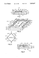
- FIG. 1 is a cross-sectional view of one embodiment of an accelerometer according to the present invention.
- FIG. 2 is a partially cut away perspective internal view of the embodiment of an accelerometer according to the present invention.
- FIG. 3 is a schematic diagram showing the placement of piezoresistive elements in one embodiment of an accelerometer according to the present invention.
- FIG. 4 is a graph showing electrostatic attraction vs. applied voltage with device sensitivity as a parameter to demonstrate the device insensitivity of the present invention.
- FIG. 5 is a graph showing electrostatic attraction vs. applied voltage with temperature as a parameter to demonstrate the temperature insensitivity of the present invention.
- FIG. 6 is a schematic representation of one embodiment of a ratiometric compensation sub-system according to the present invention.
- FIG. 7 cross-sectional view of a single beam accelerometer according to the present invention.
- the present invention comprises a three layer silicon-silicon-silicon structure having a doubly-supported mass and frame sandwiched between a silicon cap and a silicon base.
- a simplified cross-sectional view is presented in FIG. 1.
- FIG. 1 shows an accelerometer 100 comprising a silicon mass 110 suspended in a double support system including flexures 112 and 114 connected to a silicon frame 120.
- Frame 120 moves in response to external forces while mass 110 remains relatively still and thereby serve as the detector for the measurement of the forces.
- Flexures 112 and 114 include piezoresistors 130 and 132 which detect and measure the relative movements of mass 110.
- Mass 110 is constructed in a way so as to be conducting, either itself being a conductor or having one or more conducting plates attached to it.
- Atop frame 120 is a silicon cap 140 having a cut-away portion to provide an air gap 142.
- a deflection electrode 160 Disposed along the cut-away portion on cap 140 is a deflection electrode 160 which, in conjunction with mass 110, produces a potential difference between deflection electrode 160 and mass 110.
- Below frame 120 is silicon base 150 which provides support to frame 120.
- mass 110 is preferably shaped such that it does not touch base 150, leaving a second air gap 152 between frame 120 and base 150 when mass 110 is in an undeflected state. Bond pads, exemplified by pad 161, enable external electrical connection to accelerometer 100.
- air gaps 142 and 152 allow mass 110 to move within accelerometer 100 and also provide squeeze film damping for mass 110 when it moves.
- Squeeze film damping is a phenomenon wherein air being squeezed between two large area plates resists the movement of the plates. The limited sizes of their gaps allow cap 140 and base 150 to serve as mechanical stops to the motion of mass 110, thereby preventing excess movement of mass 110 which may destroy the device.
- squeeze film damping and mechanical stops also control resonance oscillations which are common in accelerometers. Resonance amplification factors in excess of 30,000 for silicon spring mass systems have been observed when there is no damping.
- cap 140 and base 150 provide squeeze film damping using air and mechanical stops to control both overforce and resonance oscillations.
- Cap 140 and base 150 may be made of the same material as mass 110 and frame 120, so fabrication may be simplified and temperature dependent stress transduction is minimized.
- Cap 140 and base 150 also provide seals against undesirable particulate matter entering accelerometer 100 and jamming the motions of mass 110.
- cap 140 and base 150 do not inadvertently impose an undesirable electrostatic force on mass 110.
- Both cap 140 and base 150 are usually electrically isolated from the sensing element. However, cap 140 and base 150 may each float to some arbitrary voltage due to extraneous electrical interactions caused by, for example, incident light, adjacent wiring, and even moisture. Base 150 is therefore preferably grounded.
- electrode 160 is preferably disposed between cap 140 and mass 110, it acts as an electrostatic field shield for mass 110 to shield it from the effects of any voltage on cap 140.
- FIG. 2 presents a perspective view of the preferred embodiment of the present invention.
- Accelerometer 200 is shown with cap 240 partially cut away to reveal the suspension of mass 210 on frame 220 which is disposed on base 250.
- Mass 210 and its flexures 212-215 comprise a diaphragm 270 which moves relative to frame 220 in response to applied accelerations.
- Flexures 212-215 are disposed at the top surface of mass 210.
- the center of mass of mass 210 is somewhere near its middle below the surface thereof. This produces a movement of mass 210 when it is subjected to a cross-axis acceleration. Sensitivity of an accelerometer to this off-axis acceleration is in many cases undesirable.
- the electrical response to these off-axis movements can be significantly reduced by a connection of the piezoresistive elements in a Wheatstone Bridge as shown in FIG. 3.
- FIG. 3 is a schematic of an embodiment of the present invention having eight piezoresistors connected in a Wheatstone Bridge configuration 311 with two sensing resistors in each leg of the Bridge. Two resistors are in each flexure, one at the mass end of the flexure and one at the frame end of the flexure.
- "m” and "f” represents whether the piezoresistor is one positioned at the mass end or the frame end of the flexure, respectively.
- 312m and 312f are sensor resistors on flexure 212 (of FIG. 2) which are proximate the mass and frame respectively.
- the other sensor resistor pairs, 313m/313f, 314m/314f, and 315m/315f are similarly attached to flexures 213, 214, and 215 of FIG. 2. If the piezoresistive elements are well-matched and the movement of the mass is about its center of mass, then the equal and opposite responses from these piezoresistive elements make it theoretically possible to obtain output from the accelerometer for accelerations in the vertical (or principal axis) direction only. In practice, this implementation achieves a less than 1% response to off-axis accelerations and the elimination of observable off-axis resonances. For details of this theory, see H. Sandmaier, et al., "A silicon based micromechanical accelerometer with cross acceleration sensitivity compensation", Transducers '87 Digest of Technical Papers, June 1987, p. 399.
- a metal conductor 180 is formed from the surface of cap 240 onto the top of frame 220 in a conventional manner such that electrical conduction is established between one of the bonding pads 161 and electrode 160. All the bonding pads then are on the top surface of frame 220.
- the air gap 132 between electrode 160 and the upper surface of mass 110 can also be tailored to better than 2% by controlling the depth of the etch of cap 240.
- mass 110 is 3.6 mm square and accelerometer 100 is 7.7 ⁇ 7.2 ⁇ 1.2 mm.
- one or more electrodes are disposed in cap 240.
- electrostatic forces generated thereby can cause a deflection of mass 110.
- This system thus provides a primary test of accelerometer 100: if a potential difference is applied sufficient to produce a deflection and mass 110 moves in response to this controlled electrostatic force, then displacement can be detected by measurement of the change in output voltage of the Wheatstone Bridge 311, and thus the operational status of mass 110 is confirmed and accelerometer 100 shown to be operable.
- accelerometer 100 may be calibrated and ratiometrically compensated.
- the accelerometer's operation is based on fairly simple deflection equations.
- the sum of all forces acting on the mass 110 is zero:
- mg is the gravitational or acceleration force (acceleration in g)
- V is the applied voltage between the electrodes
- A is the electrode area
- e is the dielectric constant of the damping media.
- the displacement is proportional to acceleration with the proportionality constant being m/k s . Because the piezoresistors respond to stress in the springs by varying the output voltage of the Wheatstone bridge and stress and strain are directly related by Young's Modulus, then the displacement can be derived by measuring the change in output voltage of the Wheatstone Bridge. If an electrostatic force is applied, equation (1) becomes non-linear: ##EQU1##
- ⁇ x can be neglected compared with x o .
- the deflection is in the range of 3%. Note that for very sensitive devices (for instance, 5 g full-scale parts), the deflection can be made fairly large and therefore some adjustment of the electrostatic voltage compared to the full scale range needs to be made to optimize predictability of the response.
- the present invention thus possesses the advantage of enabling acceleration measurements which do not significantly depend upon a particular device's sensitivity or ambient temperature variations. That is, the flexures (as measured by spring constants) of the piezoresistive supports may vary from device to device (producing device sensitivity variations at least as high as 3 to 1) and the temperature environment may change by as much as 110° C., as long as the initial gap distance between a electrode and the mass is held constant, a given applied electrostatic voltage will produce substantially the same electrostatic attraction.
- the spring constant is relatively large, producing relatively small deflections for a given applied force.
- the deformable member of the present invention is relatively stiff. For example, for a 1.
- the mass is 0.99 mg.
- the springs are 320 ⁇ m long by 70 ⁇ m wide by 7 ⁇ m thick. These dimensions yield a spring constant of 730 kg/m 2 and a peak strain in the supports of 160 ⁇ strains for 50 g.
- the deflection of the mass for a 50 g acceleration is approximately 0.7 ⁇ m.
- there are closed-loop inertial type systems which allow deflection of the mass, but these typically levitate the mass in an electric or magnetic force field and thus require a relatively low spring constant for operation.
- FIG. 4 is a graph of electrostatic attraction in units of g versus applied electode voltage in volts with sensitivity (S) as a parameter. As can be seen, variations in sensitivity of 0.79 to 2.18 mv/g all give approximately the same electrostatic acceleration values as a function of applied electrode voltage.
- accelerometers according to the present invention may be tested at the wafer level by exciting each device on the wafer with a step in the deflection voltage and measuring the sensitivity.
- This feature of the present invention greatly improves testing efficiency because accelerometers need not be individually mounted in a test gig before testing can be performed, as is necessary in the prior art.
- FIG. 5 shows that electrostatic acceleration as a function of electrode voltage is also not significantly dependent upon operating temperatures, which, in this test, was varied from -25° C. to 100° C. representing a change in piezoresistive sensitivity of approximately 25%). This shows that self-testing according to the present invention in situ where there may be extreme variations of temperature as, for instance, in geophysical applications, is a practical application.
- the self-testable accelerometer according to the present invention is highly desirable in that it allows automatic or manual calibration and recalibration of the accelerometer in situ.
- a computer recomputes the accelerometer sensitivity in a periodic fashion, the advantage is that the effects of long term changes in sensitivity are eliminated and the system can thus utilize sensors having temperature dependent sensitivities which do not approximate simple straight lines.
- the present invention also provides a method of testing the damping characteristic over frequency.
- the stiffness of the spring constant of the diaphragm, the squeeze film damping and the mechanical stops provided by the caps damp the movements of the mass on the diaphragm. If a potential difference is applied between the mass and the capacitive plate to produce movement of the mass at a predetermined frequency, then by measuring the degree of movement of over time the damping characteristic may be determined. This procedure may be repeated at many different frequencies to determine the damping characteristic for each frequency.
- this type of testing may be done at the wafer level of fabrication, thereby providing a diagnostic test at an early stage to save time, effort, and cost.
- the present invention may be ratiometrically sensitivity-compensated either manually or automatically by computer to produce a continuously corrected output.
- a preferred embodiment of a circuit 600 for this purpose is shown in FIG. 6.
- a sensor 610 comprises four piezoresistive elements 601-604 in a Wheatstone Bridge configuration 630 mounted on a deflectable mass (not shown) and having a deflection electrode 620 adjacent thereto. Electrode 620 is connected in parallel with 610 so that a potential difference may be established between electrode 620 and the mass. Nodes C and D of Wheatstone Bridge 630 are coupled to inputs of a differential amplifier 640. The output of amplifier 640 is coupled to a plurality of switches S1, S2, and S3. Although any conventional switch means can be used for the switching function according to the present invention, shown in FIG. 6 is an implementation using field effect transistors (FETs) as the preferred switches.
- FETs field effect transistors
- Switches electronically couple the signal from sensor 610 to one of three sample and hold devices, shown as capacitors 618, 622 and 624, respectively.
- Sample and hold devices 622 and 624 feed opposite inputs of a differential amplifier 660, whose feeds a fourth sample and hold device, shown as capacitor 619, through a fourth switch S4.
- the output of sample and hold device 619 feeds the reference input of ratiometric A/D converter 650 and the output of sample and hold device 618 feeds the signal input of A/D converter 650.
- a switch S5 controls the generation of an electrostatic force by electrode 620.
- a calibrate signal preferably generated by a computer or other accelerometer processor, or the like, generates a pulse which closes switches S2, S4 and S5 and opens switches S1 and S3.
- switch S5 acts to cause the sensor output to be a multiplexed combination of the normal accelerometer sensor output and the signal change resulting from the electrostatic force generated by electrode 620.
- This multiplexed signal is amplified by amplifier 640 and fed to sample and hold device 622.
- Amplifier 660 acts to extract the calibration signal on a real time basis from the signal output by amplifier 640 in the following manner.
- switch S2 is opened and switches S3 and S1 are closed. Since S5 is now also open, the signal output from amplifier 640 is the normal sensor signal without the addition of the calibrate signal.
- This signal is fed through switch S1 to sample and hold device 618 for feeding to the A/D converter 650 as the normal signal from the accelerometer.
- the normal signal is also fed through switch S3 to the other sample and hold device 624 feeding amplifier 660.
- the one input to amplifier 660 from sample and hold device 622 is the normal sensor signal plus the calibration signal whereas the other input to amplifier 660 is the signal without the calibration signal.
- amplifier 660 is a differential amplifier, the output thereof is thus the difference between the two signals retained on sample and hold devices 622 and 624 respectively, and thus constitutes the calibration signal demultiplexed from the normal accelerometer signal. During the next appearance of a calibrate signal, with switch S4 closed, the output of amplifier 660 is fed to sample and hold device 619 for input as the reference signal to the A/D converter 650.
- the signal output on the digital output lines of A/D converter 650 is normalized to the electrostatic force applied sensor 610 and is independent of temperature and other drift terms.
- an analog division of the signal to the reference is achieved.
- a division of the signal output to the calibration output is obtained.
- the ratiometric division will then normalize the sensor's output based on the calibration. If an analog output were desired from the ratiometric self-testable circuit 600, one would merely add a digital to analog (D/A) converter on the output of A/D converter 650. Note that the sample and hold approach used in circuit 600 may be simplified in a manner conventional in the art.
- FIG. 7 Another embodiment of the present invention is a single beam (also referred to as a single cantilever) accelerometer 700 as shown in cross-section in FIG. 7.
- a mass 710 is attached by support flexure 712 to a frame 720 and a least one piezoresistive element is attached to flexure 71 to sense movements of mass 710.
- a cap 740 overlies mass 710 and frame 720 with deflection electrode 760 disposed opposite mass 710.
- air gaps 742 and 752 are preferably formed about mass 710 to provide squeeze film damping of movements of mass 710.
- Cap 740 and base 750 are further designed to provide appropriate mechanical stops for the motion of mass 710.
- accelerometer 700 may be tested and calibrated at the wafer level and in situ having all the features and advantages of the diaphragm accelerometer of FIG. 1.
- the tip of mass 710 will tend to deflect upwards, and since there is no Wheatstone Bridge balancing of piezoresistance in a single beam device, there will be no off-axis cancellation.
- This off-axis acceleration can be reduced somewhat by mounting the die during fabrication such that the center of flexure 712 and the center of mass 710 are co-planar.
- the mounting angle is 3° to 8° from flat.
- Another embodiment of the present invention comprises a plurality of electrodes disposed so as to pull the mass towards one corner, along a side, or towards any direction by a combination of electrostatic forces generated by the plurality of electrodes. Any combination of electrostatic forces generated by configurations of electrodes is deemed be within the scope of the present invention.
- a particular example is a placement of an electrode on the base (150 in FIG. 1) of the accelerometer below the mass so that an electrostatic force thereby generated would operate in conjunction with an electrode on the cap to produce a push-pull action of the mass. This would be useful, for example, in applications having larger displacements of the mass to achieve increased accuracy of measurement.
- Equation (3) large values of x causes the relationship to be non-linear
- Equation (4) for the acceleration then becomes: ##EQU3##
- Another embodiment of the present invention is an angular accelerometer structure wherein a non-uniform electrostatic force is utilized to pull up on one side of the mass and not the other side thereby producing an angular motion of the mass. This would be useful in angular acceleration applications because the electrostatic force can be made constant and thus simulate a constant angular acceleration without having to spin the device.
Abstract
Description
0=9.8 mg-F.sub.electro -K.sub.s (X.sub.o -X) (1)
F.sub.electro =0.5πeA(V/X).sup.2 (2)
Claims (13)
Priority Applications (3)
| Application Number | Priority Date | Filing Date | Title |
|---|---|---|---|
| US07/370,364 US5103667A (en) | 1989-06-22 | 1989-06-22 | Self-testable micro-accelerometer and method |
| US07/915,792 US5253510A (en) | 1989-06-22 | 1992-07-17 | Self-testable micro-accelerometer |
| US08/138,349 US5445006A (en) | 1989-06-22 | 1993-10-18 | Self-testable micro-accelerometer and method |
Applications Claiming Priority (1)
| Application Number | Priority Date | Filing Date | Title |
|---|---|---|---|
| US07/370,364 US5103667A (en) | 1989-06-22 | 1989-06-22 | Self-testable micro-accelerometer and method |
Related Child Applications (1)
| Application Number | Title | Priority Date | Filing Date |
|---|---|---|---|
| US66818091A Division | 1989-06-22 | 1991-03-12 |
Publications (1)
| Publication Number | Publication Date |
|---|---|
| US5103667A true US5103667A (en) | 1992-04-14 |
Family
ID=23459312
Family Applications (1)
| Application Number | Title | Priority Date | Filing Date |
|---|---|---|---|
| US07/370,364 Expired - Fee Related US5103667A (en) | 1989-06-22 | 1989-06-22 | Self-testable micro-accelerometer and method |
Country Status (1)
| Country | Link |
|---|---|
| US (1) | US5103667A (en) |
Cited By (52)
| Publication number | Priority date | Publication date | Assignee | Title |
|---|---|---|---|---|
| US5241850A (en) * | 1991-11-01 | 1993-09-07 | Texas Instruments Incorporated | Sensor with programmable temperature compensation |
| DE4316263A1 (en) * | 1992-05-19 | 1993-11-25 | Hitachi Ltd | Acceleration sensor self-test appts. for diagnosing vehicle airbag system - applies force by electrostatic, electromagnetic force, or external mechanical vibration, and measures detected acceleration of mass |
| DE4226224A1 (en) * | 1992-08-07 | 1994-02-10 | Texas Instruments Deutschland | Monocrystalline silicon@ force sensor - connects central deformable section to outer base by carriers which support piezo-resistances, and has meandering tortuous path conductive tracks on deformable section for passage of test current |
| US5295386A (en) * | 1989-12-28 | 1994-03-22 | Kazuhiro Okada | Apparatus for detecting acceleration and method for testing this apparatus |
| US5305629A (en) * | 1992-11-06 | 1994-04-26 | Automotive Systems Laboratory, Inc. | Regulated negative calibration pulse generator |
| US5337260A (en) * | 1993-07-12 | 1994-08-09 | Ford Motor Company | Method for calibrating a single point impact sensor |
| US5343731A (en) * | 1991-10-02 | 1994-09-06 | Nec Corporation | Semiconductor accelerometer |
| DE4419267A1 (en) * | 1993-06-03 | 1994-12-15 | Fuji Electric Co Ltd | Semiconductor acceleration sensor and test method therefor |
| US5387819A (en) * | 1991-03-20 | 1995-02-07 | Hitachi, Ltd. | Crash detection apparatus of air bag system |
| US5391283A (en) * | 1989-10-20 | 1995-02-21 | Hitachi, Ltd. | Detector having self-calibration function |
| WO1995005608A1 (en) * | 1993-08-18 | 1995-02-23 | Automotive Systems Laboratory, Inc. | Interface circuit for compensation of sensor output variations |
| US5415044A (en) * | 1993-01-14 | 1995-05-16 | Mitsubishi Denki Kabushiki Kaisha | Semiconductor acceleration sensor including means for detecting weight detachment |
| US5433101A (en) * | 1993-07-12 | 1995-07-18 | Ford Motor Company | Method and apparatus for self-testing a single-point automotive impact sensing system |
| US5445006A (en) * | 1989-06-22 | 1995-08-29 | Ic Sensors, Inc. | Self-testable micro-accelerometer and method |
| WO1995027216A1 (en) * | 1994-03-30 | 1995-10-12 | Siemens Aktiengesellschaft | Micromechanical sensor unit for detecting acceleration |
| US5465604A (en) * | 1990-08-17 | 1995-11-14 | Analog Devices, Inc. | Method for adjusting sensitivity of a sensor |
| US5490421A (en) * | 1992-03-25 | 1996-02-13 | Fuji Electric Co., Ltd. | Semi-conductor acceleration sensor having thin beam supported weight |
| US5492020A (en) * | 1991-03-30 | 1996-02-20 | Okada; Kazuhiro | Detector for a physical quantity having a self-testing function |
| US5506454A (en) * | 1991-03-20 | 1996-04-09 | Hitachi, Ltd. | System and method for diagnosing characteristics of acceleration sensor |
| US5528520A (en) * | 1994-12-08 | 1996-06-18 | Ford Motor Company | Calibration circuit for capacitive sensors |
| GB2266151B (en) * | 1992-03-25 | 1996-09-11 | Fuji Electric Co Ltd | Semiconductor acceleration sensor |
| US5583290A (en) * | 1994-12-20 | 1996-12-10 | Analog Devices, Inc. | Micromechanical apparatus with limited actuation bandwidth |
| US5620931A (en) * | 1990-08-17 | 1997-04-15 | Analog Devices, Inc. | Methods for fabricating monolithic device containing circuitry and suspended microstructure |
| US5659195A (en) * | 1995-06-08 | 1997-08-19 | The Regents Of The University Of California | CMOS integrated microsensor with a precision measurement circuit |
| US5698770A (en) * | 1996-06-06 | 1997-12-16 | Trw Inc. | Method and apparatus for trimming gain of an accelerometer |
| US5710376A (en) * | 1995-12-22 | 1998-01-20 | International Business Machines Corporation | Charged mass thin film condenser accelerometer |
| US5737961A (en) * | 1996-03-26 | 1998-04-14 | Trw Inc. | Method and apparatus for detecting operational failure of a digital accelerometer |
| US5753793A (en) * | 1993-08-24 | 1998-05-19 | A/S Bruel & Kjaer | Apparatus for detecting the malfunctioning of an accelerometer |
| US5760290A (en) * | 1994-10-21 | 1998-06-02 | Fuji Electric Co., Ltd. | Semiconductor acceleration sensor and testing method thereof |
| US5827967A (en) * | 1995-05-23 | 1998-10-27 | Fuji Electric Co., Ltd. | Semiconductor accelerometer including strain gauges forming a wheatstone bridge and diffusion resistors |
| US5847280A (en) * | 1990-08-17 | 1998-12-08 | Analog Devices, Inc. | Monolithic micromechanical apparatus with suspended microstructure |
| US5900529A (en) * | 1997-07-10 | 1999-05-04 | Trw Inc. | Apparatus and method for testing an acceleration sensor |
| US6170332B1 (en) | 1993-05-26 | 2001-01-09 | Cornell Research Foundation, Inc. | Micromechanical accelerometer for automotive applications |
| US6564637B1 (en) | 1998-10-01 | 2003-05-20 | Eads Deutschland Gmbh | Sensor having a resonance structure, especially an acceleration or rotation rate sensor, and a device for carrying out a self-test |
| US20040200281A1 (en) * | 2003-04-11 | 2004-10-14 | Kenny Thomas W. | Ultra-miniature accelerometers |
| US6864677B1 (en) | 1993-12-15 | 2005-03-08 | Kazuhiro Okada | Method of testing a sensor |
| US6871413B1 (en) * | 1997-12-15 | 2005-03-29 | Microstrain, Inc. | Miniaturized inclinometer for angle measurement with accurate measurement indicator |
| EP1612531A2 (en) * | 2004-06-23 | 2006-01-04 | EADS Deutschland GmbH | Micro- mechanical structure |
| US20060005603A1 (en) * | 2004-07-08 | 2006-01-12 | Chau Kevin H | Method for calibrating accelerometer sensitivity |
| FR2872900A1 (en) * | 2004-07-09 | 2006-01-13 | Commissariat Energie Atomique | METHOD FOR TESTING A VARIABLE CAPACITY MEASUREMENT SYSTEM |
| US20060061372A1 (en) * | 2004-09-17 | 2006-03-23 | Denso Corporation | Capacitive physical quantity sensor |
| US20070062286A1 (en) * | 2005-09-16 | 2007-03-22 | Vti Technologies Oy | Method for the micromechanical measurement of acceleration and a micromechanical acceleration sensor |
| US20080028823A1 (en) * | 2006-08-01 | 2008-02-07 | Howard Samuels | Sensor Self-Test Transfer Standard |
| DE10046958B4 (en) * | 1999-09-27 | 2009-01-02 | Denso Corp., Kariya-shi | Capacitive device for detecting a physical quantity |
| US20090280594A1 (en) * | 2006-05-10 | 2009-11-12 | Qualtre, Inc. | Three-axis accelerometers and fabrication methods |
| US7757393B2 (en) | 2005-06-03 | 2010-07-20 | Georgia Tech Research Corporation | Capacitive microaccelerometers and fabrication methods |
| DE102007016792B4 (en) * | 2007-04-05 | 2013-05-29 | Ifm Electronic Gmbh | sensor |
| JP2013164301A (en) * | 2012-02-09 | 2013-08-22 | Seiko Epson Corp | Electronic device, manufacturing method of the same and electronic apparatus |
| CN103582607A (en) * | 2011-06-30 | 2014-02-12 | 惠普发展公司,有限责任合伙企业 | Calibration of MEMS sensor |
| US20140096587A1 (en) * | 2012-10-08 | 2014-04-10 | Northrop Grumman Systems Corporation | Dynamic self-calibration of an accelerometer system |
| WO2014200606A2 (en) * | 2013-04-14 | 2014-12-18 | Purdue Research Foundation | Performance improvement of mems devices |
| CN110568223A (en) * | 2019-10-17 | 2019-12-13 | 上海三菱电梯有限公司 | motor magnetic encoder detection system |
Citations (4)
| Publication number | Priority date | Publication date | Assignee | Title |
|---|---|---|---|---|
| US2923904A (en) * | 1960-02-02 | Differential transformer accelerometer | ||
| US4071838A (en) * | 1976-02-09 | 1978-01-31 | Diax Corporation | Solid state force transducer and method of making same |
| US4891985A (en) * | 1985-07-22 | 1990-01-09 | Honeywell Inc. | Force sensor with attached mass |
| US4922756A (en) * | 1988-06-20 | 1990-05-08 | Triton Technologies, Inc. | Micro-machined accelerometer |
-
1989
- 1989-06-22 US US07/370,364 patent/US5103667A/en not_active Expired - Fee Related
Patent Citations (4)
| Publication number | Priority date | Publication date | Assignee | Title |
|---|---|---|---|---|
| US2923904A (en) * | 1960-02-02 | Differential transformer accelerometer | ||
| US4071838A (en) * | 1976-02-09 | 1978-01-31 | Diax Corporation | Solid state force transducer and method of making same |
| US4891985A (en) * | 1985-07-22 | 1990-01-09 | Honeywell Inc. | Force sensor with attached mass |
| US4922756A (en) * | 1988-06-20 | 1990-05-08 | Triton Technologies, Inc. | Micro-machined accelerometer |
Cited By (97)
| Publication number | Priority date | Publication date | Assignee | Title |
|---|---|---|---|---|
| US5445006A (en) * | 1989-06-22 | 1995-08-29 | Ic Sensors, Inc. | Self-testable micro-accelerometer and method |
| US5391283A (en) * | 1989-10-20 | 1995-02-21 | Hitachi, Ltd. | Detector having self-calibration function |
| US5574211A (en) * | 1989-10-20 | 1996-11-12 | Hitachi, Ltd. | Detector having self-calibration function |
| US5429736A (en) * | 1989-10-20 | 1995-07-04 | Hitachi, Ltd. | Detector having self-calibration function |
| US20050199434A1 (en) * | 1989-12-28 | 2005-09-15 | Kazuhiro Okada | Apparatus for detecting a physical quantity acting as an external force and method for testing and manufacturing the apparatus |
| US5295386A (en) * | 1989-12-28 | 1994-03-22 | Kazuhiro Okada | Apparatus for detecting acceleration and method for testing this apparatus |
| US7231802B2 (en) | 1989-12-28 | 2007-06-19 | Kazuhiro Okada | Apparatus for detecting a physical quantity acting as an external force and method for testing and manufacturing the apparatus |
| US6185814B1 (en) | 1989-12-28 | 2001-02-13 | Kazuhiro Okada | Method of manufacturing a sensor detecting a physical action as an applied force |
| US20070256469A1 (en) * | 1989-12-28 | 2007-11-08 | Kazuhiro Okada | Apparatus for detecting a physical quantity acting as an external force and method for testing and manufacturing this apparatus |
| US6894482B2 (en) | 1989-12-28 | 2005-05-17 | Kazuhiro Okada | Apparatus for detecting a physical quantity acting as an external force and method for testing and manufacturing this apparatus |
| US6474133B1 (en) * | 1989-12-28 | 2002-11-05 | Kazuhiro Okada | Apparatus for detecting a physical quantity acting as an external force and method for testing and manufacturing this apparatus |
| US7578162B2 (en) | 1989-12-28 | 2009-08-25 | Kazuhiro Okada | Apparatus for detecting a physical quantity acting as an external force and method for testing and manufacturing this apparatus |
| US6512364B1 (en) | 1989-12-28 | 2003-01-28 | Kazuhiro Okada | Testing sensor |
| US5620931A (en) * | 1990-08-17 | 1997-04-15 | Analog Devices, Inc. | Methods for fabricating monolithic device containing circuitry and suspended microstructure |
| US5465604A (en) * | 1990-08-17 | 1995-11-14 | Analog Devices, Inc. | Method for adjusting sensitivity of a sensor |
| US6192757B1 (en) | 1990-08-17 | 2001-02-27 | Analog Devices, Inc. | Monolithic micromechanical apparatus with suspended microstructure |
| US5847280A (en) * | 1990-08-17 | 1998-12-08 | Analog Devices, Inc. | Monolithic micromechanical apparatus with suspended microstructure |
| US6009753A (en) * | 1990-08-17 | 2000-01-04 | Analog Devices, Inc. | Monolithic micromechanical apparatus with suspended microstructure |
| US5506454A (en) * | 1991-03-20 | 1996-04-09 | Hitachi, Ltd. | System and method for diagnosing characteristics of acceleration sensor |
| US5387819A (en) * | 1991-03-20 | 1995-02-07 | Hitachi, Ltd. | Crash detection apparatus of air bag system |
| US5492020A (en) * | 1991-03-30 | 1996-02-20 | Okada; Kazuhiro | Detector for a physical quantity having a self-testing function |
| US5343731A (en) * | 1991-10-02 | 1994-09-06 | Nec Corporation | Semiconductor accelerometer |
| US5241850A (en) * | 1991-11-01 | 1993-09-07 | Texas Instruments Incorporated | Sensor with programmable temperature compensation |
| US5490421A (en) * | 1992-03-25 | 1996-02-13 | Fuji Electric Co., Ltd. | Semi-conductor acceleration sensor having thin beam supported weight |
| GB2266151B (en) * | 1992-03-25 | 1996-09-11 | Fuji Electric Co Ltd | Semiconductor acceleration sensor |
| DE4316263A1 (en) * | 1992-05-19 | 1993-11-25 | Hitachi Ltd | Acceleration sensor self-test appts. for diagnosing vehicle airbag system - applies force by electrostatic, electromagnetic force, or external mechanical vibration, and measures detected acceleration of mass |
| DE4316263C2 (en) * | 1992-05-19 | 1998-10-22 | Hitachi Ltd | System and method for diagnosing characteristics of an acceleration sensor |
| DE4226224A1 (en) * | 1992-08-07 | 1994-02-10 | Texas Instruments Deutschland | Monocrystalline silicon@ force sensor - connects central deformable section to outer base by carriers which support piezo-resistances, and has meandering tortuous path conductive tracks on deformable section for passage of test current |
| GB2278687B (en) * | 1992-11-06 | 1996-06-26 | Automotive Systems Lab | Regulated negative calibration pulse generator |
| WO1994011742A1 (en) * | 1992-11-06 | 1994-05-26 | Automotive Systems Laboratory, Inc. | Regulated negative calibration pulse generator |
| US5305629A (en) * | 1992-11-06 | 1994-04-26 | Automotive Systems Laboratory, Inc. | Regulated negative calibration pulse generator |
| GB2278687A (en) * | 1992-11-06 | 1994-12-07 | Automotive Systems Lab | Regulated negative calibration pulse generator |
| US5415044A (en) * | 1993-01-14 | 1995-05-16 | Mitsubishi Denki Kabushiki Kaisha | Semiconductor acceleration sensor including means for detecting weight detachment |
| US6170332B1 (en) | 1993-05-26 | 2001-01-09 | Cornell Research Foundation, Inc. | Micromechanical accelerometer for automotive applications |
| US6199874B1 (en) | 1993-05-26 | 2001-03-13 | Cornell Research Foundation Inc. | Microelectromechanical accelerometer for automotive applications |
| DE4419267A1 (en) * | 1993-06-03 | 1994-12-15 | Fuji Electric Co Ltd | Semiconductor acceleration sensor and test method therefor |
| US5608153A (en) * | 1993-06-03 | 1997-03-04 | Fuji Electric Co., Ltd. | Semiconductor acceleration sensor and testing method thereof |
| DE4419267C2 (en) * | 1993-06-03 | 2003-02-27 | Fuji Electric Co Ltd | Semiconductor acceleration sensor and test method therefor |
| US5526687A (en) * | 1993-06-03 | 1996-06-18 | Fuji Electric Co., Ltd. | Semiconductor acceleration sensor and testing method thereof |
| US5337260A (en) * | 1993-07-12 | 1994-08-09 | Ford Motor Company | Method for calibrating a single point impact sensor |
| US5433101A (en) * | 1993-07-12 | 1995-07-18 | Ford Motor Company | Method and apparatus for self-testing a single-point automotive impact sensing system |
| WO1995005608A1 (en) * | 1993-08-18 | 1995-02-23 | Automotive Systems Laboratory, Inc. | Interface circuit for compensation of sensor output variations |
| US5753793A (en) * | 1993-08-24 | 1998-05-19 | A/S Bruel & Kjaer | Apparatus for detecting the malfunctioning of an accelerometer |
| US6864677B1 (en) | 1993-12-15 | 2005-03-08 | Kazuhiro Okada | Method of testing a sensor |
| WO1995027216A1 (en) * | 1994-03-30 | 1995-10-12 | Siemens Aktiengesellschaft | Micromechanical sensor unit for detecting acceleration |
| US5821419A (en) * | 1994-03-30 | 1998-10-13 | Siemens Aktiengesellschaft | Micromechanical sensor unit for detecting acceleration |
| US5987921A (en) * | 1994-10-21 | 1999-11-23 | Fuji Electric Co., Ltd | Method for making a semiconductor acceleration sensor |
| DE19539178B4 (en) * | 1994-10-21 | 2005-12-15 | Fuji Electric Co., Ltd., Kawasaki | Semiconductor acceleration sensor and method for its manufacture |
| US5760290A (en) * | 1994-10-21 | 1998-06-02 | Fuji Electric Co., Ltd. | Semiconductor acceleration sensor and testing method thereof |
| US5528520A (en) * | 1994-12-08 | 1996-06-18 | Ford Motor Company | Calibration circuit for capacitive sensors |
| US5583290A (en) * | 1994-12-20 | 1996-12-10 | Analog Devices, Inc. | Micromechanical apparatus with limited actuation bandwidth |
| DE19620459B4 (en) * | 1995-05-23 | 2004-09-23 | Fuji Electric Co., Ltd., Kawasaki | Semiconductor accelerometer and method for evaluating the properties of a semiconductor accelerometer |
| US5827967A (en) * | 1995-05-23 | 1998-10-27 | Fuji Electric Co., Ltd. | Semiconductor accelerometer including strain gauges forming a wheatstone bridge and diffusion resistors |
| US5659195A (en) * | 1995-06-08 | 1997-08-19 | The Regents Of The University Of California | CMOS integrated microsensor with a precision measurement circuit |
| US5710376A (en) * | 1995-12-22 | 1998-01-20 | International Business Machines Corporation | Charged mass thin film condenser accelerometer |
| US5737961A (en) * | 1996-03-26 | 1998-04-14 | Trw Inc. | Method and apparatus for detecting operational failure of a digital accelerometer |
| US5698770A (en) * | 1996-06-06 | 1997-12-16 | Trw Inc. | Method and apparatus for trimming gain of an accelerometer |
| US5900529A (en) * | 1997-07-10 | 1999-05-04 | Trw Inc. | Apparatus and method for testing an acceleration sensor |
| US6871413B1 (en) * | 1997-12-15 | 2005-03-29 | Microstrain, Inc. | Miniaturized inclinometer for angle measurement with accurate measurement indicator |
| US6564637B1 (en) | 1998-10-01 | 2003-05-20 | Eads Deutschland Gmbh | Sensor having a resonance structure, especially an acceleration or rotation rate sensor, and a device for carrying out a self-test |
| DE19845185B4 (en) * | 1998-10-01 | 2005-05-04 | Eads Deutschland Gmbh | Sensor with resonant structure and device and method for self-test of such a sensor |
| DE10046958B4 (en) * | 1999-09-27 | 2009-01-02 | Denso Corp., Kariya-shi | Capacitive device for detecting a physical quantity |
| US20040200281A1 (en) * | 2003-04-11 | 2004-10-14 | Kenny Thomas W. | Ultra-miniature accelerometers |
| US7104130B2 (en) * | 2003-04-11 | 2006-09-12 | The Board Of Trustees Of The Leland Stanford Junior University | Ultra-miniature accelerometers |
| EP1612531A2 (en) * | 2004-06-23 | 2006-01-04 | EADS Deutschland GmbH | Micro- mechanical structure |
| EP1612531A3 (en) * | 2004-06-23 | 2007-01-24 | EADS Deutschland GmbH | Micro- mechanical structure |
| US20060005603A1 (en) * | 2004-07-08 | 2006-01-12 | Chau Kevin H | Method for calibrating accelerometer sensitivity |
| US7093478B2 (en) | 2004-07-08 | 2006-08-22 | Analog Devices, Inc. | Method for calibrating accelerometer sensitivity |
| WO2006008417A1 (en) * | 2004-07-09 | 2006-01-26 | Commissariat A L'energie Atomique | Test method for a variable capacitance measuring system |
| US20090167320A1 (en) * | 2004-07-09 | 2009-07-02 | Commissariat A L'energie Atomique | Test method for a variable capacitance measuring system |
| FR2872900A1 (en) * | 2004-07-09 | 2006-01-13 | Commissariat Energie Atomique | METHOD FOR TESTING A VARIABLE CAPACITY MEASUREMENT SYSTEM |
| US7728603B2 (en) | 2004-07-09 | 2010-06-01 | Commissariat A L'energie Atomique | Test method for a variable capacitance measuring system |
| US7109727B2 (en) * | 2004-09-17 | 2006-09-19 | Denso Corporation | Capacitive physical quantity sensor |
| US20060061372A1 (en) * | 2004-09-17 | 2006-03-23 | Denso Corporation | Capacitive physical quantity sensor |
| US7757393B2 (en) | 2005-06-03 | 2010-07-20 | Georgia Tech Research Corporation | Capacitive microaccelerometers and fabrication methods |
| US7516038B2 (en) | 2005-09-16 | 2009-04-07 | Vti Technologies Oy | Method for the mircomechanical measurement of acceleration and a micromechanical acceleration sensor |
| US20070062286A1 (en) * | 2005-09-16 | 2007-03-22 | Vti Technologies Oy | Method for the micromechanical measurement of acceleration and a micromechanical acceleration sensor |
| CN101278200B (en) * | 2005-09-16 | 2011-08-31 | Vti技术有限公司 | A method for the micromechanical measurement of acceleration and a micromechanical acceleration sensor |
| US7892876B2 (en) | 2006-05-10 | 2011-02-22 | Qualtre, Inc. | Three-axis accelerometers and fabrication methods |
| US8372677B2 (en) | 2006-05-10 | 2013-02-12 | Qualtre, Inc. | Three-axis accelerometers and fabrication methods |
| US20090280594A1 (en) * | 2006-05-10 | 2009-11-12 | Qualtre, Inc. | Three-axis accelerometers and fabrication methods |
| US8056389B2 (en) | 2006-08-01 | 2011-11-15 | Analog Devices, Inc. | Sensor self-test transfer standard |
| US20090235717A1 (en) * | 2006-08-01 | 2009-09-24 | Analog Devices, Inc. | Sensor Self-Test Transfer Standard |
| US7543473B2 (en) | 2006-08-01 | 2009-06-09 | Analog Devices, Inc. | Sensor self-test transfer standard |
| US20080028823A1 (en) * | 2006-08-01 | 2008-02-07 | Howard Samuels | Sensor Self-Test Transfer Standard |
| DE102007016792B4 (en) * | 2007-04-05 | 2013-05-29 | Ifm Electronic Gmbh | sensor |
| EP2726400A4 (en) * | 2011-06-30 | 2015-03-04 | Hewlett Packard Development Co | Calibration of mems sensor |
| CN103582607A (en) * | 2011-06-30 | 2014-02-12 | 惠普发展公司,有限责任合伙企业 | Calibration of MEMS sensor |
| US9403671B2 (en) | 2011-06-30 | 2016-08-02 | Hewlett-Packard Development Company, L.P. | Calibration of MEMS sensor |
| JP2013164301A (en) * | 2012-02-09 | 2013-08-22 | Seiko Epson Corp | Electronic device, manufacturing method of the same and electronic apparatus |
| US20140096587A1 (en) * | 2012-10-08 | 2014-04-10 | Northrop Grumman Systems Corporation | Dynamic self-calibration of an accelerometer system |
| US9702897B2 (en) * | 2012-10-08 | 2017-07-11 | Northrop Grumman Systems Corporation | Dynamic self-calibration of an accelerometer system |
| US10495664B2 (en) | 2012-10-08 | 2019-12-03 | Northrop Grumman Systems Corporation | Dynamic self-calibration of an accelerometer system |
| WO2014200606A2 (en) * | 2013-04-14 | 2014-12-18 | Purdue Research Foundation | Performance improvement of mems devices |
| WO2014200606A3 (en) * | 2013-04-14 | 2015-02-05 | Purdue Research Foundation | Performance improvement of mems devices |
| US10024879B2 (en) | 2013-04-14 | 2018-07-17 | Purdue Research Foundation | Performance improvement of MEMS devices |
| CN110568223A (en) * | 2019-10-17 | 2019-12-13 | 上海三菱电梯有限公司 | motor magnetic encoder detection system |
Similar Documents
| Publication | Publication Date | Title |
|---|---|---|
| US5103667A (en) | Self-testable micro-accelerometer and method | |
| US5253510A (en) | Self-testable micro-accelerometer | |
| Allen et al. | Accelerometer systems with self-testable features | |
| US5831164A (en) | Linear and rotational accelerometer | |
| US4941354A (en) | Tri-axial accelerometers | |
| US5465604A (en) | Method for adjusting sensitivity of a sensor | |
| US6496348B2 (en) | Method to force-balance capacitive transducers | |
| US6327909B1 (en) | Bistable mechanical sensors capable of threshold detection and automatic elimination of excessively high amplitude data | |
| US5481905A (en) | Transducer circuit having negative integral feedback | |
| AU644547B2 (en) | Self-calibrating accelerometer | |
| KR950000333B1 (en) | Accelerometer having means for preventing excessive deflection and production method | |
| US5009111A (en) | Differential force balance apparatus | |
| EP0691542A1 (en) | Improved accelerometers | |
| US3327270A (en) | Semi-conductor sensing assembly | |
| US5163325A (en) | Self-compensating accelerometer | |
| Payne et al. | Surface micromachined accelerometer: A technology update | |
| Alves et al. | High-resolution MEMS inclinometer based on pull-in voltage | |
| US4091680A (en) | Force transducer having a linear transfer characteristic | |
| US6109114A (en) | Caging, calibration, characterization and compensation of microstructural transducers | |
| Allen et al. | Self-testable accelerometer systems | |
| US5287724A (en) | Method for calibrating an accelerometer | |
| US20050066704A1 (en) | Method and device for the electrical zero balancing for a micromechanical component | |
| US20220144623A1 (en) | Micromechanical sensor element | |
| US3248936A (en) | Temperature compensated transducer | |
| US7434482B1 (en) | Feedback-controlled piezoelectric force measuring apparatus |
Legal Events
| Date | Code | Title | Description |
|---|---|---|---|
| AS | Assignment |
Owner name: IC SENSORS, 1710 MCCARTHY BOULEVARD, MILPITAS, CA Free format text: ASSIGNMENT OF ASSIGNORS INTEREST.;ASSIGNORS:ALLEN, HENRY V.;TERRY, STEPHEN C.;DE BRUIN, DIEDERIK W.;REEL/FRAME:005097/0837 Effective date: 19890620 |
|
| AS | Assignment |
Owner name: IC SENSORS, INC., A CORP. OF CA, CALIFORNIA Free format text: ASSIGNMENT OF ASSIGNORS INTEREST.;ASSIGNORS:ALLEN, HENRY V.;TERRRY, STEPHEN C.;DE BRUIN, DIEDERIK W.;REEL/FRAME:005818/0013 Effective date: 19910821 |
|
| CC | Certificate of correction | ||
| AS | Assignment |
Owner name: SILICON VALLEY BANK, CALIFORNIA Free format text: SECURITY INTEREST;ASSIGNOR:IC SENSORS, INC.;REEL/FRAME:007077/0910 Effective date: 19940317 |
|
| FEPP | Fee payment procedure |
Free format text: PAT HLDR NO LONGER CLAIMS SMALL ENT STAT AS SMALL BUSINESS (ORIGINAL EVENT CODE: LSM2); ENTITY STATUS OF PATENT OWNER: LARGE ENTITY Free format text: PAYOR NUMBER ASSIGNED (ORIGINAL EVENT CODE: ASPN); ENTITY STATUS OF PATENT OWNER: LARGE ENTITY |
|
| FPAY | Fee payment |
Year of fee payment: 4 |
|
| FPAY | Fee payment |
Year of fee payment: 8 |
|
| AS | Assignment |
Owner name: PNC BANK, NATIONAL ASSOCIATIONS, NEW JERSEY Free format text: SECURITY INTEREST;ASSIGNOR:IC SENSORS, INC;REEL/FRAME:011027/0792 Effective date: 20000215 |
|
| AS | Assignment |
Owner name: IC SENSORS, INC., CALIFORNIA Free format text: RELEASE BY SECURED PARTY;ASSIGNOR:SILICON VALLEY BANK;REEL/FRAME:010832/0438 Effective date: 19940317 |
|
| AS | Assignment |
Owner name: FIRST UNION NATIONAL BANK, AS AGENT, NEW JERSEY Free format text: SECURITY INTEREST;ASSIGNOR:IC SENSORS, INC.;REEL/FRAME:011284/0293 Effective date: 20000807 |
|
| AS | Assignment |
Owner name: FLEET CAPITAL CORPORATION, TEXAS Free format text: SECURITY AGREEMENT;ASSIGNORS:MEASUREMENT SPECIALTIES, INC.;IC SENSORS, INC.;REEL/FRAME:013845/0001 Effective date: 20030131 Owner name: IC SENSORS, INC., NEW JERSEY Free format text: RELEASE OF SECURITY INTEREST IN PATENTS AND TRADEM;ASSIGNOR:WACHOVIA BANK, NATIONAL ASSOCIATION;REEL/FRAME:013879/0721 Effective date: 20030130 Owner name: MEASUREMENTSPECIALTIES, INC., NEW JERSEY Free format text: RELEASE OF SECURITY INTEREST IN PATENTS AND TRADEM;ASSIGNOR:WACHOVIA BANK, NATIONAL ASSOCIATION;REEL/FRAME:013879/0721 Effective date: 20030130 |
|
| REMI | Maintenance fee reminder mailed | ||
| LAPS | Lapse for failure to pay maintenance fees | ||
| FP | Lapsed due to failure to pay maintenance fee |
Effective date: 20040414 |
|
| AS | Assignment |
Owner name: MEASUREMENT SPECIALTIES, INC., NEW JERSEY Free format text: RELEASE OF SECURITY INTEREST;ASSIGNOR:FLEET CAPITAL CORPORATION;REEL/FRAME:016824/0143 Effective date: 20041217 Owner name: IC SENSORS, INC., NEW JERSEY Free format text: RELEASE OF SECURITY INTEREST;ASSIGNOR:FLEET CAPITAL CORPORATION;REEL/FRAME:016824/0143 Effective date: 20041217 |
|
| AS | Assignment |
Owner name: MEASUREMENT SPECIALTIES, INC., NEW JERSEY Free format text: RELEASE BY SECURED PARTY;ASSIGNOR:FLEET CAPITAL CORPORATION;REEL/FRAME:016800/0587 Effective date: 20041217 Owner name: IC SENSORS, INC., NEW JERSEY Free format text: RELEASE BY SECURED PARTY;ASSIGNOR:FLEET CAPITAL CORPORATION;REEL/FRAME:016800/0587 Effective date: 20041217 |
|
| AS | Assignment |
Owner name: I C SENSORS INC., NEW JERSEY Free format text: RELEASE OF LIEN ON PATENTS;ASSIGNOR:PNC BANK NATIONAL ASSOCIATION;REEL/FRAME:026673/0060 Effective date: 20110721 |
|
| STCH | Information on status: patent discontinuation |
Free format text: PATENT EXPIRED DUE TO NONPAYMENT OF MAINTENANCE FEES UNDER 37 CFR 1.362 |