US5083591A - Process for dispensing liquid colorants into a paint can, and quality control therefor - Google Patents
Process for dispensing liquid colorants into a paint can, and quality control therefor Download PDFInfo
- Publication number
- US5083591A US5083591A US07/432,991 US43299189A US5083591A US 5083591 A US5083591 A US 5083591A US 43299189 A US43299189 A US 43299189A US 5083591 A US5083591 A US 5083591A
- Authority
- US
- United States
- Prior art keywords
- paint
- dispensing
- station
- base
- block
- Prior art date
- Legal status (The legal status is an assumption and is not a legal conclusion. Google has not performed a legal analysis and makes no representation as to the accuracy of the status listed.)
- Expired - Fee Related
Links
- 239000003973 paint Substances 0.000 title claims abstract description 236
- 239000003086 colorant Substances 0.000 title claims abstract description 126
- 239000007788 liquid Substances 0.000 title claims abstract description 80
- 238000000034 method Methods 0.000 title claims description 47
- 238000003908 quality control method Methods 0.000 title abstract description 28
- 230000008569 process Effects 0.000 title description 22
- 230000003287 optical effect Effects 0.000 claims description 28
- 239000004615 ingredient Substances 0.000 claims description 18
- 230000008878 coupling Effects 0.000 claims description 6
- 238000010168 coupling process Methods 0.000 claims description 6
- 238000005859 coupling reaction Methods 0.000 claims description 6
- 238000005303 weighing Methods 0.000 abstract description 53
- 238000004519 manufacturing process Methods 0.000 abstract description 8
- 230000007246 mechanism Effects 0.000 description 20
- 238000012545 processing Methods 0.000 description 15
- 238000002156 mixing Methods 0.000 description 10
- 239000000047 product Substances 0.000 description 9
- 238000003860 storage Methods 0.000 description 7
- 238000012937 correction Methods 0.000 description 6
- 239000000203 mixture Substances 0.000 description 6
- 230000032258 transport Effects 0.000 description 6
- 238000009736 wetting Methods 0.000 description 6
- 230000015572 biosynthetic process Effects 0.000 description 5
- 238000011084 recovery Methods 0.000 description 5
- 238000009472 formulation Methods 0.000 description 4
- 238000004891 communication Methods 0.000 description 3
- 239000012467 final product Substances 0.000 description 3
- 230000000977 initiatory effect Effects 0.000 description 3
- 239000000463 material Substances 0.000 description 3
- 238000012544 monitoring process Methods 0.000 description 3
- 230000002093 peripheral effect Effects 0.000 description 3
- 208000037063 Thinness Diseases 0.000 description 2
- 238000013019 agitation Methods 0.000 description 2
- 239000011248 coating agent Substances 0.000 description 2
- 238000000576 coating method Methods 0.000 description 2
- 238000013461 design Methods 0.000 description 2
- 230000006870 function Effects 0.000 description 2
- 230000007257 malfunction Effects 0.000 description 2
- 238000010926 purge Methods 0.000 description 2
- 230000000717 retained effect Effects 0.000 description 2
- 206010048828 underweight Diseases 0.000 description 2
- XLYOFNOQVPJJNP-UHFFFAOYSA-N water Substances O XLYOFNOQVPJJNP-UHFFFAOYSA-N 0.000 description 2
- 230000015556 catabolic process Effects 0.000 description 1
- 230000008859 change Effects 0.000 description 1
- 125000004122 cyclic group Chemical group 0.000 description 1
- 230000001419 dependent effect Effects 0.000 description 1
- 238000001514 detection method Methods 0.000 description 1
- 238000010586 diagram Methods 0.000 description 1
- 238000011143 downstream manufacturing Methods 0.000 description 1
- 230000005484 gravity Effects 0.000 description 1
- 230000006872 improvement Effects 0.000 description 1
- 238000011835 investigation Methods 0.000 description 1
- 238000012986 modification Methods 0.000 description 1
- 230000004048 modification Effects 0.000 description 1
- 230000037361 pathway Effects 0.000 description 1
- 230000004044 response Effects 0.000 description 1
- 238000005204 segregation Methods 0.000 description 1
- 238000002798 spectrophotometry method Methods 0.000 description 1
- 238000009987 spinning Methods 0.000 description 1
- 238000012546 transfer Methods 0.000 description 1
- 238000011144 upstream manufacturing Methods 0.000 description 1
Images


Classifications
-
- B—PERFORMING OPERATIONS; TRANSPORTING
- B01—PHYSICAL OR CHEMICAL PROCESSES OR APPARATUS IN GENERAL
- B01F—MIXING, e.g. DISSOLVING, EMULSIFYING OR DISPERSING
- B01F33/00—Other mixers; Mixing plants; Combinations of mixers
- B01F33/80—Mixing plants; Combinations of mixers
- B01F33/84—Mixing plants with mixing receptacles receiving material dispensed from several component receptacles, e.g. paint tins
-
- B—PERFORMING OPERATIONS; TRANSPORTING
- B67—OPENING, CLOSING OR CLEANING BOTTLES, JARS OR SIMILAR CONTAINERS; LIQUID HANDLING
- B67D—DISPENSING, DELIVERING OR TRANSFERRING LIQUIDS, NOT OTHERWISE PROVIDED FOR
- B67D99/00—Subject matter not provided for in other groups of this subclass
-
- B—PERFORMING OPERATIONS; TRANSPORTING
- B01—PHYSICAL OR CHEMICAL PROCESSES OR APPARATUS IN GENERAL
- B01F—MIXING, e.g. DISSOLVING, EMULSIFYING OR DISPERSING
- B01F33/00—Other mixers; Mixing plants; Combinations of mixers
- B01F33/80—Mixing plants; Combinations of mixers
- B01F33/84—Mixing plants with mixing receptacles receiving material dispensed from several component receptacles, e.g. paint tins
- B01F33/848—Mixing plants with mixing receptacles receiving material dispensed from several component receptacles, e.g. paint tins using data, i.e. barcodes, 3D codes or similar type of tagging information, as instruction or identification codes for controlling the dispensing and mixing operations
-
- B—PERFORMING OPERATIONS; TRANSPORTING
- B01—PHYSICAL OR CHEMICAL PROCESSES OR APPARATUS IN GENERAL
- B01F—MIXING, e.g. DISSOLVING, EMULSIFYING OR DISPERSING
- B01F33/00—Other mixers; Mixing plants; Combinations of mixers
- B01F33/80—Mixing plants; Combinations of mixers
- B01F33/85—Mixing plants with mixing receptacles or mixing tools that can be indexed into different working positions
-
- B—PERFORMING OPERATIONS; TRANSPORTING
- B01—PHYSICAL OR CHEMICAL PROCESSES OR APPARATUS IN GENERAL
- B01F—MIXING, e.g. DISSOLVING, EMULSIFYING OR DISPERSING
- B01F35/00—Accessories for mixers; Auxiliary operations or auxiliary devices; Parts or details of general application
- B01F35/20—Measuring; Control or regulation
- B01F35/22—Control or regulation
- B01F35/221—Control or regulation of operational parameters, e.g. level of material in the mixer, temperature or pressure
- B01F35/2218—Weight of at least one component to be mixed
-
- B—PERFORMING OPERATIONS; TRANSPORTING
- B01—PHYSICAL OR CHEMICAL PROCESSES OR APPARATUS IN GENERAL
- B01F—MIXING, e.g. DISSOLVING, EMULSIFYING OR DISPERSING
- B01F35/00—Accessories for mixers; Auxiliary operations or auxiliary devices; Parts or details of general application
- B01F35/71—Feed mechanisms
- B01F35/712—Feed mechanisms for feeding fluids
-
- B—PERFORMING OPERATIONS; TRANSPORTING
- B01—PHYSICAL OR CHEMICAL PROCESSES OR APPARATUS IN GENERAL
- B01F—MIXING, e.g. DISSOLVING, EMULSIFYING OR DISPERSING
- B01F35/00—Accessories for mixers; Auxiliary operations or auxiliary devices; Parts or details of general application
- B01F35/71—Feed mechanisms
- B01F35/717—Feed mechanisms characterised by the means for feeding the components to the mixer
- B01F35/7176—Feed mechanisms characterised by the means for feeding the components to the mixer using pumps
-
- B—PERFORMING OPERATIONS; TRANSPORTING
- B01—PHYSICAL OR CHEMICAL PROCESSES OR APPARATUS IN GENERAL
- B01F—MIXING, e.g. DISSOLVING, EMULSIFYING OR DISPERSING
- B01F35/00—Accessories for mixers; Auxiliary operations or auxiliary devices; Parts or details of general application
- B01F35/71—Feed mechanisms
- B01F35/717—Feed mechanisms characterised by the means for feeding the components to the mixer
- B01F35/71805—Feed mechanisms characterised by the means for feeding the components to the mixer using valves, gates, orifices or openings
-
- B—PERFORMING OPERATIONS; TRANSPORTING
- B01—PHYSICAL OR CHEMICAL PROCESSES OR APPARATUS IN GENERAL
- B01F—MIXING, e.g. DISSOLVING, EMULSIFYING OR DISPERSING
- B01F35/00—Accessories for mixers; Auxiliary operations or auxiliary devices; Parts or details of general application
- B01F35/80—Forming a predetermined ratio of the substances to be mixed
- B01F35/88—Forming a predetermined ratio of the substances to be mixed by feeding the materials batchwise
- B01F35/881—Forming a predetermined ratio of the substances to be mixed by feeding the materials batchwise by weighing, e.g. with automatic discharge
-
- B—PERFORMING OPERATIONS; TRANSPORTING
- B01—PHYSICAL OR CHEMICAL PROCESSES OR APPARATUS IN GENERAL
- B01F—MIXING, e.g. DISSOLVING, EMULSIFYING OR DISPERSING
- B01F2101/00—Mixing characterised by the nature of the mixed materials or by the application field
- B01F2101/30—Mixing paints or paint ingredients, e.g. pigments, dyes, colours, lacquers or enamel
-
- B—PERFORMING OPERATIONS; TRANSPORTING
- B65—CONVEYING; PACKING; STORING; HANDLING THIN OR FILAMENTARY MATERIAL
- B65G—TRANSPORT OR STORAGE DEVICES, e.g. CONVEYORS FOR LOADING OR TIPPING, SHOP CONVEYOR SYSTEMS OR PNEUMATIC TUBE CONVEYORS
- B65G2201/00—Indexing codes relating to handling devices, e.g. conveyors, characterised by the type of product or load being conveyed or handled
- B65G2201/02—Articles
- B65G2201/0235—Containers
- B65G2201/0244—Bottles
-
- B—PERFORMING OPERATIONS; TRANSPORTING
- B65—CONVEYING; PACKING; STORING; HANDLING THIN OR FILAMENTARY MATERIAL
- B65G—TRANSPORT OR STORAGE DEVICES, e.g. CONVEYORS FOR LOADING OR TIPPING, SHOP CONVEYOR SYSTEMS OR PNEUMATIC TUBE CONVEYORS
- B65G2203/00—Indexing code relating to control or detection of the articles or the load carriers during conveying
- B65G2203/02—Control or detection
- B65G2203/0208—Control or detection relating to the transported articles
- B65G2203/0216—Codes or marks on the article
-
- Y—GENERAL TAGGING OF NEW TECHNOLOGICAL DEVELOPMENTS; GENERAL TAGGING OF CROSS-SECTIONAL TECHNOLOGIES SPANNING OVER SEVERAL SECTIONS OF THE IPC; TECHNICAL SUBJECTS COVERED BY FORMER USPC CROSS-REFERENCE ART COLLECTIONS [XRACs] AND DIGESTS
- Y10—TECHNICAL SUBJECTS COVERED BY FORMER USPC
- Y10S—TECHNICAL SUBJECTS COVERED BY FORMER USPC CROSS-REFERENCE ART COLLECTIONS [XRACs] AND DIGESTS
- Y10S366/00—Agitating
- Y10S366/605—Paint mixer
Definitions
- each dispensing of an ingredient not only determines the quality control of the particular ingredient dispensed, but will also be used for determining whether such may be salvaged by changing the formula of the ingredients to be dispensed after the respective ingredient for which an error reading has been turned up, such weight checking also being used for rejecting a paint can if it is beyond salvaging, and also being used for indication of a malfunction in the particular paint-batching machine requiring immediate attention and shut down of the particular machine, as well as other functions.
- Each paint can which is to receive the dispensed liquid colorants from the particular paint-batching machine is uniquely labeled by bar-code thereon to indicate exactly what the particular color of the paint is to be.
- the bar-code is labeled and placed on the particular can via the computer operating system of the invention, which bar-code is formed by a conventional bar-code printer in response to the order received from a paint store and the like.
- the bar-code on the paint can represents the color of the paint in the computer system in which is stored the master formula for a particular color ordered, which master formula is self-adjustable for batch variations.
- the computer operating system also controls the guidance of the particular paint can along its assembly line transport, so that the paint can is designated to one of a plurality of paint-batching cells of the system of the invention, with the bar-code of the paint can being read at a plurality of stations along the entire manufacturing process.
- FIG. 1 is an isometric view of a paint-batching machine provided at each cell, of which according to the invention, there are a plurality, at which cell a paint can is transported and into which is dispensed the paint colorants and base constituting the formula of a particular color forming the paint to be stored in the paint can;
- FIG. 5 is a detailed view of the conveyer section between the optical bar-code reader and the second, base dispensing station of the machine, showing the guide-rails positioned in their closest relationship for the guidance of a one-gallon paint can;
- FIG. 8 is a view similar to FIG. 7, showing the weighing platform of the first, tint-station raised with a can thereon during the dispensing at the first station;
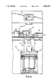
- FIG. 11 is a view similar to FIG. 6, but showing the weighing platform of the first station in its raised position supporting thereon a five-gallon can, which five-gallon can is retained via the exterior pins of the upper surface of the weighing platform;
- FIG. 28 is a schematic diagram showing the couplings between the tint-station and the base-station of each cell of the invention.
- FIGS. 30A and 30B are plan views of an automated plant incorporating a plurality of paint-batching cells according to the invention, incorporating a plurality of parallel cells for water-base processing, and one, isolated cell for oil-base processing.
- FIG. 1 the paint-batching machine or apparatus constituting part of each cell of the assembly of the present invention.
- Each machine 10 has a paint coloring agent batching and dispensing apparatus 12 operatively associated with a conveyer system 14 for transporting empty paint cans through the paint-batching machine in order to dispense the coloring agents and base(s) into the paint can.
- a conveyer system 14 for transporting empty paint cans through the paint-batching machine in order to dispense the coloring agents and base(s) into the paint can.
- the paint-batching apparatus 12 is an improved version of the paint-batching and dispensing machine produced by Miller Paint Equipment Company of Addison, Ill., which machine is generally referred to as "ACCUTINTER.”
- ACCUTINTER Such "ACCUTINTER” machine is conventionally provided with only one dispensing station, and it is computer-controlled in that all of the formulae representing the final paint colors are stored in relocatable memory of the computer, whereby by accessing any particular address of the computer memory representing the particular color or paint one desires, the "ACCUTINTER” will automatically dispense the proper amount of colorants and base to achieve such color.
- the first dispensing station 16 stores therein the various containers of coloring agents or liquid colorants, typically used and conventional in the paint manufacturing art.
- the first station includes 20 containers, each container having a volume of 5 gallons, with the corresponding number of dispensing nozzles associated therewith in the conventional manner.
- This first station 16 dispenses all of the colorants to be used in any particular color formula.
- the can-rotating mechanism 36 includes a first driven roller 38 rotatable in a horizontal plane, and positioned on the rearward portion of the conveying system, and a bifurcated idle-roller mechanism 40 defining a pair of idle-rollers 42, 44, also rotatable in a horizontal plane and movable toward and away from the conveying system via a piston 40', such that rearward movement of the bifurcated roller assembly 40 will urge the paint can towards the rear roller 38, and cause the rotation thereof during the driven rotation of the rear roller 38, as shown in FIGS. 16-18.
- the bar-code on the bottom of the paint can will, thereafter, be read by an optical bar-code reader of conventional design positioned below the station 32.
- the weighing mechanism is made up of a pair of vertically-oriented side plates 72, 74, seen in FIG. 12, the lower ends of which are affixed to a movable mounting block 76, which block 76 is reciprocal in the vertical direction via a cylinder piston arrangement 77.
- slots 13 and 15 are of a length slightly greater than the width of the side plates 72, 74, and which slots are positioned on each lateral side of the conveyer 20 at the first dispensing station.
- the conveyer 20 is of a width which is less than the width of the smaller container to be transported --the one-gallon paint cans-- there will be peripheral portions of the bottom of the paint can projecting laterally outwardly beyond the edges of the conveyer 20, which laterally outwardly projecting peripheral portions are those which are engaged by the upper edge surfaces 72', 74' of the side plates 72 and 74.
- the paint can, whether a one-gallon or five-gallon, is in its raised or elevated position on the upper edge surfaces 72', 74' of the side plates 72 and 74, in order that, after each dispensing of the wetting liquid base, or after each dispensing of a liquid colorant, such dispensing is weighed via the weighing mechanism 70 for quality-control purposes, as described below in greater detail.
- FIG. 11 shows a five-gallon paint can in its elevated position during dispensing, with the pins 78 in their retracted or downward-most states
- FIG. 9 shows a one-gallon can being dispensed and supported on the upper-edge surfaces 72', 74' of the weighing mechanism 70 and retained from any further lateral movement via the pins 78.
- the third, middle level is the system PLC (Programmable Logic Circuitry) which communicates with the VME and controls the operations of the conveyer system proper outside of cell-sites. This level controls the conveyer system from the accumulator area, where empty paint cans are stored for subsequent use, to the cell-site area, where the plurality of cells are arranged in parallel, this system PLC controlling the system gates for directing the pathways of the cans to the VME-chosen cell for each can.
- PLC Programmatic Logic Circuitry
- This system PLC also controls the outgoing-conveyer system, where the filled cans exiting from their respective cells are merged and conveyed, and controls the conveyance of these filled cans from the cell site to the palletizing area, where the filled cans are sorted by customer for loading onto pallets, and the like.
- the fourth, or lowest, level of the computer system is the Programmable Logic Circuitry (PLC) associated with each of the cells, each of which communications with the central VME for instructions.
- PLC Programmable Logic Circuitry
- the operation of the conveyer system at each cell is controlled by the local cell-PLC, which cell-PLC also, through the photodetectors above-described, controls the operation of can-rotating stations where the can is rotated and its bar-code read by the respective optical scanner, as well as the scanner itself, and also controls the operations of the piston-cylinders 79 for the raising and lowering of the weighing platform, as set forth above.
- the microprocessor-control of each "ACCUTINTER” which is conventional and presently-used on "ACCUTINTER” machines. This control, one at each station 16, 18, controls the motor and pump operations, and solenoid-valve openings.
- these local "ACCUTINTER" controls are subject to master control from the VME, as described below in great detail.
- the SUN System will send the product-run schedule to the VME at the plant cite (block 116), one can at a time, which includes all orders of paint cans for that day. If there is a "No-Go", a fault loop, shown in FIG. 19A, will determine if the fault has been cleared.
- the VME after receiving the schedule from the SUN System, sends information to a side-label printer (block 118), which side-label printer is conventional in the art and provides a physical label having the information written thereon as to the contents of the can, such as color, which label is attached to the can as it is conveyed out of accumulator-storage, as described below with regards to FIG. 30A.
- Block 120 indicates the information is also sent to the bar-code printer for developing a bar-code label to be attached to the bottom of the can on the bottom lid thereof, which bar-code label includes the general information as to the customer, relevant specifics, and so forth, such as line number, shipping point, formula, all of which is achieved by having the bar-code refer to a specific memory-address in the VME system, which memory-address is specific to that particular order, and includes therein, among other information, the formula for formulating the color desired for that paint can, which formula, of course, will control the operations of each station 16, 18 of each cell "ACCUTINTER", and the dispensing of the colorants and base to form the desired color.
- the bar-code label includes the general information as to the customer, relevant specifics, and so forth, such as line number, shipping point, formula, all of which is achieved by having the bar-code refer to a specific memory-address in the VME system, which memory-address is specific to that particular order, and includes therein, among other information
- Block 132 indicates that after the placement of the bar-code label on the bottom of the paint can, the can is conveyed and converged to the system input pail lift, where the paint can is elevated above floor level to an upper conveyer system for transport via an upper feed-conveyer (block 134) to the site of the plurality of parallel-arranged cells.
- the upper feed-conveyer will first convey the can to a first bar-code reader, where the previously-emplaced bar-code label is read, this first bar-code station having a stop-and-spin mechanism for rotating the can, in order for it to allow the bar-code optical scanner to read the bar-code, thereby providing the necessary information to the VME to process the can during its conveyance to the cell-site.
- the cell PLC Upon the initiation of the raising and completion thereof of the paint can via the weighing platform, with the can tared, the cell PLC will send a tint-prewet permissive request to both dispensing stations 16 and 18, for the readying thereof (block 172), while, thereafter, the central VME sends the prewet formula to the base-station (block 174) for the amount of liquid base to be dispensed from the second station 18 through the first station 16, as above described, in order to wet the bottom of the can (block 174).
- the prewet liquid base is dispensed (block 176), after which, the quality weight-loop control is activated to weigh the contents dispensed to make sure that the liquid base is in the proper amount.
- Blocks 182, 186) the platform at the first tint-station 16 is lowered (blocks 182, 186) for subsequent transporting of the can to the second base-station 18. If, however, any one of the dispensings of the liquid colorants has been determined to be in error, then an error signal is indicated (block 184), and the subroutine shown in FIG. 20 carried out.
- Blocks 186 through 198 show substantially the same process for the second base-station 18 as that done at the tint-station 16, where the can from the tint-station 16 is conveyed to the base-station's bar-code reader, where the can is detected, spun and then read by the optical bar-code reader (36 in FIG.
- the can is conveyed to a conventional lidder (block 212), where the can is lidded (block 214), and, thereafter, the can is conveyed to a diverter gate (block 216), where the can takes either one of two paths, depending on whether its a one-gallon can or a five-gallon can (block 218). If it is a one-gallon can, then the can is diverted and conveyed to a one-gallon conventional or automated paint mixer (block 220), whereas, if it is a five-gallon can, then the can is diverted and conveyed to one of two five-gallon can conventional or automated paint mixers (block 222).
- FIG. 20 shows the "Dispense Error" routine, starting with block 252, which routine is carried out when any dispensing of a colorant or liquid base has been determined to be of a quality-control weight outside of the tolerance-limits as described above with references to blocks 180, 184, and 208. If the quality-control weighing indicates "overweight" (block 254), then the VME system will send such information to the central SUN System (block 258), which will then attempt to calculate a correction formula for that paint can (block 260), and determine whether such is possible or not (block 262).
- the VME Upon receiving such a "cell error” input flag for the underdispensing of a liquid colorant or a base, the VME will send an error record to the central SUN System, which record will contain the type time and priority of the error indicated, (block 286), and, simultaneously therewith, will display it on the operator's console (block 288), after which, the VME will determine whether or not the cell error disables the cell or not (block 290).
- FIGS. 22A through 27 there is shown therein the flow charts for the actual dispensing of each of the liquid colorants and liquid base as well as the checking of each dispensing via the quality-control weighing thereof to determine the proper dispensing to produce a quality product.
- These flow charts are representative of the dispensing of each of the stations 16 and 18, and each dispensing at the tint-station 16, these flow charts being generally included by the blocks 176, 176' in FIG. 19C and block 206 in FIG. 19D, each dispense weight-loop indicated by these blocks being controlled by the flow charts in the FIGS. 22A through 27.
- Block 404 indicates a memory check, called cyclic redundancy check, which checks for the calibration constants, operating flags and supply canister levels of the particular tint-station 16 or base-station 18. If such check fails, then an error signal (block 404') is generated, which is discussed in greater detail when discussing FIG. 26. If the memory check clears, then a "purge" check (block 406) occurs, to see if each orifice of the respective station 16 and 18 requires clearing, or dispensing, in order to remove any of remaining colorants from the previous dispensing process.
- cyclic redundancy check which checks for the calibration constants, operating flags and supply canister levels of the particular tint-station 16 or base-station 18. If such check fails, then an error signal (block 404') is generated, which is discussed in greater detail when discussing FIG. 26. If the memory check clears, then a "purge" check (block 406) occurs, to see if each orifice of the respective station 16 and 18 requires clearing, or dispensing, in order to remove any of
- Block 410 The formula from the SUN System, if capable of being carried out on the machine, is split into two tables (block 410) one for the 0.1 gram resolution scale, and one for the 0.01 gram resolution scale, which is relevant at the tint-station 16, where there are two scale-heads employed, one having a resolution of 0.01 grams and one of 0.1 gram resolution.
- Block 412 indicates a check of the levels in the supply canisters in order to ensure that there is enough supply therein to dispense the required amount of liquid colorants or base for that specific formula. If not, then another bad end (block 414) ensures.
- block 416 there is a decision block where it is determined whether the system should wait for a "go" signal or not, a "go" signal being indicative of an automated run.
- connection is made to the 0.1 gram scale-head (block 434) so as to couple the 0.1 gram scale-head to the "ACCUTINTER", after which, the net weight of the can and its contents thereof are measured (block 436) where the levels thereof are compared to that stored in the formula in the relocatable memory to make sure none of the previously-dispensed liquids have spilled out, or the like. If all checks out (block 438), then the build-dispense masks commands are generated (block 440), which means that it is determined which of the pumps are to be used for the dispensing, which of the high speed valves, and so forth, for achieving the proper dispensing of the particular liquid colorant or base.
- the net weight is obtained (block 468), which is a tare weight, after which, the gross weight (block 470) is calculated to indicate the total weight of the paint can and the contents therein. Thereafter, referring to FIG. 22D, the decision (block 472) as to quality is carried out in order to determine whether the net weight is within the tolerance range required, dependent upon the 0.01 gram scale-head being used or the 0.01 gram scale-head used, if it is a tint-station, or a 1.0 gram scale-head if at the base-station.
- a "fake” weight is generated (block 490), thereby using the nominal weight being set forth int or base, as described above in the description of FIG. 20. If quality-control weight-checking is not used, then a "fake” weight is generated (block 490), thereby using the nominal weight being set forth in the formula (block 492) for updating the dispense records, where upon the level records are updated using this "fake” weight (block 494). Thereafter, the "next dispense” is generated (block 480), if there is such another one, and the flow returns back to block 448 in FIG. 22B.
- the "fake” weight is necessary in order to ensure that there is a proper monitoring of the supply levels of the colorants and base.
- the motor operation is continually monitored to ensure proper operation, and if such does not occur, then a "no-pulse" error is generated, as set forth above when discussing blocks 450 and 461.
- the error routine for the no pulses is shown in FIG. 23, indicated generally at the beginning by reference block 500.
- the system-routine checks to see if anything is dispensed (block 502), and if not, then appropriate post-dispense records are indicated in the post-dispense information area (block 504), while, if there were something dispensed at the particular station for the particular colorant or liquid base, then the logical decision is determined whether weight-checking is on or off (block 506).
- FIG. 25 indicates the flow chart for the "off sequence", which occurs after the last colorant has been dispensed at the particular dispensing station, as was indicated by block 452 in FIG. 22B.
- the "off sequence" (block 560) in FIG. 25 will first determine whether there is anything in the 0.01 gram table, which is relevant only to the first tint-station 16, where colorants to be dispensed in quantities less than 6.8 grams are coupled to the 0.01 gram resolution scale-head for determining the fine resolution thereof (block 562).
- the "end dispense" routine in FIG. 27 shows a logic-sequence of events when the dispensing of a particular colorant or base is ended at a particular station and nozzle thereof, or a bad-end or error-pulse generated.
- the scale-communications are disconnected (block 622), after which, the post-dispense levels of the containers are calculated, and the status thereof recorded in the VME for future use (block 624), and then an error determination is carried out (block 626), and if there was an error, a "clear state" is returned to and a simple error message display is shown (block 628). If there was an error from routine of FIG. 26 or from block 488 in FIG. 22D for an overdispensed ingredient for which a correction formula was not possible, then manual dispense is determined (blocks 630,634). Manual dispense also occurs when the formula was entered by hand at the "ACCUTINTER" keyboard input.
- the tint-station has its own CPU, which is similar to those conventionally used with "ACCUTINTERS", this CPU being coupled to the central VME via a terminal-node controller (block 712) for controlling the operation of the tint-station, as described above.
- the first tint-station 16 also has its scale-platform (block 701) with two scale-heads, as above described (blocks 722, 724), one for the 0.01 gram tolerance, and one for the 0.10 gram tolerance, with a scale-head relay (box 720) providing the switch over, all of which is controlled from the tint and base stations of the "ACCUTINTER" (block 740) via terminal-node controllers 708, 710.
- FIG. 29 shows the hardware connections of the entire system, with the Sun System (block 750), as described above, being coupled to the VME CPU (block 752, 754) with the system VME CPU being coupled to the CPU's of a plurality of "ACCUTINTERS", whether it be station 16 or 18 (block 756) each of which has the appropriate weight scales (block 758), as described above.
- the Sun System block 750
- the system VME CPU being coupled to the CPU's of a plurality of "ACCUTINTERS", whether it be station 16 or 18 (block 756) each of which has the appropriate weight scales (block 758), as described above.
- One "ACCUTINTER” is used for oil based paints, (blocks 760, 762); however, more may be added. Each station has its own weighing scale and associated control as set forth in FIG. 28.
- the central processing unit of the VME card cage (block 752') also, as described above, controls the message boards (block 764), printers (block 766), operator terminals (block 768), and the bar-code readers (block 770), all of which are of conventional design.
- the VME as described above, is tied to the system PLC which in turn is tied to the five cell PLC's (blocks 752', 773, 774, 776, 778 and 780).
- the can is conveyed to the bar-code labeler-machine 826, where the bar-code appropriate to that particular can is printed and attached to the bottom of the can, which bar-code represents the information containing the formula and other information thereon.
- the can is thereafter conveyed via conveyer 822 to a first pail-lift area 830, where the can is lifted from substantially floor-level to an elevated state thereabove, and conveyed along elevated conveyer 832 to the first bar-code reader 834, where the bar-code paint can is rotated and read by a conventional optical bar-code reader to indicate the appropriate formula in the computer system, to determine the appropriate path set aside for that particular paint can.
- the can Upon exiting a respective paint mixing machine, the can is conveyed along line-conveyer 844 if it is a one-gallon can, or line 846 if it is a five-gallon can, and directed onto the output-conveyer 850 for transport to the storage and palletizing area indicated generally by reference numeral 900 in FIG. 30B.
- the can's bar-code is read for the fourth and last time, at optical bar-code reader-station 902 to determine which of the palletizing tracks 904 through 914 the can is to be conveyed.
Abstract
Description
Claims (8)
Priority Applications (10)
| Application Number | Priority Date | Filing Date | Title |
|---|---|---|---|
| US07/432,991 US5083591A (en) | 1989-11-06 | 1989-11-06 | Process for dispensing liquid colorants into a paint can, and quality control therefor |
| CA002029228A CA2029228A1 (en) | 1989-11-06 | 1990-11-02 | Process and apparatus for dispensing liquid colorants into a paint can, and quality control therefor |
| EP95114250A EP0693310A3 (en) | 1989-11-06 | 1990-11-05 | Improvements in or relating to methods and apparatus for quality-control checking of the dispensing of paint ingredients |
| EP90312103A EP0427497A1 (en) | 1989-11-06 | 1990-11-05 | Process of formulating paint |
| KR1019900017919A KR910009343A (en) | 1989-11-06 | 1990-11-05 | Paint batching device |
| JP2300935A JPH0472196A (en) | 1989-11-06 | 1990-11-06 | Device and method for coating batch supply |
| AU65861/90A AU630247B2 (en) | 1989-11-06 | 1990-11-06 | Process and apparatus for dispensing liquid colorants into a paint can, and quality control therefor |
| US07/795,008 US5163484A (en) | 1989-11-06 | 1991-11-14 | Process and apparatus for dispensing liquid colorants into a paint can, and quality control therefor |
| US07/795,205 US5268849A (en) | 1989-11-06 | 1991-11-14 | Process and apparatus for dispensing liquid colorants into a paint can, and quality control therefor |
| US07/882,503 US5203387A (en) | 1989-11-06 | 1992-05-13 | Process and apparatus for dispensing liquid colorants into a paint can, and quality control therefor |
Applications Claiming Priority (1)
| Application Number | Priority Date | Filing Date | Title |
|---|---|---|---|
| US07/432,991 US5083591A (en) | 1989-11-06 | 1989-11-06 | Process for dispensing liquid colorants into a paint can, and quality control therefor |
Related Child Applications (2)
| Application Number | Title | Priority Date | Filing Date |
|---|---|---|---|
| US07/795,008 Division US5163484A (en) | 1989-11-06 | 1991-11-14 | Process and apparatus for dispensing liquid colorants into a paint can, and quality control therefor |
| US07/795,205 Division US5268849A (en) | 1989-11-06 | 1991-11-14 | Process and apparatus for dispensing liquid colorants into a paint can, and quality control therefor |
Publications (1)
| Publication Number | Publication Date |
|---|---|
| US5083591A true US5083591A (en) | 1992-01-28 |
Family
ID=23718407
Family Applications (1)
| Application Number | Title | Priority Date | Filing Date |
|---|---|---|---|
| US07/432,991 Expired - Fee Related US5083591A (en) | 1989-11-06 | 1989-11-06 | Process for dispensing liquid colorants into a paint can, and quality control therefor |
Country Status (6)
| Country | Link |
|---|---|
| US (1) | US5083591A (en) |
| EP (2) | EP0427497A1 (en) |
| JP (1) | JPH0472196A (en) |
| KR (1) | KR910009343A (en) |
| AU (1) | AU630247B2 (en) |
| CA (1) | CA2029228A1 (en) |
Cited By (75)
| Publication number | Priority date | Publication date | Assignee | Title |
|---|---|---|---|---|
| US5163484A (en) * | 1989-11-06 | 1992-11-17 | Dunn Edwards, Corp. & Fluid Management Ltd. Part. | Process and apparatus for dispensing liquid colorants into a paint can, and quality control therefor |
| US5203387A (en) * | 1989-11-06 | 1993-04-20 | Dunn Edwards Corp. & Fluid Management Ltd. Part. | Process and apparatus for dispensing liquid colorants into a paint can, and quality control therefor |
| US5266780A (en) * | 1990-08-10 | 1993-11-30 | Kansai Paint Company, Limited | Human error preventing system using bar code reading collations |
| US5268849A (en) * | 1989-11-06 | 1993-12-07 | Dunn-Edwards Corporation | Process and apparatus for dispensing liquid colorants into a paint can, and quality control therefor |
| US5305917A (en) * | 1992-11-19 | 1994-04-26 | Fluid Management Limited Partnership | Simultaneous dispensing apparatus |
| US5310257A (en) * | 1992-10-29 | 1994-05-10 | Fluid Management Limited Partnership | Mixing apparatus |
| WO1994020365A1 (en) * | 1993-03-05 | 1994-09-15 | Dunn-Edwards Corp. | Fluidic container filler apparatus |
| US5404920A (en) * | 1993-10-15 | 1995-04-11 | Custer; Joseph L. | Automated fluid charging apparatus |
| US5407100A (en) * | 1994-01-07 | 1995-04-18 | Fluid Management Limited Partnership | Dispensing apparatus with a moveable plate |
| US5460209A (en) * | 1993-12-08 | 1995-10-24 | Massachusetts Institute Of Technology | Automatic dispenser for dry ingredients |
| US5493840A (en) * | 1993-02-10 | 1996-02-27 | Imperial Chemical Industries Plc | Means for providing flowable colourant in a coating composition |
| US5532942A (en) * | 1991-07-08 | 1996-07-02 | Shin-Etsu Chemical Co., Ltd. | Automatic apparatus for inspecting powdery product |
| US5682930A (en) * | 1993-11-03 | 1997-11-04 | Diversey Corporation | Automated dispenser |
| US5689415A (en) * | 1992-06-01 | 1997-11-18 | Ducost Engineering Ltd. | Control of paint spraying machines and the like |
| US6148877A (en) * | 1999-04-22 | 2000-11-21 | Bethke; Steven D. | Fluid filling system with fill time optimization |
| US6330487B1 (en) * | 1997-11-10 | 2001-12-11 | Raimar A. Jahn | Computerized virtual paint manufacturing and application system |
| US6412658B1 (en) | 2001-06-01 | 2002-07-02 | Imx Labs, Inc. | Point-of-sale body powder dispensing system |
| US20030093171A1 (en) * | 2001-07-19 | 2003-05-15 | Creative Edge Design Group, Ltd. | Flexible label printing assembly |
| US20030145901A1 (en) * | 2000-05-25 | 2003-08-07 | Laurent Noell | Method for packaging in a container a product containing different miscible ingredients |
| US6615881B2 (en) | 2001-09-24 | 2003-09-09 | Imx Labs, Inc. | Apparatus and method for custom cosmetic dispensing |
| US6622064B2 (en) | 2000-03-31 | 2003-09-16 | Imx Labs, Inc. | Nail polish selection method |
| US6659349B1 (en) * | 1996-03-23 | 2003-12-09 | Bayerische Motoren Werke Aktiengesellschaft | Device for identifying objects |
| US6672341B2 (en) | 2001-09-24 | 2004-01-06 | Imx Labs, Inc. | Apparatus and method for custom cosmetic dispensing |
| US20040216804A1 (en) * | 2002-07-26 | 2004-11-04 | Gfi, Innovations | Methodology and apparatus for storing and dispensing liquid components to create custom formulations |
| US20050017024A1 (en) * | 2003-07-24 | 2005-01-27 | Miller William A. | Sanitizable piston pumps and dispensing systems incorporating the same |
| US20050087545A1 (en) * | 2003-10-27 | 2005-04-28 | Petrus Engels Marcel H. | Apparatus for dispensing a plurality of fluids and container for use in the same |
| US20050092386A1 (en) * | 2003-10-30 | 2005-05-05 | Kaufhold Kenneth R. | Combination gravimetric and volumetric dispenser for multiple fluids |
| US20050160077A1 (en) * | 1999-10-06 | 2005-07-21 | Howes John L. | Paint manufacturing systems |
| US6935386B2 (en) | 2003-10-30 | 2005-08-30 | Fluid Management, Inc. | Automated cosmetics dispenser for point of sale cosmetics products |
| US20050205154A1 (en) * | 2004-03-16 | 2005-09-22 | Cleveland James R | Articulated nozzle closure for fluid dispensers |
| US20050247730A1 (en) * | 2004-05-07 | 2005-11-10 | Post Jan H | Apparatus for dispensing a plurality of powders and method of compounding substances |
| US20050252934A1 (en) * | 2004-05-12 | 2005-11-17 | Miller William A | Apparatus for dispensing paint and stain samples and methods of dispensing paint and stain samples |
| US20060024342A1 (en) * | 2004-07-19 | 2006-02-02 | Bartholomew Julie R | Customized retail point of sale dispensing methods |
| US20060087914A1 (en) * | 2004-10-25 | 2006-04-27 | Eckart Edmund A Jr | Automated mixing machine for paint bases and colorants |
| US20060148967A1 (en) * | 1998-12-23 | 2006-07-06 | Mcclain C D | Method and apparatus for producing an aqueous paint composition from a plurality of premixed compositions |
| US20070095421A1 (en) * | 2003-10-30 | 2007-05-03 | Fluid Management, Inc. | Combination Gravimetric and Volumetric Dispenser for Multiple Fluids |
| US7311223B2 (en) | 2004-05-07 | 2007-12-25 | Fluid Management, Inc. | Apparatus for dispensing a plurality of powders and method of compounding substances |
| US20080047972A1 (en) * | 2001-06-01 | 2008-02-28 | Bartholomew Julie R | Point-of-sale body powder dispensing system |
| US20080210582A1 (en) * | 2007-03-02 | 2008-09-04 | The Sherwin-Williams Company | Inhibition of paint-product skin formation |
| US20080210774A1 (en) * | 2007-03-02 | 2008-09-04 | Ultrablend, Llc | Apparatus and method for humidifying a nozzle of a colorant dispenser |
| US20080269950A1 (en) * | 2004-06-30 | 2008-10-30 | Cps Color Equipment Spa Con Unico Socio | Device and Method for Mixing a Fluid Product Contained in a Closed Container |
| US20080271809A1 (en) * | 2007-03-15 | 2008-11-06 | The Coca-Cola Company | Multiple Stream Filling System |
| US20090120306A1 (en) * | 2007-08-23 | 2009-05-14 | Decarlo John M | Systems and methods of mixing and cooling food products |
| US20090223997A1 (en) * | 2003-03-21 | 2009-09-10 | Gfi Innovations, Inc. | Methodology and Apparatus for Storing and Dispensing Liquid Components to Create Custom Formulations |
| US7624769B2 (en) | 2004-11-08 | 2009-12-01 | Cosmetic Technologies, L.L.C. | Automated customized cosmetic dispenser |
| US20090316521A1 (en) * | 2008-06-20 | 2009-12-24 | Red Devil Equipment Company | Pounding station |
| US7640755B1 (en) * | 2003-02-07 | 2010-01-05 | Moobella, Llc | Dynamic process control |
| US20100030355A1 (en) * | 2008-02-04 | 2010-02-04 | The Coca-Cola Company | Methods of creating customized beverage products |
| US20100043919A1 (en) * | 2006-12-22 | 2010-02-25 | Jean-Pierre Solignac | Machine for the automated production of compositions of raw materials such as liquids, powders or pastes in a mobile tank |
| US20110010255A1 (en) * | 2009-07-10 | 2011-01-13 | Mario Drocco | Dispensing and mixing line and method for products |
| US20120060965A1 (en) * | 2010-07-27 | 2012-03-15 | Krones Ag | Apparatus and Method for Bottling Multi-Component Beverages |
| US20120285582A1 (en) * | 2009-11-20 | 2012-11-15 | Pentii Airaksinen | Paint mixing machine |
| US20130074982A1 (en) * | 2011-09-28 | 2013-03-28 | Gfi Innovations, Inc. | Methodology and Apparatus for Storing and Dispensing Liquid Components to Create Custom Formulations |
| US20130111849A1 (en) * | 2009-11-16 | 2013-05-09 | Cps Color Equipment Spa Con Unico Socio | Paint sample mixing and vending machine |
| US20130158704A1 (en) * | 2011-12-16 | 2013-06-20 | Randall L. Hughes | Method and apparatus for producing paint |
| US8573263B2 (en) | 2001-09-24 | 2013-11-05 | Cosmetic Technologies, Llc | Apparatus and method for custom cosmetic dispensing |
| US20130313134A1 (en) * | 2010-06-24 | 2013-11-28 | Cps Color Equipment Spa Con Unico Socio | Anti-drying device |
| US8708202B2 (en) | 2011-05-10 | 2014-04-29 | Ppg Industries Ohio, Inc. | Pressure canisters for automated delivery of coating compositions |
| US8739840B2 (en) | 2010-04-26 | 2014-06-03 | The Coca-Cola Company | Method for managing orders and dispensing beverages |
| US8757222B2 (en) | 2010-04-26 | 2014-06-24 | The Coca-Cola Company | Vessel activated beverage dispenser |
| US20140222180A1 (en) * | 2013-02-01 | 2014-08-07 | Mettler-Toledo, LLC | Batch conversion |
| US8807393B2 (en) | 2006-03-06 | 2014-08-19 | The Coca-Cola Company | Beverage dispensing system |
| US20160101395A1 (en) * | 2013-05-15 | 2016-04-14 | Alaa Hussain | Liquid mixer for mixing nail polish |
| US9394153B2 (en) | 2007-03-15 | 2016-07-19 | The Coca-Cola Company | Multiple stream filling system |
| EP3225301A1 (en) * | 2016-03-07 | 2017-10-04 | w&p Baustoffe GmbH | Assembly for the production of pigmented mixtures |
| US9849431B2 (en) | 2012-07-13 | 2017-12-26 | Ppg Industries Ohio, Inc. | System and method for automated production, application and evaluation of coating compositions |
| EP3586951A1 (en) * | 2018-06-28 | 2020-01-01 | Jauhetekniikka Oy | Dispensing apparatus and method for forming a mixture of materials and use |
| CN111771174A (en) * | 2018-02-20 | 2020-10-13 | 德罗蒙特股份公司 | Method for controlling a reservoir of a processing line for dosing containers for fluid products |
| WO2020212801A1 (en) * | 2019-04-13 | 2020-10-22 | Sathe Sandip | A point-of-sale paint tinting equipment |
| DE102019125708A1 (en) * | 2019-09-24 | 2021-03-25 | Hicham Najjari | System for the automated filling of individualized products |
| US11344856B2 (en) * | 2017-05-19 | 2022-05-31 | Basf Coatings Gmbh | Modular production system and method for producing formulations |
| US11412835B2 (en) | 2015-06-08 | 2022-08-16 | Cosmetic Technologies, L.L.C. | Automated delivery system of a cosmetic sample |
| US20230071789A1 (en) * | 2020-10-01 | 2023-03-09 | Alfa S.R.L. | Machine for preparing fluid products and method for preparing a formulation of fluid products by means of such a machine |
| US11603307B2 (en) * | 2019-03-01 | 2023-03-14 | L'oreal | Custom hair dye dispensing system and intermediate bulk container for storing a bulk hair dye |
| US11865502B2 (en) * | 2017-04-17 | 2024-01-09 | Swimc Llc | Systems and methods for paint tinting |
Families Citing this family (24)
| Publication number | Priority date | Publication date | Assignee | Title |
|---|---|---|---|---|
| IT1265210B1 (en) * | 1993-11-22 | 1996-10-31 | Ind Automation Systems | EQUIPMENT FOR THE DISPENSING OF FLUID SUBSTANCES TO BE MIXED |
| DE19540449C2 (en) * | 1995-10-30 | 1997-11-20 | Ralf Hildenbrand | Dosing process and dosing system |
| NL1006911C2 (en) * | 1997-09-02 | 1999-03-04 | Gerritse Beheer Bv | Device for metered dispensing of a number of different liquid or pasty masses. |
| GB2342457A (en) * | 1998-10-07 | 2000-04-12 | John Clark | A quality control sampling system with barcode reader and video camera |
| AU3662599A (en) * | 1999-04-23 | 2000-11-10 | Tetra Laval Holdings & Finance Sa | Multi-product packaging machine and method with bar code reader |
| EP1057522B1 (en) | 1999-05-31 | 2004-07-21 | Kikusui Chemical Industries Co., Ltd., Kozuka Bldg. | Method for manufacturing/handling fluid component packaged goods, manufacture/handling instructing data code for use in this method and fluid component packaged goods affixed by this manufacture/handlung instructing data code |
| EP1318441A3 (en) * | 1999-05-31 | 2004-07-28 | Kikusui Chemical Industries Co., Ltd., Kozuka Bldg. | Method for manufacturing/handling fluid component packaged goods, manufacture/handling instructing data code for use in this method and fluid component packaged goods affixed by this manufacture/handling instructing data code |
| IT1321014B1 (en) | 2000-02-15 | 2003-12-18 | Corob Spa | CONTAINER TRANSPORT SYSTEM, PARTICULARLY SUITABLE FOR THE USE OF A PLANT FOR THE PRODUCTION OF PAINTS, PAINTS AND |
| JP4718035B2 (en) * | 2001-04-18 | 2011-07-06 | 東洋自動機株式会社 | Filling device |
| EP1558072A4 (en) * | 2002-10-21 | 2007-05-02 | Pidilite Ind Ltd | A device for instant manufacture of customized paint, a control system for use in the said device and a process for making the paint using the device |
| GB0501100D0 (en) * | 2005-01-19 | 2005-02-23 | Bp Chem Int Ltd | Process |
| US7690405B2 (en) * | 2005-07-18 | 2010-04-06 | Fluid Management, Inc. | Multiple fluid dispenser |
| GB0515179D0 (en) * | 2005-07-25 | 2005-08-31 | Ici Plc | A method of producing a coating composition |
| EP1820568A1 (en) * | 2006-02-21 | 2007-08-22 | Degussa GmbH | Container for liquid paint comprising a machine-readable storing medium, and method for metering liquid paint |
| US8141599B2 (en) | 2008-06-17 | 2012-03-27 | Valspar Sourcing, Inc. | Expanded color space architectural paint and stain tinting system |
| AT510746B1 (en) * | 2011-07-14 | 2013-07-15 | W & P Baustoffe Gmbh | METHOD AND APPARATUS FOR MEASURING THE COLOR OF PRODUCTS |
| EP3056264B1 (en) * | 2015-02-13 | 2023-05-10 | Betek Boya ve Kimya Sanayi A.S. | Tinting method and tinting machine |
| CN105440765A (en) * | 2015-07-31 | 2016-03-30 | 上海振华重工(集团)常州油漆有限公司 | Paint mixing tank for epoxy anti-corrosion paint |
| CN108854836A (en) * | 2018-05-10 | 2018-11-23 | 深圳市大能智造科技有限公司 | A kind of automatic powder liquid proportion machine |
| CN108972893A (en) * | 2018-06-12 | 2018-12-11 | 王丹丹 | A kind of build concrete proportioning machine of adjustable freight volume |
| CN108714970A (en) * | 2018-06-12 | 2018-10-30 | 安徽特斯艾尔机电设备有限公司 | It is a kind of can remote adjustment freight volume build concrete proportioning machine |
| KR102563377B1 (en) * | 2018-09-17 | 2023-08-07 | 정저우 산화 테크놀로지 앤 인더스트리 컴퍼니 리미티드 | Automotive refinish paint weight volume mixing color matching method, material acquisition mechanism and automatic color mixer |
| CN112007565A (en) * | 2020-08-20 | 2020-12-01 | 广东立乔交通工程有限公司 | Synthesis device and synthesis method of reflective coating of high-speed guardrail |
| CN114367242B (en) * | 2022-01-26 | 2023-05-12 | 广东信一科技有限公司 | On-orbit intelligent conveying system for mixed materials |
Citations (22)
| Publication number | Priority date | Publication date | Assignee | Title |
|---|---|---|---|---|
| US2787402A (en) * | 1952-04-16 | 1957-04-02 | Color Carousel Corp | Liquid proportioning and dispensing apparatus |
| US2848019A (en) * | 1953-10-27 | 1958-08-19 | Color Carousel Corp | Paint mixing machine |
| US3029847A (en) * | 1958-09-02 | 1962-04-17 | Valspar Corp | Dispensing apparatus |
| US3066830A (en) * | 1958-02-24 | 1962-12-04 | Valspar Corp | Dispensing machine |
| DE1473125A1 (en) * | 1962-06-29 | 1969-01-02 | Lyle Marsh | Liquid measuring and dispensing device |
| US3670785A (en) * | 1970-07-02 | 1972-06-20 | Valspar Corp | Method and apparatus for tinting paint |
| US3959636A (en) * | 1975-03-10 | 1976-05-25 | Mangood Corporation | Batching system |
| US4109143A (en) * | 1976-06-18 | 1978-08-22 | Matsushita Electric Industrial Co., Ltd. | Optical reader |
| US4230266A (en) * | 1979-04-25 | 1980-10-28 | Owens-Illinois, Inc. | Method and apparatus of cavity identification of mold of origin of a glass container |
| US4335759A (en) * | 1979-05-10 | 1982-06-22 | Winter Osakeyhtio | Method of mixing paints and their toners |
| US4525071A (en) * | 1984-05-31 | 1985-06-25 | Crawford & Russell, Inc. | Additive inventory control, batching and delivery system |
| US4554955A (en) * | 1983-05-25 | 1985-11-26 | Campbell Soup Company | Method and apparatus for assembling food ingredients |
| US4563739A (en) * | 1983-07-18 | 1986-01-07 | Impulse Computer Systems, Inc. | Inventory and business management system which accounts for the contents of full and partially filled product containers |
| US4585148A (en) * | 1983-02-05 | 1986-04-29 | Nippon Paint Co., Ltd. | Process and apparatus for metering liquid colorant |
| US4588880A (en) * | 1982-09-16 | 1986-05-13 | Robert Bosch Gmbh | Non-contacting code recognition system for code carriers on production line workpieces |
| US4642470A (en) * | 1983-02-07 | 1987-02-10 | A/S Tomra Systems | Method and an apparatus for the identification of metal cans |
| US4705083A (en) * | 1984-10-12 | 1987-11-10 | Corob S.R.L. Automatic Machinery Project | Method and machine for batching coloring agents into paints and varnishes |
| US4804024A (en) * | 1987-05-13 | 1989-02-14 | Gerhard Arnemann | Apparatus for filling containers with a flowable medium |
| US4827993A (en) * | 1986-10-28 | 1989-05-09 | Nippon Paint Co., Ltd. | Automatic carrying and metering system for liquid reservoir |
| US4913198A (en) * | 1987-10-05 | 1990-04-03 | Japan Exlan Company, Ltd. | System for automatic dispensation of dye solution |
| WO1990005666A2 (en) * | 1988-11-14 | 1990-05-31 | Oden Corporation | Precision filling machine |
| US4967938A (en) * | 1989-07-17 | 1990-11-06 | Fluid Management Limited Partnership | Paint dispensing apparatus |
Family Cites Families (13)
| Publication number | Priority date | Publication date | Assignee | Title |
|---|---|---|---|---|
| FR2155822B3 (en) * | 1971-10-07 | 1974-06-07 | Roussillon Alimentaire | |
| US4046287A (en) * | 1976-05-10 | 1977-09-06 | Graco Inc. | Automatic metering and dispensing system |
| US4323097A (en) * | 1979-03-29 | 1982-04-06 | Achen John J | Turntable for colorant dispensers |
| CH642744A5 (en) * | 1981-07-29 | 1984-04-30 | Dec Engineering Sa | Method for metering a mixture |
| DE3201221A1 (en) * | 1982-01-16 | 1983-07-28 | Walter 4600 Dortmund Ribic | Station for mixing in particular paints and the like |
| EP0099252A2 (en) * | 1982-07-09 | 1984-01-25 | INTERNATIONAL PAINT public limited company | Apparatus for forming mixtures of fluids |
| US4494583A (en) * | 1983-05-16 | 1985-01-22 | Velasco Scale Company | Bung alignment apparatus |
| IT1182287B (en) * | 1984-09-26 | 1987-10-05 | Montelera Spa | PLANT FOR THE PRODUCTION OF LIQUID OR SEMI-LIQUID PRINTING INKS OF QUALITY AND DIFFERENT COLORS |
| JPS6350311Y2 (en) * | 1984-11-16 | 1988-12-23 | ||
| GB8518852D0 (en) * | 1985-07-25 | 1985-08-29 | Coop Wholesale | Filling bottles |
| US4667503A (en) * | 1985-12-11 | 1987-05-26 | Monarch Specialty Systems, Inc. | Method of calibrating volumetric metering and blending device |
| US4733971A (en) * | 1986-02-26 | 1988-03-29 | Micro Chemical, Inc. | Programmable weight sensitive microingredient feed additive delivery system and method |
| JPS63281989A (en) * | 1987-05-13 | 1988-11-18 | 三菱重工業株式会社 | Two-step filler |
-
1989
- 1989-11-06 US US07/432,991 patent/US5083591A/en not_active Expired - Fee Related
-
1990
- 1990-11-02 CA CA002029228A patent/CA2029228A1/en not_active Abandoned
- 1990-11-05 KR KR1019900017919A patent/KR910009343A/en not_active Application Discontinuation
- 1990-11-05 EP EP90312103A patent/EP0427497A1/en not_active Withdrawn
- 1990-11-05 EP EP95114250A patent/EP0693310A3/en not_active Withdrawn
- 1990-11-06 JP JP2300935A patent/JPH0472196A/en active Pending
- 1990-11-06 AU AU65861/90A patent/AU630247B2/en not_active Ceased
Patent Citations (22)
| Publication number | Priority date | Publication date | Assignee | Title |
|---|---|---|---|---|
| US2787402A (en) * | 1952-04-16 | 1957-04-02 | Color Carousel Corp | Liquid proportioning and dispensing apparatus |
| US2848019A (en) * | 1953-10-27 | 1958-08-19 | Color Carousel Corp | Paint mixing machine |
| US3066830A (en) * | 1958-02-24 | 1962-12-04 | Valspar Corp | Dispensing machine |
| US3029847A (en) * | 1958-09-02 | 1962-04-17 | Valspar Corp | Dispensing apparatus |
| DE1473125A1 (en) * | 1962-06-29 | 1969-01-02 | Lyle Marsh | Liquid measuring and dispensing device |
| US3670785A (en) * | 1970-07-02 | 1972-06-20 | Valspar Corp | Method and apparatus for tinting paint |
| US3959636A (en) * | 1975-03-10 | 1976-05-25 | Mangood Corporation | Batching system |
| US4109143A (en) * | 1976-06-18 | 1978-08-22 | Matsushita Electric Industrial Co., Ltd. | Optical reader |
| US4230266A (en) * | 1979-04-25 | 1980-10-28 | Owens-Illinois, Inc. | Method and apparatus of cavity identification of mold of origin of a glass container |
| US4335759A (en) * | 1979-05-10 | 1982-06-22 | Winter Osakeyhtio | Method of mixing paints and their toners |
| US4588880A (en) * | 1982-09-16 | 1986-05-13 | Robert Bosch Gmbh | Non-contacting code recognition system for code carriers on production line workpieces |
| US4585148A (en) * | 1983-02-05 | 1986-04-29 | Nippon Paint Co., Ltd. | Process and apparatus for metering liquid colorant |
| US4642470A (en) * | 1983-02-07 | 1987-02-10 | A/S Tomra Systems | Method and an apparatus for the identification of metal cans |
| US4554955A (en) * | 1983-05-25 | 1985-11-26 | Campbell Soup Company | Method and apparatus for assembling food ingredients |
| US4563739A (en) * | 1983-07-18 | 1986-01-07 | Impulse Computer Systems, Inc. | Inventory and business management system which accounts for the contents of full and partially filled product containers |
| US4525071A (en) * | 1984-05-31 | 1985-06-25 | Crawford & Russell, Inc. | Additive inventory control, batching and delivery system |
| US4705083A (en) * | 1984-10-12 | 1987-11-10 | Corob S.R.L. Automatic Machinery Project | Method and machine for batching coloring agents into paints and varnishes |
| US4827993A (en) * | 1986-10-28 | 1989-05-09 | Nippon Paint Co., Ltd. | Automatic carrying and metering system for liquid reservoir |
| US4804024A (en) * | 1987-05-13 | 1989-02-14 | Gerhard Arnemann | Apparatus for filling containers with a flowable medium |
| US4913198A (en) * | 1987-10-05 | 1990-04-03 | Japan Exlan Company, Ltd. | System for automatic dispensation of dye solution |
| WO1990005666A2 (en) * | 1988-11-14 | 1990-05-31 | Oden Corporation | Precision filling machine |
| US4967938A (en) * | 1989-07-17 | 1990-11-06 | Fluid Management Limited Partnership | Paint dispensing apparatus |
Cited By (138)
| Publication number | Priority date | Publication date | Assignee | Title |
|---|---|---|---|---|
| US5203387A (en) * | 1989-11-06 | 1993-04-20 | Dunn Edwards Corp. & Fluid Management Ltd. Part. | Process and apparatus for dispensing liquid colorants into a paint can, and quality control therefor |
| US5268849A (en) * | 1989-11-06 | 1993-12-07 | Dunn-Edwards Corporation | Process and apparatus for dispensing liquid colorants into a paint can, and quality control therefor |
| US5163484A (en) * | 1989-11-06 | 1992-11-17 | Dunn Edwards, Corp. & Fluid Management Ltd. Part. | Process and apparatus for dispensing liquid colorants into a paint can, and quality control therefor |
| US5266780A (en) * | 1990-08-10 | 1993-11-30 | Kansai Paint Company, Limited | Human error preventing system using bar code reading collations |
| US5532942A (en) * | 1991-07-08 | 1996-07-02 | Shin-Etsu Chemical Co., Ltd. | Automatic apparatus for inspecting powdery product |
| US5689415A (en) * | 1992-06-01 | 1997-11-18 | Ducost Engineering Ltd. | Control of paint spraying machines and the like |
| US5310257A (en) * | 1992-10-29 | 1994-05-10 | Fluid Management Limited Partnership | Mixing apparatus |
| US5305917A (en) * | 1992-11-19 | 1994-04-26 | Fluid Management Limited Partnership | Simultaneous dispensing apparatus |
| US5493840A (en) * | 1993-02-10 | 1996-02-27 | Imperial Chemical Industries Plc | Means for providing flowable colourant in a coating composition |
| WO1994020365A1 (en) * | 1993-03-05 | 1994-09-15 | Dunn-Edwards Corp. | Fluidic container filler apparatus |
| US5365722A (en) * | 1993-03-05 | 1994-11-22 | Dunn-Edwards Corp. | Method and apparatus for filling a container with a fluid |
| US5404920A (en) * | 1993-10-15 | 1995-04-11 | Custer; Joseph L. | Automated fluid charging apparatus |
| US5682930A (en) * | 1993-11-03 | 1997-11-04 | Diversey Corporation | Automated dispenser |
| US5460209A (en) * | 1993-12-08 | 1995-10-24 | Massachusetts Institute Of Technology | Automatic dispenser for dry ingredients |
| US5407100A (en) * | 1994-01-07 | 1995-04-18 | Fluid Management Limited Partnership | Dispensing apparatus with a moveable plate |
| US6659349B1 (en) * | 1996-03-23 | 2003-12-09 | Bayerische Motoren Werke Aktiengesellschaft | Device for identifying objects |
| US6330487B1 (en) * | 1997-11-10 | 2001-12-11 | Raimar A. Jahn | Computerized virtual paint manufacturing and application system |
| US7654727B2 (en) * | 1998-12-23 | 2010-02-02 | Coatings Management Systems, Inc. | Method and apparatus for producing an aqueous paint composition from a plurality of premixed compositions |
| US7619023B2 (en) | 1998-12-23 | 2009-11-17 | Coatings Management Systems, Inc. | Method and apparatus for producing an aqueous paint composition from a plurality of premixed compositions |
| US20080146699A1 (en) * | 1998-12-23 | 2008-06-19 | Coatings Management Systems Inc. | Method and apparatus for producing an aqueous paint composition from a plurality of premixed compositions |
| US20060148967A1 (en) * | 1998-12-23 | 2006-07-06 | Mcclain C D | Method and apparatus for producing an aqueous paint composition from a plurality of premixed compositions |
| US6148877A (en) * | 1999-04-22 | 2000-11-21 | Bethke; Steven D. | Fluid filling system with fill time optimization |
| US7571122B2 (en) | 1999-10-06 | 2009-08-04 | Colors Direct, L.L.C. | Paint manufacturing systems |
| US20050160077A1 (en) * | 1999-10-06 | 2005-07-21 | Howes John L. | Paint manufacturing systems |
| US6959284B1 (en) | 1999-10-06 | 2005-10-25 | John L. Howes | Containerized liquid coating product supply business method |
| US8880218B2 (en) | 2000-03-31 | 2014-11-04 | Cosmetic Technologies, L.L.C. | Nail polish color selection system |
| US20040143367A1 (en) * | 2000-03-31 | 2004-07-22 | Imx Labs, Inc. | Nail polish color selection system |
| US8352070B2 (en) | 2000-03-31 | 2013-01-08 | Cosmetic Technologies, Llc | Nail polish color selection system |
| US20110231267A1 (en) * | 2000-03-31 | 2011-09-22 | Cosmetic Technologies, L.L.C. | Nail polish color selection system |
| US7099740B2 (en) | 2000-03-31 | 2006-08-29 | Bartholomew Julie R | Nail polish color selection system |
| US7395134B2 (en) | 2000-03-31 | 2008-07-01 | Cosmetic Technologies, L.L.C. | Nail polish color selection system |
| US6622064B2 (en) | 2000-03-31 | 2003-09-16 | Imx Labs, Inc. | Nail polish selection method |
| US7822504B2 (en) | 2000-03-31 | 2010-10-26 | Cosmetic Technologies, L.L.C. | Nail polish color selection system |
| US20060283521A1 (en) * | 2000-03-31 | 2006-12-21 | Bartholomew Julie R | Nail polish color selection system |
| US20080234860A1 (en) * | 2000-03-31 | 2008-09-25 | Cosmetic Technologies, Llc | Nail polish color selection system |
| US20030145901A1 (en) * | 2000-05-25 | 2003-08-07 | Laurent Noell | Method for packaging in a container a product containing different miscible ingredients |
| US6729361B2 (en) * | 2000-05-25 | 2004-05-04 | Serac | Method for packaging in a container a product containing different miscible ingredients |
| US20080047972A1 (en) * | 2001-06-01 | 2008-02-28 | Bartholomew Julie R | Point-of-sale body powder dispensing system |
| US7121429B2 (en) | 2001-06-01 | 2006-10-17 | Bartholomew Julie R | Point-of-sale body powder dispensing system |
| US20040245263A1 (en) * | 2001-06-01 | 2004-12-09 | Imx Labs, Inc. | Point-of-sale body powder dispensing system |
| US8636173B2 (en) | 2001-06-01 | 2014-01-28 | Cosmetic Technologies, L.L.C. | Point-of-sale body powder dispensing system |
| US6412658B1 (en) | 2001-06-01 | 2002-07-02 | Imx Labs, Inc. | Point-of-sale body powder dispensing system |
| US6779686B2 (en) | 2001-06-01 | 2004-08-24 | Imx Labs, Inc. | Point-of-sale body powder dispensing system |
| US20030093171A1 (en) * | 2001-07-19 | 2003-05-15 | Creative Edge Design Group, Ltd. | Flexible label printing assembly |
| US8141596B2 (en) | 2001-09-24 | 2012-03-27 | Cosmetic Technologies Llc | Apparatus and method for custom cosmetic dispensing |
| US8573263B2 (en) | 2001-09-24 | 2013-11-05 | Cosmetic Technologies, Llc | Apparatus and method for custom cosmetic dispensing |
| US6672341B2 (en) | 2001-09-24 | 2004-01-06 | Imx Labs, Inc. | Apparatus and method for custom cosmetic dispensing |
| US7082970B2 (en) | 2001-09-24 | 2006-08-01 | Bartholomew Julie R | Apparatus and method for custom cosmetic dispensing |
| US20050067425A1 (en) * | 2001-09-24 | 2005-03-31 | Imx Labs, Inc. | Apparatus and method for custom cosmetic dispensing |
| US6615881B2 (en) | 2001-09-24 | 2003-09-09 | Imx Labs, Inc. | Apparatus and method for custom cosmetic dispensing |
| US6883561B2 (en) | 2001-09-24 | 2005-04-26 | Imx Labs, Inc. | Apparatus and method for custom cosmetic dispensing |
| US7475710B2 (en) | 2001-09-24 | 2009-01-13 | Bartholomew Julie R | Apparatus and method for custom cosmetic dispensing |
| US20040108015A1 (en) * | 2001-09-24 | 2004-06-10 | Imx Labs, Inc. | Apparatus and method for custom cosmetic dispensing |
| US7198073B2 (en) * | 2002-07-26 | 2007-04-03 | Gfi, Innovations | Methodology and apparatus for storing and dispensing liquid components to create custom formulations |
| US20040216804A1 (en) * | 2002-07-26 | 2004-11-04 | Gfi, Innovations | Methodology and apparatus for storing and dispensing liquid components to create custom formulations |
| US7640755B1 (en) * | 2003-02-07 | 2010-01-05 | Moobella, Llc | Dynamic process control |
| US20110017773A1 (en) * | 2003-03-21 | 2011-01-27 | Gfi Innovations, Inc. | Methodology and Apparatus for Storing and Dispensing Liquid Components to Create Custom Formulations |
| US20090223997A1 (en) * | 2003-03-21 | 2009-09-10 | Gfi Innovations, Inc. | Methodology and Apparatus for Storing and Dispensing Liquid Components to Create Custom Formulations |
| US7789111B2 (en) | 2003-03-21 | 2010-09-07 | Gfi Innovations, Inc. | Methodology and apparatus for storing and dispensing liquid components to create custom formulations |
| US8011394B2 (en) | 2003-03-21 | 2011-09-06 | Gfi Innovations, Inc. | Methodology and apparatus for storing and dispensing liquid components to create custom formulations |
| US20050017024A1 (en) * | 2003-07-24 | 2005-01-27 | Miller William A. | Sanitizable piston pumps and dispensing systems incorporating the same |
| US6945431B2 (en) | 2003-07-24 | 2005-09-20 | Fluid Management, Inc. | Sanitizable piston pumps and dispensing systems incorporating the same |
| US20050087545A1 (en) * | 2003-10-27 | 2005-04-28 | Petrus Engels Marcel H. | Apparatus for dispensing a plurality of fluids and container for use in the same |
| US7360564B2 (en) | 2003-10-27 | 2008-04-22 | Fluid Management, Inc. | Apparatus for dispensing a plurality of fluids and container for use in the same |
| US7347344B2 (en) | 2003-10-27 | 2008-03-25 | Fluid Management Operation Llc | Apparatus for dispensing a plurality of fluids and container for use in the same |
| US20070095421A1 (en) * | 2003-10-30 | 2007-05-03 | Fluid Management, Inc. | Combination Gravimetric and Volumetric Dispenser for Multiple Fluids |
| US20060086405A1 (en) * | 2003-10-30 | 2006-04-27 | Fluid Management Operations Llc | Combination gravimetric and volumetric dispenser for multiple fluids |
| US6991004B2 (en) | 2003-10-30 | 2006-01-31 | Fluid Management, Inc. | Combination gravimetric and volumetric dispenser for multiple fluids |
| US7918435B2 (en) | 2003-10-30 | 2011-04-05 | Fluid Management, Inc. | Combination gravimetric and volumetric dispenser for multiple fluids |
| US6935386B2 (en) | 2003-10-30 | 2005-08-30 | Fluid Management, Inc. | Automated cosmetics dispenser for point of sale cosmetics products |
| US20050092386A1 (en) * | 2003-10-30 | 2005-05-05 | Kaufhold Kenneth R. | Combination gravimetric and volumetric dispenser for multiple fluids |
| US7147012B2 (en) | 2003-10-30 | 2006-12-12 | Fluid Management, Inc. | Combination gravimetric and volumetric dispenser for multiple fluids |
| US7261131B2 (en) | 2004-03-16 | 2007-08-28 | Fluid Management, Inc. | Articulated nozzle closure for fluid dispensers |
| US20050205154A1 (en) * | 2004-03-16 | 2005-09-22 | Cleveland James R | Articulated nozzle closure for fluid dispensers |
| US7134573B2 (en) | 2004-05-07 | 2006-11-14 | Fluid Management, Inc. | Apparatus for dispensing a plurality of powders and method of compounding substances |
| US7311223B2 (en) | 2004-05-07 | 2007-12-25 | Fluid Management, Inc. | Apparatus for dispensing a plurality of powders and method of compounding substances |
| US20050247730A1 (en) * | 2004-05-07 | 2005-11-10 | Post Jan H | Apparatus for dispensing a plurality of powders and method of compounding substances |
| US7228879B2 (en) | 2004-05-12 | 2007-06-12 | Fluid Management, Inc. | Apparatus for dispensing paint and stain samples and methods of dispensing paint and stain samples |
| US20050252934A1 (en) * | 2004-05-12 | 2005-11-17 | Miller William A | Apparatus for dispensing paint and stain samples and methods of dispensing paint and stain samples |
| US7890213B2 (en) * | 2004-06-30 | 2011-02-15 | Cps Color Equipment Spa Con Unico Socio | Device and method for mixing a fluid product contained in a closed container |
| US20080269950A1 (en) * | 2004-06-30 | 2008-10-30 | Cps Color Equipment Spa Con Unico Socio | Device and Method for Mixing a Fluid Product Contained in a Closed Container |
| US8017137B2 (en) | 2004-07-19 | 2011-09-13 | Bartholomew Julie R | Customized retail point of sale dispensing methods |
| US20060024342A1 (en) * | 2004-07-19 | 2006-02-02 | Bartholomew Julie R | Customized retail point of sale dispensing methods |
| US20060087914A1 (en) * | 2004-10-25 | 2006-04-27 | Eckart Edmund A Jr | Automated mixing machine for paint bases and colorants |
| US8608371B2 (en) | 2004-11-08 | 2013-12-17 | Cosmetic Technologies, Llc | Automated customized cosmetic dispenser |
| US9984526B2 (en) | 2004-11-08 | 2018-05-29 | Cosmetic Technologies, L.L.C. | Automated customized cosmetic dispenser |
| US20100116843A1 (en) * | 2004-11-08 | 2010-05-13 | Cosmetic Technologies. L.L.C. | Automated customized cosmetic dispenser |
| US9691213B2 (en) | 2004-11-08 | 2017-06-27 | Cosmetic Technologies, L.L.C. | Automated customized cosmetic dispenser |
| US8186872B2 (en) | 2004-11-08 | 2012-05-29 | Cosmetic Technologies | Automated customized cosmetic dispenser |
| US7624769B2 (en) | 2004-11-08 | 2009-12-01 | Cosmetic Technologies, L.L.C. | Automated customized cosmetic dispenser |
| US8807393B2 (en) | 2006-03-06 | 2014-08-19 | The Coca-Cola Company | Beverage dispensing system |
| US10029904B2 (en) | 2006-03-06 | 2018-07-24 | The Coca-Cola Company | Beverage dispensing system |
| US20100043919A1 (en) * | 2006-12-22 | 2010-02-25 | Jean-Pierre Solignac | Machine for the automated production of compositions of raw materials such as liquids, powders or pastes in a mobile tank |
| US8256950B2 (en) * | 2006-12-22 | 2012-09-04 | Jean-Pierre Solignac | Machine for the automated production of compositions of raw materials such as liquids, powders or pastes in a mobile tank |
| US20080210582A1 (en) * | 2007-03-02 | 2008-09-04 | The Sherwin-Williams Company | Inhibition of paint-product skin formation |
| US20080210774A1 (en) * | 2007-03-02 | 2008-09-04 | Ultrablend, Llc | Apparatus and method for humidifying a nozzle of a colorant dispenser |
| US8479784B2 (en) | 2007-03-15 | 2013-07-09 | The Coca-Cola Company | Multiple stream filling system |
| US9394153B2 (en) | 2007-03-15 | 2016-07-19 | The Coca-Cola Company | Multiple stream filling system |
| US20080271809A1 (en) * | 2007-03-15 | 2008-11-06 | The Coca-Cola Company | Multiple Stream Filling System |
| US10099911B2 (en) | 2007-03-15 | 2018-10-16 | The Coca-Cola Company | Multiple stream filling system |
| US20090120306A1 (en) * | 2007-08-23 | 2009-05-14 | Decarlo John M | Systems and methods of mixing and cooling food products |
| US9865023B2 (en) | 2008-02-04 | 2018-01-09 | The Coca-Cola Company | Methods of creating customized beverage products |
| US20100030355A1 (en) * | 2008-02-04 | 2010-02-04 | The Coca-Cola Company | Methods of creating customized beverage products |
| US8182136B2 (en) * | 2008-06-20 | 2012-05-22 | Red Devil Equipment Company | Pounding station for a paint mixer |
| US20090316521A1 (en) * | 2008-06-20 | 2009-12-24 | Red Devil Equipment Company | Pounding station |
| US20110010255A1 (en) * | 2009-07-10 | 2011-01-13 | Mario Drocco | Dispensing and mixing line and method for products |
| US20130111849A1 (en) * | 2009-11-16 | 2013-05-09 | Cps Color Equipment Spa Con Unico Socio | Paint sample mixing and vending machine |
| US9205941B2 (en) * | 2009-11-16 | 2015-12-08 | Cps Color Equipment Spa Con Unico Socio | Paint sample mixing and vending machine |
| US8905087B2 (en) * | 2009-11-20 | 2014-12-09 | Xemec Oy | Paint mixing machine |
| US20120285582A1 (en) * | 2009-11-20 | 2012-11-15 | Pentii Airaksinen | Paint mixing machine |
| US8757222B2 (en) | 2010-04-26 | 2014-06-24 | The Coca-Cola Company | Vessel activated beverage dispenser |
| US8739840B2 (en) | 2010-04-26 | 2014-06-03 | The Coca-Cola Company | Method for managing orders and dispensing beverages |
| US20130313134A1 (en) * | 2010-06-24 | 2013-11-28 | Cps Color Equipment Spa Con Unico Socio | Anti-drying device |
| US9302894B2 (en) * | 2010-07-27 | 2016-04-05 | Krones Ag | Apparatus and method for bottling multi-component beverages |
| US20120060965A1 (en) * | 2010-07-27 | 2012-03-15 | Krones Ag | Apparatus and Method for Bottling Multi-Component Beverages |
| US8708202B2 (en) | 2011-05-10 | 2014-04-29 | Ppg Industries Ohio, Inc. | Pressure canisters for automated delivery of coating compositions |
| US20130074982A1 (en) * | 2011-09-28 | 2013-03-28 | Gfi Innovations, Inc. | Methodology and Apparatus for Storing and Dispensing Liquid Components to Create Custom Formulations |
| US9211514B2 (en) * | 2011-12-16 | 2015-12-15 | Microblend Technologies, Inc. | Method and apparatus for producing paint |
| WO2013090763A1 (en) * | 2011-12-16 | 2013-06-20 | Microblend Technologies, Inc. | Method and apparatus for producing paint |
| US20130158704A1 (en) * | 2011-12-16 | 2013-06-20 | Randall L. Hughes | Method and apparatus for producing paint |
| US20150124553A1 (en) * | 2011-12-16 | 2015-05-07 | Microblend Technologies, Inc. | Method and apparatus for producing paint |
| US8936390B2 (en) * | 2011-12-16 | 2015-01-20 | Microblend Technologies, Inc. | Method and apparatus for producing paint |
| US10981128B2 (en) | 2012-07-13 | 2021-04-20 | Ppg Industries Ohio, Inc. | Systems for automated production, application and evaluation of coating compositions |
| US9849431B2 (en) | 2012-07-13 | 2017-12-26 | Ppg Industries Ohio, Inc. | System and method for automated production, application and evaluation of coating compositions |
| US11395997B2 (en) | 2012-07-13 | 2022-07-26 | Ppg Industries Ohio, Inc. | Systems for automated production, application and evaluation of coating compositions |
| US20140222180A1 (en) * | 2013-02-01 | 2014-08-07 | Mettler-Toledo, LLC | Batch conversion |
| US20160101395A1 (en) * | 2013-05-15 | 2016-04-14 | Alaa Hussain | Liquid mixer for mixing nail polish |
| US11412835B2 (en) | 2015-06-08 | 2022-08-16 | Cosmetic Technologies, L.L.C. | Automated delivery system of a cosmetic sample |
| EP3225301A1 (en) * | 2016-03-07 | 2017-10-04 | w&p Baustoffe GmbH | Assembly for the production of pigmented mixtures |
| US11865502B2 (en) * | 2017-04-17 | 2024-01-09 | Swimc Llc | Systems and methods for paint tinting |
| US11344856B2 (en) * | 2017-05-19 | 2022-05-31 | Basf Coatings Gmbh | Modular production system and method for producing formulations |
| CN111771174A (en) * | 2018-02-20 | 2020-10-13 | 德罗蒙特股份公司 | Method for controlling a reservoir of a processing line for dosing containers for fluid products |
| US11378939B2 (en) * | 2018-02-20 | 2022-07-05 | Dromont S.P.A. | Method to control stores for a processing line for containers that were pre-dosed with fluid products |
| EP3586951A1 (en) * | 2018-06-28 | 2020-01-01 | Jauhetekniikka Oy | Dispensing apparatus and method for forming a mixture of materials and use |
| US11603307B2 (en) * | 2019-03-01 | 2023-03-14 | L'oreal | Custom hair dye dispensing system and intermediate bulk container for storing a bulk hair dye |
| WO2020212801A1 (en) * | 2019-04-13 | 2020-10-22 | Sathe Sandip | A point-of-sale paint tinting equipment |
| DE102019125708A1 (en) * | 2019-09-24 | 2021-03-25 | Hicham Najjari | System for the automated filling of individualized products |
| US20230071789A1 (en) * | 2020-10-01 | 2023-03-09 | Alfa S.R.L. | Machine for preparing fluid products and method for preparing a formulation of fluid products by means of such a machine |
Also Published As
| Publication number | Publication date |
|---|---|
| AU6586190A (en) | 1991-05-09 |
| CA2029228A1 (en) | 1991-05-07 |
| AU630247B2 (en) | 1992-10-22 |
| EP0427497A1 (en) | 1991-05-15 |
| EP0693310A2 (en) | 1996-01-24 |
| EP0693310A3 (en) | 1996-07-10 |
| KR910009343A (en) | 1991-06-28 |
| JPH0472196A (en) | 1992-03-06 |
Similar Documents
| Publication | Publication Date | Title |
|---|---|---|
| US5083591A (en) | Process for dispensing liquid colorants into a paint can, and quality control therefor | |
| US5268849A (en) | Process and apparatus for dispensing liquid colorants into a paint can, and quality control therefor | |
| US5203387A (en) | Process and apparatus for dispensing liquid colorants into a paint can, and quality control therefor | |
| US5163484A (en) | Process and apparatus for dispensing liquid colorants into a paint can, and quality control therefor | |
| US5487603A (en) | Intelligent system and process for automated monitoring of microingredient inventory used in the manufacture of medicated feed rations | |
| US5111855A (en) | Plant and apparatus for producing perfumes | |
| US4913198A (en) | System for automatic dispensation of dye solution | |
| EP0654298B1 (en) | Compact apparatus for the storage, delivery and mixing of fluid substances | |
| US5027869A (en) | Dispensing method and apparatus, and container transporting apparatus | |
| JPH04265139A (en) | Device for automatic mixing of components sealed and stored in container | |
| US4834546A (en) | Process for mixing batches of a fluid medium and apparatus therefor | |
| CN110976334A (en) | Irregular goods sorting device and method thereof | |
| CN108745196A (en) | Small powder Automatic batching equipment | |
| US20090231951A1 (en) | Process and device for the preparation of mixtures | |
| CN208694928U (en) | Small powder Automatic batching equipment | |
| KR101431510B1 (en) | The continuous measuring system of dye | |
| JP2504670B2 (en) | Automatic container feeder in automatic color matching device | |
| EP3903920A1 (en) | An automatic plant for preparing paints and the like | |
| KR101635869B1 (en) | The continuous measuring apparatus of dye | |
| US20230071789A1 (en) | Machine for preparing fluid products and method for preparing a formulation of fluid products by means of such a machine | |
| CN209834683U (en) | Batching system based on vertical warehouse | |
| CN215277137U (en) | Automatic blending and conveying equipment for color paste and resin | |
| JP2657667B2 (en) | Vessel loading device | |
| CN110766353A (en) | Lean logistics flexible distribution method, computer readable storage medium and logistics equipment | |
| US20240010432A1 (en) | Transport system for transporting material units in material processing and method for transporting material units |
Legal Events
| Date | Code | Title | Description |
|---|---|---|---|
| AS | Assignment |
Owner name: FLUID MANAGEMENT LIMITED PARTNERSHIP, ILLINOIS Free format text: ASSIGNMENT OF ASSIGNORS INTEREST.;ASSIGNORS:HOWLETT, PHILIP;FREDERICKSON, LARRY;REEL/FRAME:005204/0306 Effective date: 19891114 Owner name: DUNN-EDWARDS CORPORATION, CALIFORNIA Free format text: ASSIGNMENT OF ASSIGNORS INTEREST.;ASSIGNORS:EDWARDS, KENNETH N.;EDWARDS, EDWARD D.;REEL/FRAME:005204/0308 Effective date: 19891202 |
|
| CC | Certificate of correction | ||
| FEPP | Fee payment procedure |
Free format text: PAYOR NUMBER ASSIGNED (ORIGINAL EVENT CODE: ASPN); ENTITY STATUS OF PATENT OWNER: LARGE ENTITY |
|
| FPAY | Fee payment |
Year of fee payment: 4 |
|
| AS | Assignment |
Owner name: FM ACQUISITION CORP., ILLINOIS Free format text: ASSIGNMENT OF ASSIGNORS INTEREST;ASSIGNOR:FLUID MANAGEMENT LIMITED PARTNERSHIP;REEL/FRAME:008167/0747 Effective date: 19960729 |
|
| AS | Assignment |
Owner name: FLUID MANAGEMENT, INC., ILLINOIS Free format text: CHANGE OF NAME;ASSIGNOR:FM ACQUISITION CORP.;REEL/FRAME:008194/0004 Effective date: 19960807 |
|
| FPAY | Fee payment |
Year of fee payment: 8 |
|
| AS | Assignment |
Owner name: LASALLE BUSINESS CREDIT, INC., ILLINOIS Free format text: SECURITY INTEREST;ASSIGNOR:DUNN-EDWARDS CORPORATION;REEL/FRAME:011763/0407 Effective date: 20010419 |
|
| REMI | Maintenance fee reminder mailed | ||
| LAPS | Lapse for failure to pay maintenance fees | ||
| FP | Lapsed due to failure to pay maintenance fee |
Effective date: 20040128 |
|
| AS | Assignment |
Owner name: DUNN-EDWARDS CORPORATION, CALIFORNIA Free format text: RELEASE BY SECURED PARTY;ASSIGNOR:BANK OF AMERICA, N.A.;REEL/FRAME:040594/0511 Effective date: 20161206 |
|
| AS | Assignment |
Owner name: DUNN-EDWARDS CORPORATION, CALIFORNIA Free format text: CORRECTIVE ASSIGNMENT TO CORRECT THE RECEIVING PARTY ADDRESS PREVIOUSLY RECORDED AT REEL: 040594 FRAME: 0511. ASSIGNOR(S) HEREBY CONFIRMS THE ASSIGNMENT;ASSIGNOR:BANK OF AMERICA, N.A.;REEL/FRAME:041306/0717 Effective date: 20161206 |
|
| STCH | Information on status: patent discontinuation |
Free format text: PATENT EXPIRED DUE TO NONPAYMENT OF MAINTENANCE FEES UNDER 37 CFR 1.362 |