US5075816A - Capacitive humidity sensor construction and method for manufacturing the sensor - Google Patents
Capacitive humidity sensor construction and method for manufacturing the sensor Download PDFInfo
- Publication number
- US5075816A US5075816A US07/553,596 US55359690A US5075816A US 5075816 A US5075816 A US 5075816A US 55359690 A US55359690 A US 55359690A US 5075816 A US5075816 A US 5075816A
- Authority
- US
- United States
- Prior art keywords
- dielectric layer
- layer
- clefts
- conductive
- sensor
- Prior art date
- Legal status (The legal status is an assumption and is not a legal conclusion. Google has not performed a legal analysis and makes no representation as to the accuracy of the status listed.)
- Expired - Lifetime
Links
Images

Classifications
-
- G—PHYSICS
- G01—MEASURING; TESTING
- G01N—INVESTIGATING OR ANALYSING MATERIALS BY DETERMINING THEIR CHEMICAL OR PHYSICAL PROPERTIES
- G01N27/00—Investigating or analysing materials by the use of electric, electrochemical, or magnetic means
- G01N27/02—Investigating or analysing materials by the use of electric, electrochemical, or magnetic means by investigating impedance
- G01N27/22—Investigating or analysing materials by the use of electric, electrochemical, or magnetic means by investigating impedance by investigating capacitance
- G01N27/223—Investigating or analysing materials by the use of electric, electrochemical, or magnetic means by investigating impedance by investigating capacitance for determining moisture content, e.g. humidity
- G01N27/225—Investigating or analysing materials by the use of electric, electrochemical, or magnetic means by investigating impedance by investigating capacitance for determining moisture content, e.g. humidity by using hygroscopic materials
-
- Y—GENERAL TAGGING OF NEW TECHNOLOGICAL DEVELOPMENTS; GENERAL TAGGING OF CROSS-SECTIONAL TECHNOLOGIES SPANNING OVER SEVERAL SECTIONS OF THE IPC; TECHNICAL SUBJECTS COVERED BY FORMER USPC CROSS-REFERENCE ART COLLECTIONS [XRACs] AND DIGESTS
- Y10—TECHNICAL SUBJECTS COVERED BY FORMER USPC
- Y10T—TECHNICAL SUBJECTS COVERED BY FORMER US CLASSIFICATION
- Y10T29/00—Metal working
- Y10T29/43—Electric condenser making
- Y10T29/435—Solid dielectric type
Definitions
- the present invention relates to a capacitive humidity sensor capable of being connected to a measurement device of dielectric factor.
- the invention also concerns a method for manufacturing the humidity sensor.
- the invention aims to achieve such a capacitive humidity sensor that has a fast response, and resistance to corrosion and good hysteresis characteristics.
- capillary condensation occurs in narrow gaps and capillaries at appreciably lower humidity than on a flat surface, and further, that capillary condensation is characterized by hysteresis (that is, condensation takes place at a higher RH level than the reverse effect of evaporation). For instance, condensation takes place in a cylindrical capillary closed at one end when the inner radius r k of the capillary is smaller than the value obtained from formula:
- ⁇ surface tension of water (72.75 dyn/cm at 20° C.)
- the characteristics of the sensor it is preferable for the characteristics of the sensor to prevent the clefts of the electrode from extending into the dielectric layer in the manner described in the patent disclosure publication 71998, or alteratively, to fill the clefts in the dielectric layer with, for instance, a suitable plastic layer, whereby slowing in sensor response can be almost totally avoided by an appropriate material selection.
- the occurrence of clefts in the dielectric layer has, however, been inevitable when using conventional production methods.
- the invention is based on providing at least one of conductive layers of the sensor with random pattern of clefts, while the adjoining dielectric layer is free from clefts.
- the capacitive humidity sensor in accordance with the invention is characterized by a dielectric layer having a solid structure without cracks corresponding to the clefts of the conductive layer.
- the invention concerns a capacitor construction having a conductive layer with a random pattern of clefts, and said clefts are covered by a thin second layer of dielectric material.
- the production method in accordance with the invention is characterized by producing the electrically conductive layer with inherently formed clefts from a material of high internal stresses using vacuum deposition onto a insulating layer of an dielectric material softened by a slowly-evaporating plasticizer, whereby the clefts forming in the conductive layer are prevented from cracking the dielectric layer.
- the method in accordance with the invention is characterized by the second conductive electrode being produced on the dielectric layer while the dielectric layer is still in a plasticized state, whereby the clefts formed on the second conductive layer are prevented from extending into the dielectric layer.
- the invention provides significant benefits.
- the sensor in accordance with the invention is capable of reducing the capillary effect and the resulting hysteresis, up to a complete elimination of the effect in some embodiments of the invention.
- the long-term stability of the sensor is further improved by the avoidance of cracks in the dielectric layer.
- the deterioration of sensor characteristics by contamination is reduced by virtue of the cleft-free dielectric layer.
- the second dielectric layer provides a good adhesion to the underlying layers, an extremely effective protection against corrosion is achieved.
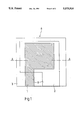
- FIG. 1 shows a humidity sensor in accordance with the invention in a sectional top view.
- FIG. 2 shows a sectional side view of the capacitive humidity sensor illustrated in FIG. 1 taken along section A--A.
- FIG. 3 shows the capacitive humidity sensor illustrated in FIG. 1 in a sectional side view after coating of the conductive layer with a dielectric layer.
- a sensor 6 can be fabricated onto, for instance, a lass substrate 4 so that a first conductive electrode 1, which can be an anodically oxidized tantalum layer for instance, is first placed closest to the substrate 4.
- the first conductive electrode 1 is coated with a layer 3 of dielectric material, which typically is a suitable polymer such as cellulose acetate butyrate for instance.
- the dielectric layer 3 is covered by a second conductive electrode 2 from chromium for instance or other suitable material having a high resistance to wear.
- the second conductive electrode 2 must be of such a material that self-contracts under internal stresses when produced as a thin layer. This approach produces a plurality of clefts 7 in the second electrode 2.
- the contact leads (not shown) of a measurement device of dielectric factor are connected to electrodes 1 and 2 of the sensor at contact areas 8.
- the second conductive electrode 2 of the sensor can be coated by a second dielectric layer 5 through which water vapour can diffuse to reach the first dielectric layer 3.
- Suitable materials for the second dielectric layer are, for instance, cellulose acetate and cross-linked polyvinyl pyrrolidone.
- the preferred embodiment of the invention is characterized by a strong adherence of the second dielectric layer 5 to both the conductive electrode 2 with the clefts 7 and the first dielectric layer 3.
- the sensor in accordance with the invention can be fabricated as follows:
- the first electrode 1 is fabricated onto a glass substrate 4 using the methods of conventional thin-film technology, for instance, anodic oxidation.
- a polymer layer 3 is produced onto the first electrode 1 by, for instance, lifting the glass substrate 4 slowly from a liquid polymer, whereby a thin layer of plastic dissolved in the solvent remains on the glass substrate 4.
- the solvent of the dielectric material can be, for instance, a mixture of NMP (N-methylpyrrolidone) and alcohol, wherein the NMP solvent forms the slowly evaporating component and the polymer is cellulose acetate butyrate.
- the polymer is predried for approx. 10 minutes at 150° C. temperature.
- the alcohol is thereby evaporated, but the polymer remains in a plasticized state by the effect of the NMP plasticizer.
- a surface electrode 2 is deposited of, for instance, chromium onto the plasticized polymer layer.
- the electrode 2 is deposited up to approx. 0.1 . . . 1 ⁇ m thickness
- the sensor structure is postbaked for approx. 3 days at 150° C. temperature, whereby the NMP plasticizer is evaporated and the dielectric layer polymerizes to its final hardness.
- the use of slowly evaporating solvent as plasticizing means of the dielectric layer can be omitted by maintaining the dielectric layer in a plastic state by means of elevated process temperature, whereby the sensor must be held, for instance, at 180° C. during the vapour deposition of the surface electrode 2.
- An essential condition is that the substrate temperature is above the glass transition temperature T g or the melting temperature.
- the second dielectric layer 5 is produced by immersion into liquid plastic using a comparable method with that used for the first layer 3.
- An essential condition is that the solvent used in the liquid polymer does not dissolve the first layer 3.
- the second dielectric layer can be produced by plasma polymerization from a suitable monomer (e.g., styrene), whereby a good adhesion between the layers is achieved.
Abstract
Description
r.sub.k =(2γM)/(rRT 1n(P.sub.s /P)),
Claims (8)
Applications Claiming Priority (2)
| Application Number | Priority Date | Filing Date | Title |
|---|---|---|---|
| FI893797A FI84862C (en) | 1989-08-11 | 1989-08-11 | Capacitive humidifier construction and method of making it |
| FI893797 | 1989-08-11 |
Publications (1)
| Publication Number | Publication Date |
|---|---|
| US5075816A true US5075816A (en) | 1991-12-24 |
Family
ID=8528837
Family Applications (1)
| Application Number | Title | Priority Date | Filing Date |
|---|---|---|---|
| US07/553,596 Expired - Lifetime US5075816A (en) | 1989-08-11 | 1990-07-18 | Capacitive humidity sensor construction and method for manufacturing the sensor |
Country Status (6)
| Country | Link |
|---|---|
| US (1) | US5075816A (en) |
| JP (1) | JP2938531B2 (en) |
| DE (1) | DE4023778C2 (en) |
| FI (1) | FI84862C (en) |
| FR (1) | FR2650892B1 (en) |
| GB (1) | GB2234820B (en) |
Cited By (24)
| Publication number | Priority date | Publication date | Assignee | Title |
|---|---|---|---|---|
| US6452776B1 (en) * | 2000-04-06 | 2002-09-17 | Intel Corporation | Capacitor with defect isolation and bypass |
| US20030010119A1 (en) * | 2001-07-16 | 2003-01-16 | Inao Toyoda | Capacitive Humidity Sensor |
| US6724612B2 (en) | 2002-07-09 | 2004-04-20 | Honeywell International Inc. | Relative humidity sensor with integrated signal conditioning |
| DE10338277A1 (en) * | 2003-08-20 | 2005-03-17 | Siemens Ag | Organic capacitor with voltage controlled capacity |
| US20060125061A1 (en) * | 2003-01-09 | 2006-06-15 | Wolfgang Clemens | Board or substrate for an organic electronic device and use thereof |
| WO2006078105A1 (en) * | 2005-01-19 | 2006-07-27 | Rechner Korea Co., Ltd | Capacitance type leakage sensor |
| US20070008019A1 (en) * | 2003-09-03 | 2007-01-11 | Wolfgang Clemens | Mechanical control elements for organic polymer electronic devices |
| US20070017401A1 (en) * | 2003-09-03 | 2007-01-25 | Polyic Gmbh & Co. Kg | Polymer mixtures for printed polymer electronic circuits |
| US7479670B2 (en) | 2003-08-25 | 2009-01-20 | Polyic Gmbh & Co Kg | Organic electronic component with high resolution structuring, and method of the production thereof |
| US20090189147A1 (en) * | 2004-01-14 | 2009-07-30 | Walter Fix | Organic transistor comprising a self-aligning gate electrode, and method for the production thereof |
| US7589553B2 (en) | 2005-03-01 | 2009-09-15 | Polyic Gmbh & Co. Kg | Electronic module with organic logic circuit elements |
| US7724550B2 (en) | 2004-12-23 | 2010-05-25 | Polyic Gmbh & Co. Kg | Organic rectifier |
| US7812343B2 (en) | 2005-04-15 | 2010-10-12 | Polyic Gmbh & Co. Kg | Multilayer composite body having an electronic function |
| US7843342B2 (en) | 2005-03-01 | 2010-11-30 | Polyic Gmbh & Co. Kg | Organic clock generator |
| US7847695B2 (en) | 2004-08-23 | 2010-12-07 | Polyic Gmbh & Co. Kg | External package capable of being radio-tagged |
| US7846838B2 (en) | 2005-07-29 | 2010-12-07 | Polyic Gmbh & Co. Kg | Method for producing an electronic component |
| US7940159B2 (en) | 2004-12-10 | 2011-05-10 | Polyic Gmbh & Co. Kg | Identification system |
| US7940340B2 (en) | 2005-07-04 | 2011-05-10 | Polyic Gmbh & Co. Kg | Multilayer body with electrically controllable optically active systems of layers |
| US20120228109A1 (en) * | 2011-03-08 | 2012-09-13 | Ibiden Co., Ltd. | Sensor, keyboard and method for manufacturing sensor |
| US8315061B2 (en) | 2005-09-16 | 2012-11-20 | Polyic Gmbh & Co. Kg | Electronic circuit with elongated strip layer and method for the manufacture of the same |
| AU2013204540A1 (en) * | 2013-03-12 | 2014-10-02 | Warner, Shane Charles MR | Detecting moisture and/or termites. |
| CN105502282A (en) * | 2015-11-30 | 2016-04-20 | 上海集成电路研发中心有限公司 | Method for manufacturing MEMS humidity sensor |
| CN109690302A (en) * | 2016-09-30 | 2019-04-26 | 三美电机株式会社 | Humidity sensor |
| US11435310B2 (en) * | 2017-03-31 | 2022-09-06 | Mitsumi Electric Co., Ltd. | Humidity sensor |
Families Citing this family (5)
| Publication number | Priority date | Publication date | Assignee | Title |
|---|---|---|---|---|
| FI92439C (en) * | 1993-09-29 | 1994-11-10 | Vaisala Oy | Electric impedance sensor for measuring physical quantities, especially temperature or humidity and method for producing the sensor in question |
| FI98567C (en) * | 1993-09-29 | 1997-07-10 | Vaisala Oy | Impedance sensor, especially for radio probe use, as well as a method for producing a sensor |
| JP4860793B2 (en) * | 2005-05-19 | 2012-01-25 | 株式会社日本自動車部品総合研究所 | Manufacturing method of humidity sensor |
| DE102011086479A1 (en) * | 2011-11-16 | 2013-05-16 | Robert Bosch Gmbh | Integrated humidity sensor and method for its production |
| JP2020047776A (en) * | 2018-09-19 | 2020-03-26 | 国立研究開発法人産業技術総合研究所 | Gas-permeable capacitor element, sensor element, and measurement method using them |
Citations (4)
| Publication number | Priority date | Publication date | Assignee | Title |
|---|---|---|---|---|
| US3614561A (en) * | 1968-06-25 | 1971-10-19 | Siemens Ag | Electrical condenser |
| US4164868A (en) * | 1972-10-12 | 1979-08-21 | Vaisala Oy | Capacitive humidity transducer |
| US4305112A (en) * | 1978-11-06 | 1981-12-08 | Siemens Aktiengesellschaft | Capacitance humidity sensing element |
| US4761710A (en) * | 1987-06-23 | 1988-08-02 | Industrial Technology Research Institute | Polyimide capacitive humidity sensing element |
Family Cites Families (8)
| Publication number | Priority date | Publication date | Assignee | Title |
|---|---|---|---|---|
| FR1264142A (en) * | 1959-06-23 | 1961-06-19 | element sensitive to humidity, usable in a hygrometer | |
| US3574681A (en) * | 1966-03-31 | 1971-04-13 | Texas Instruments Inc | Aluminum oxide humidity sensor |
| FR2142573B1 (en) * | 1971-06-21 | 1973-05-25 | Commissariat Energie Atomique | |
| US4156268A (en) * | 1977-08-29 | 1979-05-22 | Longwood Machine Works, Inc. | Humidity sensing element and method of manufacture thereof |
| FR2486656A1 (en) * | 1980-07-09 | 1982-01-15 | Commissariat Energie Atomique | CAPACITIVE HYGROMETER |
| FR2498329A1 (en) * | 1981-01-19 | 1982-07-23 | Commissariat Energie Atomique | THIN DIELECTRIC CAPACITIVE HYGROMETER AND METHOD OF MANUFACTURING THE SAME |
| FI65674C (en) * | 1982-12-21 | 1984-06-11 | Vaisala Oy | CAPACITIVE FUEL FARTIGHETSGIVARE OCH FOERFARANDE FOER FRAMSTAELLNINGDAERAV |
| NL8803223A (en) * | 1988-12-30 | 1990-07-16 | Flucon Bv | CAPACITIVE MOISTURE SENSOR. |
-
1989
- 1989-08-11 FI FI893797A patent/FI84862C/en active IP Right Grant
-
1990
- 1990-07-18 US US07/553,596 patent/US5075816A/en not_active Expired - Lifetime
- 1990-07-26 DE DE4023778A patent/DE4023778C2/en not_active Expired - Lifetime
- 1990-08-03 GB GB9017034A patent/GB2234820B/en not_active Expired - Lifetime
- 1990-08-08 FR FR909010121A patent/FR2650892B1/en not_active Expired - Lifetime
- 1990-08-09 JP JP2213587A patent/JP2938531B2/en not_active Expired - Lifetime
Patent Citations (4)
| Publication number | Priority date | Publication date | Assignee | Title |
|---|---|---|---|---|
| US3614561A (en) * | 1968-06-25 | 1971-10-19 | Siemens Ag | Electrical condenser |
| US4164868A (en) * | 1972-10-12 | 1979-08-21 | Vaisala Oy | Capacitive humidity transducer |
| US4305112A (en) * | 1978-11-06 | 1981-12-08 | Siemens Aktiengesellschaft | Capacitance humidity sensing element |
| US4761710A (en) * | 1987-06-23 | 1988-08-02 | Industrial Technology Research Institute | Polyimide capacitive humidity sensing element |
Cited By (31)
| Publication number | Priority date | Publication date | Assignee | Title |
|---|---|---|---|---|
| US6452776B1 (en) * | 2000-04-06 | 2002-09-17 | Intel Corporation | Capacitor with defect isolation and bypass |
| US20030010119A1 (en) * | 2001-07-16 | 2003-01-16 | Inao Toyoda | Capacitive Humidity Sensor |
| US6647782B2 (en) * | 2001-07-16 | 2003-11-18 | Denso Corporation | Capacitive humidity sensor |
| US6724612B2 (en) | 2002-07-09 | 2004-04-20 | Honeywell International Inc. | Relative humidity sensor with integrated signal conditioning |
| US20060125061A1 (en) * | 2003-01-09 | 2006-06-15 | Wolfgang Clemens | Board or substrate for an organic electronic device and use thereof |
| US20070030623A1 (en) * | 2003-08-20 | 2007-02-08 | Polyic Gmbh & Co. Kg | Organic capacitor having a voltage-controlled capacitance |
| DE10338277A1 (en) * | 2003-08-20 | 2005-03-17 | Siemens Ag | Organic capacitor with voltage controlled capacity |
| US7479670B2 (en) | 2003-08-25 | 2009-01-20 | Polyic Gmbh & Co Kg | Organic electronic component with high resolution structuring, and method of the production thereof |
| US7678857B2 (en) | 2003-09-03 | 2010-03-16 | Polyic Gmbh & Co. Kg | Polymer mixtures for printed polymer electronic circuits |
| US20070008019A1 (en) * | 2003-09-03 | 2007-01-11 | Wolfgang Clemens | Mechanical control elements for organic polymer electronic devices |
| US7576294B2 (en) | 2003-09-03 | 2009-08-18 | Polyic Gmbh & Co. Kg | Mechanical control elements for organic polymer electronic devices |
| US20070017401A1 (en) * | 2003-09-03 | 2007-01-25 | Polyic Gmbh & Co. Kg | Polymer mixtures for printed polymer electronic circuits |
| US20090189147A1 (en) * | 2004-01-14 | 2009-07-30 | Walter Fix | Organic transistor comprising a self-aligning gate electrode, and method for the production thereof |
| US7847695B2 (en) | 2004-08-23 | 2010-12-07 | Polyic Gmbh & Co. Kg | External package capable of being radio-tagged |
| US7940159B2 (en) | 2004-12-10 | 2011-05-10 | Polyic Gmbh & Co. Kg | Identification system |
| US7724550B2 (en) | 2004-12-23 | 2010-05-25 | Polyic Gmbh & Co. Kg | Organic rectifier |
| WO2006078105A1 (en) * | 2005-01-19 | 2006-07-27 | Rechner Korea Co., Ltd | Capacitance type leakage sensor |
| US7589553B2 (en) | 2005-03-01 | 2009-09-15 | Polyic Gmbh & Co. Kg | Electronic module with organic logic circuit elements |
| US7843342B2 (en) | 2005-03-01 | 2010-11-30 | Polyic Gmbh & Co. Kg | Organic clock generator |
| US7812343B2 (en) | 2005-04-15 | 2010-10-12 | Polyic Gmbh & Co. Kg | Multilayer composite body having an electronic function |
| US7940340B2 (en) | 2005-07-04 | 2011-05-10 | Polyic Gmbh & Co. Kg | Multilayer body with electrically controllable optically active systems of layers |
| US7846838B2 (en) | 2005-07-29 | 2010-12-07 | Polyic Gmbh & Co. Kg | Method for producing an electronic component |
| US8315061B2 (en) | 2005-09-16 | 2012-11-20 | Polyic Gmbh & Co. Kg | Electronic circuit with elongated strip layer and method for the manufacture of the same |
| US20120228109A1 (en) * | 2011-03-08 | 2012-09-13 | Ibiden Co., Ltd. | Sensor, keyboard and method for manufacturing sensor |
| AU2013204540A1 (en) * | 2013-03-12 | 2014-10-02 | Warner, Shane Charles MR | Detecting moisture and/or termites. |
| CN105502282A (en) * | 2015-11-30 | 2016-04-20 | 上海集成电路研发中心有限公司 | Method for manufacturing MEMS humidity sensor |
| CN109690302A (en) * | 2016-09-30 | 2019-04-26 | 三美电机株式会社 | Humidity sensor |
| EP3502680A4 (en) * | 2016-09-30 | 2019-09-11 | Minebea Mitsumi Inc. | Humidity sensor |
| US10948448B2 (en) | 2016-09-30 | 2021-03-16 | Minebea Mitsumi Inc. | Humidity sensor |
| CN109690302B (en) * | 2016-09-30 | 2022-07-19 | 美蓓亚三美株式会社 | Humidity sensor |
| US11435310B2 (en) * | 2017-03-31 | 2022-09-06 | Mitsumi Electric Co., Ltd. | Humidity sensor |
Also Published As
| Publication number | Publication date |
|---|---|
| DE4023778A1 (en) | 1991-02-14 |
| JP2938531B2 (en) | 1999-08-23 |
| DE4023778C2 (en) | 2003-08-21 |
| FR2650892B1 (en) | 1992-12-11 |
| FI893797A0 (en) | 1989-08-11 |
| GB2234820B (en) | 1994-06-22 |
| FI84862B (en) | 1991-10-15 |
| FI84862C (en) | 1992-01-27 |
| FR2650892A1 (en) | 1991-02-15 |
| JPH0387642A (en) | 1991-04-12 |
| GB9017034D0 (en) | 1990-09-19 |
| FI893797A (en) | 1991-02-12 |
| GB2234820A (en) | 1991-02-13 |
Similar Documents
| Publication | Publication Date | Title |
|---|---|---|
| US5075816A (en) | Capacitive humidity sensor construction and method for manufacturing the sensor | |
| US4532016A (en) | Capacitive hygrometer and its production process | |
| US4482581A (en) | Process for the production of a capacitive hygrometer | |
| US4305112A (en) | Capacitance humidity sensing element | |
| US6450026B1 (en) | Capacitive sensors for measuring humidity and method of making same | |
| JPH0675052B2 (en) | Capacitance type humidity sensor | |
| US4651121A (en) | Moisture sensor and a method for the production of the same | |
| US5471723A (en) | Methods of manufacturing thin-film absolute pressure sensors | |
| KR101316128B1 (en) | Humidity sensor | |
| EP0395349B1 (en) | Moisture sensitive element | |
| GB2149922A (en) | Capacitive moisture sensor and process for producing same | |
| EP0472398B1 (en) | Electrode for measuring pH and method for manufacturing the same | |
| JPH03167464A (en) | Humidity-sensitive element and its manufacture | |
| KR100987852B1 (en) | Solid electrolytic capacitor | |
| FI111034B (en) | Moisture sensitive element and process for its preparation | |
| JP2003188052A (en) | Solid electrolytic capacitor element and manufacturing method thereof, and solid electrolytic capacitor | |
| CA2130505C (en) | Thin-film absolute pressure sensors and methods of manufacturing the same | |
| DE19917717C2 (en) | Capacitive humidity sensor | |
| US4765870A (en) | Method of manufacture of an electric moisture-content sensor | |
| US5087480A (en) | Method for manufacturing a moisture permeable electrode in a moisture sensor | |
| KR100727674B1 (en) | Methodo of manufacturing a high-precise capacitive humidity sensor | |
| JPS63163265A (en) | Moisture sensitive element and its production | |
| JP3006191B2 (en) | Method for producing metallized film for capacitor | |
| JP2810779B2 (en) | Capacitive thin film humidity sensor and method of manufacturing the same | |
| FI113806B (en) | Moisture detection elements and method for making them |
Legal Events
| Date | Code | Title | Description |
|---|---|---|---|
| AS | Assignment |
Owner name: VAISALA OY,, FINLAND Free format text: ASSIGNMENT OF ASSIGNORS INTEREST.;ASSIGNOR:STORMBOM, LARS;REEL/FRAME:005374/0622 Effective date: 19900228 |
|
| STCF | Information on status: patent grant |
Free format text: PATENTED CASE |
|
| FEPP | Fee payment procedure |
Free format text: PAYOR NUMBER ASSIGNED (ORIGINAL EVENT CODE: ASPN); ENTITY STATUS OF PATENT OWNER: LARGE ENTITY |
|
| FPAY | Fee payment |
Year of fee payment: 4 |
|
| FPAY | Fee payment |
Year of fee payment: 8 |
|
| FEPP | Fee payment procedure |
Free format text: PAYER NUMBER DE-ASSIGNED (ORIGINAL EVENT CODE: RMPN); ENTITY STATUS OF PATENT OWNER: LARGE ENTITY Free format text: PAYOR NUMBER ASSIGNED (ORIGINAL EVENT CODE: ASPN); ENTITY STATUS OF PATENT OWNER: LARGE ENTITY |
|
| FPAY | Fee payment |
Year of fee payment: 12 |
|
| REMI | Maintenance fee reminder mailed |