US5073720A - Liquid level and volume measurement device - Google Patents
Liquid level and volume measurement device Download PDFInfo
- Publication number
- US5073720A US5073720A US07/561,413 US56141390A US5073720A US 5073720 A US5073720 A US 5073720A US 56141390 A US56141390 A US 56141390A US 5073720 A US5073720 A US 5073720A
- Authority
- US
- United States
- Prior art keywords
- fluid
- optical
- liquid level
- volume
- light
- Prior art date
- Legal status (The legal status is an assumption and is not a legal conclusion. Google has not performed a legal analysis and makes no representation as to the accuracy of the status listed.)
- Expired - Fee Related
Links
- 239000007788 liquid Substances 0.000 title claims abstract description 84
- 238000005259 measurement Methods 0.000 title claims abstract description 34
- 230000003287 optical effect Effects 0.000 claims abstract description 84
- 239000012530 fluid Substances 0.000 claims abstract description 44
- 238000000034 method Methods 0.000 claims description 11
- 239000013307 optical fiber Substances 0.000 claims description 8
- 238000012360 testing method Methods 0.000 claims description 5
- XLYOFNOQVPJJNP-UHFFFAOYSA-N water Substances O XLYOFNOQVPJJNP-UHFFFAOYSA-N 0.000 claims description 5
- 230000003595 spectral effect Effects 0.000 claims description 4
- 238000001514 detection method Methods 0.000 description 8
- 238000013459 approach Methods 0.000 description 6
- 238000013461 design Methods 0.000 description 6
- 230000008859 change Effects 0.000 description 3
- 239000000835 fiber Substances 0.000 description 3
- 238000010586 diagram Methods 0.000 description 2
- 238000010521 absorption reaction Methods 0.000 description 1
- 238000006243 chemical reaction Methods 0.000 description 1
- 230000002596 correlated effect Effects 0.000 description 1
- 230000000875 corresponding effect Effects 0.000 description 1
- 230000008878 coupling Effects 0.000 description 1
- 238000010168 coupling process Methods 0.000 description 1
- 238000005859 coupling reaction Methods 0.000 description 1
- 230000003247 decreasing effect Effects 0.000 description 1
- 230000001419 dependent effect Effects 0.000 description 1
- 238000007689 inspection Methods 0.000 description 1
- 238000012986 modification Methods 0.000 description 1
- 230000004048 modification Effects 0.000 description 1
- 230000008569 process Effects 0.000 description 1
- 238000003908 quality control method Methods 0.000 description 1
- 241000894007 species Species 0.000 description 1
- 230000001360 synchronised effect Effects 0.000 description 1
Images
Classifications
-
- G—PHYSICS
- G01—MEASURING; TESTING
- G01F—MEASURING VOLUME, VOLUME FLOW, MASS FLOW OR LIQUID LEVEL; METERING BY VOLUME
- G01F23/00—Indicating or measuring liquid level or level of fluent solid material, e.g. indicating in terms of volume or indicating by means of an alarm
- G01F23/22—Indicating or measuring liquid level or level of fluent solid material, e.g. indicating in terms of volume or indicating by means of an alarm by measuring physical variables, other than linear dimensions, pressure or weight, dependent on the level to be measured, e.g. by difference of heat transfer of steam or water
- G01F23/28—Indicating or measuring liquid level or level of fluent solid material, e.g. indicating in terms of volume or indicating by means of an alarm by measuring physical variables, other than linear dimensions, pressure or weight, dependent on the level to be measured, e.g. by difference of heat transfer of steam or water by measuring the variations of parameters of electromagnetic or acoustic waves applied directly to the liquid or fluent solid material
- G01F23/284—Electromagnetic waves
- G01F23/292—Light, e.g. infrared or ultraviolet
Definitions
- This invention relates generally to a device for measuring liquid level or volume of a contained fluid.
- a liquid level and volume measurement device has been designed and constructed which accurately measures fluid levels and volumes of transparent or semitransparent liquids.
- This method is applicable in the medical industry in measuring liquid volumes in test tubes and beakers or any other application where the liquid container is or can be transparent.
- the method can be incorporated into automated container filling equipment or into automated quality control/inspection systems.
- the liquid levels or volumes that are measurable can vary widely.
- the accuracy of the method can be adjusted by choosing a wavelength of operation which is matched to the liquid level to be measured and the optical attenuation coefficient of the liquid.
- This liquid level measurement device utilizes a light source and detector to measure the optical attenuation, and hence, the liquid level of a liquid.
- the light source may be coupled into an optical fiber and located remotely from the measurement area.
- the light source may be lensed or may directly transmit light into the fiber or liquid to be measured.
- the detector may be arranged in a similar manner; being bare, lensed or coupled to an optical fiber.
- the optical source has associated drive circuitry to produce either a continuous wave (CW) or a modulated signal.
- the optical detector also has associated circuitry to measure the output voltage of the detector and convert the voltage to liquid level or volume.
- a lock-in amplifier may be used to measure the detector voltage.
- a computer may be used to convert the detector voltage to liquid level or volume.
- the optical source can consist of a lamp with an output at the desired wavelength with appropriate filters or monochrometer or may be an LED or laser diode.
- Lenses may be used to optimize the coupling of the optical source to a fiber and of a fiber to the optical detector. Lenses may also be used to collimate the optical beam passing through the liquid.
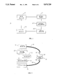
- FIG. 1 is a functional block diagram of the liquid level and volume measurement device.
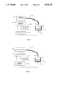
- FIG. 2 is one embodiment of the device of FIG. 1 showing placement of optics.
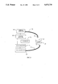
- FIG. 3 is an illustration of the liquid level and volume measurement device of FIG. 1 comprising an optical source integral with a vessel.
- FIG. 4 is an illustration of the liquid level and volume measurement device of FIG. 1 comprising an optical detector integral with the fluid vessel.
- FIG. 5 is an illustration of the liquid level and volume measurement device of FIG. 1 showing an alternate placement of optics.
- FIG. 1 a block diagram of one embodiment of the liquid level and volume measurement device may be viewed.
- the invention 10 may be understood as comprising a drive circuit 11, an optical source 12, an optical subassembly 13, an optical detector 14 and analysis circuitry 15.
- the drive circuitry 11 for the optical source maintains the average optical power emitted by the source at a constant value over long periods of time.
- This circuitry may modulate the optical source or may provide a drive current to the optical source so that the optical source operates in a CW fashion.
- the most sensitive embodiment of the invention is for the drive circuitry to modulate the optical source so that synchronous detection techniques can be used at the optical detector.
- the drive circuitry is composed of standard electrical components and embodies techniques and circuitry known to those skilled in the art. The exact circuitry is a design choice of the electronics technician. Any circuitry that appropriately stimulates the optical source with a controlled input compatible with the optical choice and detection scheme will be acceptable.
- the drive circuitry could be as simple as a constant voltage source such as a battery. In other embodiments of the invention, the drive circuitry would be required to provide constant drive current and might contain a power feedback circuit.
- the optical source 12 selected will dictate the parameters of the drive circuitry.
- the optical source 12 may be either a white light source with appropriate filters or a monochrometer, an LED or a laser diode.
- the function of the optical source is to emit a constant level of optical power within a specific wavelength band.
- the optical source 12 is chosen and/or the wavelength controlled to match the spectral properties of the fluid to be measured. Should the fluid be water based, a wavelength would be selected at or near 1300 nanometers in an effort to match the absorptive characteristics of the fluid.
- Commercially available monochrometers, LED's, and lasers are all available to match the absorption characteristics of most fluids, including the 1300 nanometers required for water based fluid measurements.
- the optical subassembly -3 may be constructed by an electronics technician using off-the-shelf commercial components. This subassembly simply directs the light emitted by the optical source 12 through the fluid to be measured onto the optical detector 14.
- Optical subassembly 13 can simply be the air between the optical source 12 and the optical detector 14 in the most simple embodiments, or can be a set of discrete or integrated optical components. The exact configuration will be a design choice corresponding to the application and requirements of other system components.
- the optical detector converts the optical energy received from the source to a voltage or current as required by analysis circuitry 15. Standard commercially available detector components are widely available to accommodate the design choices of the technician.
- the analysis circuitry 15 is composed of standard off-the-shelf components and may be constructed as part of the system design. Functionally, the analysis circuitry 15 processes the detector output to determine the attenuation of the optical light beam due to the fluid under test. The attenuation is then correlated to the liquid level or volume of the fluid.
- FIG. 2 a preferred embodiment of the liquid level and volume measurement device showing a vessel 20 which will contain the fluid to be measured.
- the optical subassembly chosen for illustration in FIG. 2 consists of a source optical fiber 31, a launch lens 32, a detection lens 33, and a detection optical fiber 34.
- Light is launched from the optical source into the source optical fiber where it is guided to the launch lens.
- the launch lens At the launch lens the light is collimated and launched through the liquid being measured onto the detection lens.
- the detection lens focuses the light into the detection optical fiber which guides the light to the optical detector.
- the optical subassembly may contain other lenses, mirrors, or other optical elements depending upon the application and the physical requirements of the application.
- the function of the optical detector 14 is to convert the optical power incident upon it to an output voltage.
- the output voltage of the optical detector 14 will be given by:
- the optical detector may be a PIN diode or any other device suitable for the intended application.
- the function of the analysis circuitry is to convert the detector output to a liquid level or volume.
- the embodiment of FIG. 2 employs a detector outputting a voltage as a design choice and the analysis circuitry 15 is constructed accordingly.
- a processor 51 is employed in FIG. 2 as part of the analysis circuitry used to perform the conversion of the detector output to a liquid level or volume as described below. Any commercial processor can be deployed as required by system design parameters or, in its most simple embodiment, a power meter and manual calculations could be used.
- the analysis circuitry illustrated in FIG. 2 includes a locking amplifier 52 so that background light level changes around the liquid level and volume measurement device do not introduce errors into the measurement.
- Lock-in amplifiers are standard off-the-shelf components and the techniques of their use is widely known to persons of ordinary skill in the electronics and optical arts.
- Attenuation (A) is defined as ##EQU2## where P a and P b are two different power levels, and the inserted liquid is the only change to the setup between the two power measurements, then the attenuation of the liquid is given by ##EQU3##
- ⁇ is the attenuation coefficient of the liquid and x is the thickness of the liquid.
- the attenuation of the liquid is then also given by ##EQU4##
- the thickness of the liquid is, therefore, directly proportional to the attenuation of the liquid.
- the volume of the liquid can be determined from the level (thickness) of the liquid and the dimensions of the container.
- FIG. 3 illustrates another embodiment of the invention wherein the optical source is an integral part of the vessel 20 containing the fluid.
- Embodiments of this specie may either incorporate the entire optical source as an integral part of the fluid vessel or simply embed the launch lens therein and connect the launch lens to the optical source with an optical fiber such as is illustrated in FIG. 2.
- the embodiment integrating the optical source or the launch lens of the optical source may not be the preferred 13 embodiment in applications where it is desired to avoid contact with the vessel containing the fluid to be tested. By integrating part or all of the optical source in the vessel one loses the ability to easily interchange vessels.
- FIG. 4 is a further embodiment illustrating a version wherein the detector is an integral part of the vessel. This embodiment would share the shortcomings described above for FIG. 3.
- optical light beam is substantially vertical in respect to the fluid under test or the beam could bisect the fluid on a diagonal as shown in FIG. 5.
Abstract
The liquid level measurement device is an electro-optical device which uses light source (typically a light emitting diode (LED) or laser diode) and an optical detector to measure the level of a liquid in a container. The light beam is passed through the liquid and received by the optical detector. The detector output is processed to determine the liquid level or the liquid volume. A special feature is the ability to measure a continuum of fluid levels or volumes.
Description
The invention described herein was made in the performance of official duties by an employee of the Department of the Navy and may be manufactured, used, licensed by or for the Government for any governmental purpose without payment of any royalties thereon.
(1) Field of the Invention
This invention relates generally to a device for measuring liquid level or volume of a contained fluid.
(2) Description of the Prior Art
The prior art of liquid level sensing can be divided into two categories: discrete sensing devices that sense whether a liquid level is above or below a certain point, or distributed sensing devices which transmit varying amounts of light depending upon the liquid level.
Scifres U.S. Pat. No. 4,287,427, filed Jan. 2, 1980 is an example of the latter. In this reference the attenuation of a light guide is changed depending upon the surface area of the light guide contacted by the liquid being measured. The principle used is the difference in the index of refraction between air and the liquid being measured. This approach inherently requires contact with the liquid being measured and cannot be used in case where contact is not allowed. This approach engenders liquid droplets which cling onto the sensor above the actual liquid level and distort the reading. These droplets may be formed from the liquid level being decreased from one level to a lower level.
Other types of sensing devices are essentially on/off sensors and do not allow measurement of liquid level as a continuous quantity (Hansel et al. U.S. Pat. No. 4,069,838, filed Jan. 24, 1978 is an example). These approaches use the local attenuation of light between a source and a detector to tell when the liquid has reached a particular level, or a change in the path of the light beam due to the liquid level which is sensed by the detector as a change in detected light. The Hansel et al. reference uses the attenuation approach. This method can only tell when the liquid level is above a certain point. It cannot give a continuous measurement of the liquid level. Furthermore, it requires contact with the measured liquid. Not all devices of this type require contact, such as Shapiro U.S. Pat. No. 3,741,656, filed June 26, 1973. All methods do suffer from the fact that they cannot give a continuous measurement over the full liquid level range. This is addressed by reference Kind U.S. Pat. No. 3,713,338, filed Nov. 30, 1973 by using multiple single level sensing devices to obtain a somewhat continuous measurement of the liquid level. This approach does require multiple sensors and has limited accuracy dependent upon the number of discrete sensing devices used. Additionally, the Kind reference requires contact with the measured liquid, although this method could be implemented without contact. This approach is one requiring complex hardware.
All prior art located either provides a non-contact measurement or a continuously variable measurement, but not both at the same time. In addition, no prior art reference is known teaching a non-contact measurement device that has a high degree of accuracy over a broad range.
Accordingly, it is an object of the present invention to provide a liquid level and volume measurement device with an extended measurement range.
It is a further object to teach a device that measures liquid levels and volume over a broad range with a high degree of accuracy.
It is still another object of the instant invention to teach a device having the capability of accurate liquid level and volume measurement without the necessity of contact with the fluid under test or the vessel containing the fluid.
Other objects and advantages of the present invention will become more apparent hereinafter in the specifications and drawings.
In accordance with the present invention, a liquid level and volume measurement device has been designed and constructed which accurately measures fluid levels and volumes of transparent or semitransparent liquids. This method is applicable in the medical industry in measuring liquid volumes in test tubes and beakers or any other application where the liquid container is or can be transparent. The method can be incorporated into automated container filling equipment or into automated quality control/inspection systems. The liquid levels or volumes that are measurable can vary widely. The accuracy of the method can be adjusted by choosing a wavelength of operation which is matched to the liquid level to be measured and the optical attenuation coefficient of the liquid.
This liquid level measurement device utilizes a light source and detector to measure the optical attenuation, and hence, the liquid level of a liquid. The light source may be coupled into an optical fiber and located remotely from the measurement area. The light source may be lensed or may directly transmit light into the fiber or liquid to be measured. The detector may be arranged in a similar manner; being bare, lensed or coupled to an optical fiber. The optical source has associated drive circuitry to produce either a continuous wave (CW) or a modulated signal. The optical detector also has associated circuitry to measure the output voltage of the detector and convert the voltage to liquid level or volume. A lock-in amplifier may be used to measure the detector voltage. A computer may be used to convert the detector voltage to liquid level or volume. The optical source can consist of a lamp with an output at the desired wavelength with appropriate filters or monochrometer or may be an LED or laser diode. Lenses may be used to optimize the coupling of the optical source to a fiber and of a fiber to the optical detector. Lenses may also be used to collimate the optical beam passing through the liquid.
The device may be more clearly understood when turning to the following drawings wherein like elements are consistently numbered throughout the different views and representations.
FIG. 1 is a functional block diagram of the liquid level and volume measurement device.
FIG. 2 is one embodiment of the device of FIG. 1 showing placement of optics.
FIG. 3 is an illustration of the liquid level and volume measurement device of FIG. 1 comprising an optical source integral with a vessel.
FIG. 4 is an illustration of the liquid level and volume measurement device of FIG. 1 comprising an optical detector integral with the fluid vessel.
FIG. 5 is an illustration of the liquid level and volume measurement device of FIG. 1 showing an alternate placement of optics.
Turning now to FIG. 1, a block diagram of one embodiment of the liquid level and volume measurement device may be viewed. Therein, the invention 10 may be understood as comprising a drive circuit 11, an optical source 12, an optical subassembly 13, an optical detector 14 and analysis circuitry 15.
The drive circuitry 11 for the optical source maintains the average optical power emitted by the source at a constant value over long periods of time. This circuitry may modulate the optical source or may provide a drive current to the optical source so that the optical source operates in a CW fashion. The most sensitive embodiment of the invention is for the drive circuitry to modulate the optical source so that synchronous detection techniques can be used at the optical detector. The drive circuitry is composed of standard electrical components and embodies techniques and circuitry known to those skilled in the art. The exact circuitry is a design choice of the electronics technician. Any circuitry that appropriately stimulates the optical source with a controlled input compatible with the optical choice and detection scheme will be acceptable. Depending upon the optical source and detection parameters, the drive circuitry could be as simple as a constant voltage source such as a battery. In other embodiments of the invention, the drive circuitry would be required to provide constant drive current and might contain a power feedback circuit.
The optical source 12 selected will dictate the parameters of the drive circuitry. The optical source 12 may be either a white light source with appropriate filters or a monochrometer, an LED or a laser diode. The function of the optical source is to emit a constant level of optical power within a specific wavelength band. The optical source 12 is chosen and/or the wavelength controlled to match the spectral properties of the fluid to be measured. Should the fluid be water based, a wavelength would be selected at or near 1300 nanometers in an effort to match the absorptive characteristics of the fluid. Commercially available monochrometers, LED's, and lasers are all available to match the absorption characteristics of most fluids, including the 1300 nanometers required for water based fluid measurements.
Likewise, the optical subassembly -3 may be constructed by an electronics technician using off-the-shelf commercial components. This subassembly simply directs the light emitted by the optical source 12 through the fluid to be measured onto the optical detector 14. Optical subassembly 13 can simply be the air between the optical source 12 and the optical detector 14 in the most simple embodiments, or can be a set of discrete or integrated optical components. The exact configuration will be a design choice corresponding to the application and requirements of other system components.
The optical detector converts the optical energy received from the source to a voltage or current as required by analysis circuitry 15. Standard commercially available detector components are widely available to accommodate the design choices of the technician.
Finally, the analysis circuitry 15 is composed of standard off-the-shelf components and may be constructed as part of the system design. Functionally, the analysis circuitry 15 processes the detector output to determine the attenuation of the optical light beam due to the fluid under test. The attenuation is then correlated to the liquid level or volume of the fluid.
Turning now to FIG. 2, a preferred embodiment of the liquid level and volume measurement device showing a vessel 20 which will contain the fluid to be measured.
The optical subassembly chosen for illustration in FIG. 2 consists of a source optical fiber 31, a launch lens 32, a detection lens 33, and a detection optical fiber 34. Light is launched from the optical source into the source optical fiber where it is guided to the launch lens. At the launch lens the light is collimated and launched through the liquid being measured onto the detection lens. The detection lens focuses the light into the detection optical fiber which guides the light to the optical detector. The optical subassembly may contain other lenses, mirrors, or other optical elements depending upon the application and the physical requirements of the application.
In the embodiment illustrated in FIG. 2 the function of the optical detector 14 is to convert the optical power incident upon it to an output voltage. The output voltage of the optical detector 14 will be given by:
V=kP
where P is the incident optical power and k is a constant of proportionality for that type of device. The optical detector may be a PIN diode or any other device suitable for the intended application.
The function of the analysis circuitry is to convert the detector output to a liquid level or volume. The embodiment of FIG. 2 employs a detector outputting a voltage as a design choice and the analysis circuitry 15 is constructed accordingly. A processor 51 is employed in FIG. 2 as part of the analysis circuitry used to perform the conversion of the detector output to a liquid level or volume as described below. Any commercial processor can be deployed as required by system design parameters or, in its most simple embodiment, a power meter and manual calculations could be used.
The analysis circuitry illustrated in FIG. 2 includes a locking amplifier 52 so that background light level changes around the liquid level and volume measurement device do not introduce errors into the measurement. Lock-in amplifiers are standard off-the-shelf components and the techniques of their use is widely known to persons of ordinary skill in the electronics and optical arts.
The operation of the liquid level and volume measurement device illustrated in FIG. 2 can be more fully understood with the following description. An initial voltage level is measured without a liquid in vessel 20 so that optical beam 60 may be detected by lens 33 and a reference measurement obtained. The liquid is then inserted into the optical beam 60 and the new voltage level measured. Since the detector output voltage is directly proportional to the power incident to the detector, ##EQU1## where V1 is the output detector voltage with the liquid inserted in the optical path, Vo is the output detector voltage without the liquid inserted in the optical path, P1 is the optical power incident on the detector with the liquid inserted in the optical path, and is the optical power incident on the detector without the liquid inserted in the optical path. If attenuation (A) is defined as ##EQU2## where Pa and Pb are two different power levels, and the inserted liquid is the only change to the setup between the two power measurements, then the attenuation of the liquid is given by ##EQU3##
The ratio of the optical power transmitted through the liquid (Po) to the optical power incident on the liquid (Pi) in the most simple form is given by
P.sub.o =P.sub.i exp ((-α)x)
where α is the attenuation coefficient of the liquid and x is the thickness of the liquid. The attenuation of the liquid is then also given by ##EQU4## The thickness of the liquid is, therefore, directly proportional to the attenuation of the liquid. The volume of the liquid can be determined from the level (thickness) of the liquid and the dimensions of the container.
FIG. 3 illustrates another embodiment of the invention wherein the optical source is an integral part of the vessel 20 containing the fluid. Embodiments of this specie may either incorporate the entire optical source as an integral part of the fluid vessel or simply embed the launch lens therein and connect the launch lens to the optical source with an optical fiber such as is illustrated in FIG. 2. The embodiment integrating the optical source or the launch lens of the optical source may not be the preferred 13 embodiment in applications where it is desired to avoid contact with the vessel containing the fluid to be tested. By integrating part or all of the optical source in the vessel one loses the ability to easily interchange vessels.
FIG. 4 is a further embodiment illustrating a version wherein the detector is an integral part of the vessel. This embodiment would share the shortcomings described above for FIG. 3.
It is important to note that various embodiments may be constructed wherein the optical light beam is substantially vertical in respect to the fluid under test or the beam could bisect the fluid on a diagonal as shown in FIG. 5.
Obviously many modifications and variations of the present invention are possible in light of the above teachings. It is therefore to be understood that, within the scope of the appended claims, the invention may be practiced otherwise than specifically described.
Claims (13)
1. A liquid level and volume measuring device for measuring a continuum of liquid levels or volumes of a fluid contained in a transparent or semi-transparent vessel comprising:
means for emitting a constant power light beam through the depth of the fluid to be measured, wherein said light beam has a wavelength to match spectral absorptive characteristics of the fluid;
means for detecting said light beam exiting the fluid;
means for calculating a continuum of fluid levels or volume levels in the fluid under test from the attenuation of said light beam by the fluid.
2. A liquid level and volume measuring device for measuring a continuum of liquid levels or volumes in a transparent or semi-transparent vessel comprising:
an optical source for generating light having a wavelength that matches spectral absorptive characteristics of a fluid contained in the vessel;
an optical detector to detect light emitted by said optical source;
an optical subassembly to direct light from said optical source through the depth of the fluid to be measured onto said optical detector;
an optical drive circuit to energize said optical source whereby the average light level emitted by said optical source is substantially constant; and
analysis circuitry to analyze the light detected by said optical detector whereby a continuum of levels and volumes of fluid can be accurately determined by calculating the attenuation of the light emitted by said optical source resulting from the fluid.
3. A liquid level and volume measurement device of claim 1 wherein said optical subassembly comprises optical fibers from said optical source and said optical detector to a pair of lenses operatively spaced on opposing sides of the fluid to be measured.
4. A liquid level and volume measurement device according to claim 1 wherein said means for emitting a light beam is a laser.
5. A liquid level and volume measurement device according to claim 1 wherein said means for emitting a light beam is a LED.
6. A liquid level and volume measurement device according to claim 2 wherein said optical source is a laser.
7. A liquid level and volume measurement device according to claim 2 wherein said optical source is a LED.
8. A liquid level and volume measurement device according to claim 1 wherein said means for emitting is integral with the bottom of the vessel containing the fluid to be measured.
9. A liquid level and volume measurement device according to claim 1 wherein said means for detecting is an integral part of the bottom of the vessel containing the fluid to be measured.
10. A method of determining the level or volume of a fluid in a transparent or semitransparent vessel comprising the steps of:
(a) directing a controlled constant power beam of light through the depth of the fluid to be measured, wherein the controlled beam has a wavelength to match spectral absorptive characteristics of the fluid;
(b) detecting the controlled beam exiting the fluid;
(c) calculating continuously the level or volume of the fluid by determining the attenuation of the controlled beam exiting the fluid.
11. A liquid level and volume measuring device as in claim 1 wherein the fluid is water based and the wavelength of said light beam is approximately 1300 nanometers.
12. A liquid level and volume measuring device as in claim 2 wherein the fluid is water based and the wavelength of the generated light is approximately 1300 nanometers.
13. A method of determining the level or volume of a fluid according in claim 10 wherein the fluid is water based and the wavelength of the controlled beam is approximately 1300 nanometers.
Priority Applications (1)
| Application Number | Priority Date | Filing Date | Title |
|---|---|---|---|
| US07/561,413 US5073720A (en) | 1990-07-30 | 1990-07-30 | Liquid level and volume measurement device |
Applications Claiming Priority (1)
| Application Number | Priority Date | Filing Date | Title |
|---|---|---|---|
| US07/561,413 US5073720A (en) | 1990-07-30 | 1990-07-30 | Liquid level and volume measurement device |
Publications (1)
| Publication Number | Publication Date |
|---|---|
| US5073720A true US5073720A (en) | 1991-12-17 |
Family
ID=24241873
Family Applications (1)
| Application Number | Title | Priority Date | Filing Date |
|---|---|---|---|
| US07/561,413 Expired - Fee Related US5073720A (en) | 1990-07-30 | 1990-07-30 | Liquid level and volume measurement device |
Country Status (1)
| Country | Link |
|---|---|
| US (1) | US5073720A (en) |
Cited By (25)
| Publication number | Priority date | Publication date | Assignee | Title |
|---|---|---|---|---|
| US5539386A (en) * | 1994-03-07 | 1996-07-23 | J-Kem Electronics, Inc. | Sensor for detecting air/liquid transitions in a transparent tubing |
| US5568262A (en) * | 1994-05-31 | 1996-10-22 | Lachapelle; Joseph G. | Non-destructive fill volume measurement system |
| US5596351A (en) * | 1993-12-08 | 1997-01-21 | Calcomp Inc. | Ink level sensing on a pen carriage in a pen plotter |
| US5965447A (en) * | 1994-09-28 | 1999-10-12 | Shigetoshi Sekiyama | Pretreating apparatus for analytic container and automatic filling system |
| US6014076A (en) * | 1996-12-31 | 2000-01-11 | Global Tech, Inc. | Apparatus and method for achieving intrinsic safety using conventional sensors |
| US6247775B1 (en) | 1998-10-30 | 2001-06-19 | Hewlett-Packard Company | Method and apparatus for detecting ink level |
| US6333512B1 (en) * | 1998-07-15 | 2001-12-25 | Alvin R. Wirthlin | Optical gauge for determining the level of a medium in a container |
| US6448574B1 (en) | 2000-03-14 | 2002-09-10 | Dade Behring Inc. | Method and apparatus for determining liquid levels in a liquid sample container |
| US20030205085A1 (en) * | 2001-12-31 | 2003-11-06 | Trn Business Trust | Level detector for a material in a container |
| US20040093943A1 (en) * | 2002-11-14 | 2004-05-20 | Arias Herman Diaz | Impedance level meter for liquids in tanks |
| US6762679B1 (en) * | 2000-11-06 | 2004-07-13 | Trn Business Trust | Remote monitoring adapter for levelmeter |
| DE102006014277A1 (en) * | 2006-03-23 | 2007-09-27 | M.U.T Aviation-Technology Gmbh | Apparatus and method for the continuous optical determination of the level of liquids in liquid storage tanks of vehicles or aircraft |
| US20080017758A1 (en) * | 2006-07-18 | 2008-01-24 | The Insitu Group, Inc. | Fluid sensing system and methods, including vehicle fuel sensors |
| DE102006047537A1 (en) * | 2006-10-07 | 2008-04-10 | Sanofi-Aventis Deutschland Gmbh | Optically determining the stopper position in glass ampoules |
| US20080275659A1 (en) * | 2007-05-02 | 2008-11-06 | General Electric Company | Apparatus and method for fully automated closed system quality control of a substance |
| US20080275654A1 (en) * | 2007-05-02 | 2008-11-06 | General Electric Company | APPARATUS AND METHOD FOR FULLY AUTOMATED CLOSED SYSTEM pH MEASUREMENT |
| US20080275668A1 (en) * | 2007-05-02 | 2008-11-06 | General Electric Company | Apparatus and method for fully automated closed system optical measurement of volume |
| US20100003714A1 (en) * | 2004-11-10 | 2010-01-07 | Becton, Dickinson And Company | System and Method for Determining Fill Volume in a Container |
| US7710567B1 (en) * | 2006-03-14 | 2010-05-04 | Strube, Inc. | Systems and methods for determining level and/or type of a fluid |
| US20110056290A1 (en) * | 2009-09-08 | 2011-03-10 | Jadak, Llc | System and method for detection of liquid level in a vessel |
| US20110219868A1 (en) * | 2010-03-15 | 2011-09-15 | Lane John Michael | Apparatus for detecting snow depth |
| US20120097567A1 (en) * | 2009-07-08 | 2012-04-26 | Koninklijke Philips Electronics N.V. | Apparatuses and Methods for Managing Liquid Volume in a Container |
| US9939307B2 (en) * | 2016-01-09 | 2018-04-10 | David R. Hall | Optical proximity sensor based toilet with fill tube proximity level sensing |
| US10520300B2 (en) | 2017-05-17 | 2019-12-31 | A.C. Dispensing Equipment Inc. | Optical liquid level measurement system for dispensing apparatus |
| EP3640607A1 (en) * | 2018-10-16 | 2020-04-22 | Eaton Intelligent Power Limited | Continuous electro-optic fluid level sensor |
Citations (23)
| Publication number | Priority date | Publication date | Assignee | Title |
|---|---|---|---|---|
| US1208830A (en) * | 1915-04-22 | 1916-12-19 | Edmund A Pratt | Appliance for purification of liquids. |
| US1939088A (en) * | 1930-07-30 | 1933-12-12 | Westinghouse Electric & Mfg Co | Photosensitive apparatus |
| US3025405A (en) * | 1958-12-17 | 1962-03-13 | Pyronics Inc | High sensitivity control device |
| US3065354A (en) * | 1959-05-01 | 1962-11-20 | North American Aviation Inc | Liquid level sensor |
| US3068697A (en) * | 1960-09-26 | 1962-12-18 | Bendix Corp | Level gages |
| US3511572A (en) * | 1964-10-29 | 1970-05-12 | Jean L Peube | Optical method and devices for measuring positions,especially liquid levels |
| US3548657A (en) * | 1967-11-30 | 1970-12-22 | Maria Panerai | Device for an outside display of the level of a liquid contained within a tank |
| US3618061A (en) * | 1969-04-30 | 1971-11-02 | Eaton Yale & Towne | Monitoring apparatus for monitoring the density of a material carried by a fluid and the flow of the fluid |
| US3636360A (en) * | 1968-05-13 | 1972-01-18 | Hitachi Ltd | Apparatus for detection of liquid level in transparent tube comprising photocell located to receive light which has been totally reflected |
| US3713338A (en) * | 1971-01-18 | 1973-01-30 | Gen Motors Corp | Fiber optic liquid level indicator |
| US3741656A (en) * | 1971-05-27 | 1973-06-26 | Bendix Corp | Fill level measuring device |
| US3811484A (en) * | 1971-06-14 | 1974-05-21 | E Engelbrecht | Method and apparatus for delivering a predetermined volume of a liquid |
| US3908441A (en) * | 1972-06-02 | 1975-09-30 | Instr De Controle Et D Analyse | Level detecting device |
| US4038650A (en) * | 1975-10-14 | 1977-07-26 | Martin Evans | Fluid level detector and probe assembly |
| US4069838A (en) * | 1976-05-26 | 1978-01-24 | Sun Oil Company Of Pennsylvania | Fiber optic liquid level sensor |
| US4156149A (en) * | 1976-09-02 | 1979-05-22 | Honeywell Inc. | Optical material level probe |
| US4193004A (en) * | 1978-06-22 | 1980-03-11 | Cobe Laboratories, Inc. | Fluid level monitoring through fluid cell protrusion |
| US4354180A (en) * | 1980-12-19 | 1982-10-12 | Genelco, Inc. | Electro-optical liquid level sensor |
| US4448207A (en) * | 1981-11-03 | 1984-05-15 | Vital Metrics, Inc. | Medical fluid measuring system |
| US4481595A (en) * | 1981-06-19 | 1984-11-06 | Hans Schiessl | Method and apparatus for determining the fill level of containers |
| US4604092A (en) * | 1983-04-11 | 1986-08-05 | The Kendall Company | Liquid drainage system with vertical movable light emitter and detector |
| US4630476A (en) * | 1984-09-11 | 1986-12-23 | Lucas Industries Public Limited Company | Liquid level gauge |
| US4762420A (en) * | 1986-04-01 | 1988-08-09 | Fisons Plc | Photometric reading device for serological analysis |
-
1990
- 1990-07-30 US US07/561,413 patent/US5073720A/en not_active Expired - Fee Related
Patent Citations (23)
| Publication number | Priority date | Publication date | Assignee | Title |
|---|---|---|---|---|
| US1208830A (en) * | 1915-04-22 | 1916-12-19 | Edmund A Pratt | Appliance for purification of liquids. |
| US1939088A (en) * | 1930-07-30 | 1933-12-12 | Westinghouse Electric & Mfg Co | Photosensitive apparatus |
| US3025405A (en) * | 1958-12-17 | 1962-03-13 | Pyronics Inc | High sensitivity control device |
| US3065354A (en) * | 1959-05-01 | 1962-11-20 | North American Aviation Inc | Liquid level sensor |
| US3068697A (en) * | 1960-09-26 | 1962-12-18 | Bendix Corp | Level gages |
| US3511572A (en) * | 1964-10-29 | 1970-05-12 | Jean L Peube | Optical method and devices for measuring positions,especially liquid levels |
| US3548657A (en) * | 1967-11-30 | 1970-12-22 | Maria Panerai | Device for an outside display of the level of a liquid contained within a tank |
| US3636360A (en) * | 1968-05-13 | 1972-01-18 | Hitachi Ltd | Apparatus for detection of liquid level in transparent tube comprising photocell located to receive light which has been totally reflected |
| US3618061A (en) * | 1969-04-30 | 1971-11-02 | Eaton Yale & Towne | Monitoring apparatus for monitoring the density of a material carried by a fluid and the flow of the fluid |
| US3713338A (en) * | 1971-01-18 | 1973-01-30 | Gen Motors Corp | Fiber optic liquid level indicator |
| US3741656A (en) * | 1971-05-27 | 1973-06-26 | Bendix Corp | Fill level measuring device |
| US3811484A (en) * | 1971-06-14 | 1974-05-21 | E Engelbrecht | Method and apparatus for delivering a predetermined volume of a liquid |
| US3908441A (en) * | 1972-06-02 | 1975-09-30 | Instr De Controle Et D Analyse | Level detecting device |
| US4038650A (en) * | 1975-10-14 | 1977-07-26 | Martin Evans | Fluid level detector and probe assembly |
| US4069838A (en) * | 1976-05-26 | 1978-01-24 | Sun Oil Company Of Pennsylvania | Fiber optic liquid level sensor |
| US4156149A (en) * | 1976-09-02 | 1979-05-22 | Honeywell Inc. | Optical material level probe |
| US4193004A (en) * | 1978-06-22 | 1980-03-11 | Cobe Laboratories, Inc. | Fluid level monitoring through fluid cell protrusion |
| US4354180A (en) * | 1980-12-19 | 1982-10-12 | Genelco, Inc. | Electro-optical liquid level sensor |
| US4481595A (en) * | 1981-06-19 | 1984-11-06 | Hans Schiessl | Method and apparatus for determining the fill level of containers |
| US4448207A (en) * | 1981-11-03 | 1984-05-15 | Vital Metrics, Inc. | Medical fluid measuring system |
| US4604092A (en) * | 1983-04-11 | 1986-08-05 | The Kendall Company | Liquid drainage system with vertical movable light emitter and detector |
| US4630476A (en) * | 1984-09-11 | 1986-12-23 | Lucas Industries Public Limited Company | Liquid level gauge |
| US4762420A (en) * | 1986-04-01 | 1988-08-09 | Fisons Plc | Photometric reading device for serological analysis |
Cited By (39)
| Publication number | Priority date | Publication date | Assignee | Title |
|---|---|---|---|---|
| US5596351A (en) * | 1993-12-08 | 1997-01-21 | Calcomp Inc. | Ink level sensing on a pen carriage in a pen plotter |
| US5539386A (en) * | 1994-03-07 | 1996-07-23 | J-Kem Electronics, Inc. | Sensor for detecting air/liquid transitions in a transparent tubing |
| US5568262A (en) * | 1994-05-31 | 1996-10-22 | Lachapelle; Joseph G. | Non-destructive fill volume measurement system |
| US5965447A (en) * | 1994-09-28 | 1999-10-12 | Shigetoshi Sekiyama | Pretreating apparatus for analytic container and automatic filling system |
| US6014076A (en) * | 1996-12-31 | 2000-01-11 | Global Tech, Inc. | Apparatus and method for achieving intrinsic safety using conventional sensors |
| US6333512B1 (en) * | 1998-07-15 | 2001-12-25 | Alvin R. Wirthlin | Optical gauge for determining the level of a medium in a container |
| US6247775B1 (en) | 1998-10-30 | 2001-06-19 | Hewlett-Packard Company | Method and apparatus for detecting ink level |
| US6448574B1 (en) | 2000-03-14 | 2002-09-10 | Dade Behring Inc. | Method and apparatus for determining liquid levels in a liquid sample container |
| US6762679B1 (en) * | 2000-11-06 | 2004-07-13 | Trn Business Trust | Remote monitoring adapter for levelmeter |
| US20030205085A1 (en) * | 2001-12-31 | 2003-11-06 | Trn Business Trust | Level detector for a material in a container |
| US6736006B2 (en) | 2001-12-31 | 2004-05-18 | Trn Business Trust | Level detector for a material in a container |
| US20040093943A1 (en) * | 2002-11-14 | 2004-05-20 | Arias Herman Diaz | Impedance level meter for liquids in tanks |
| US6938478B2 (en) | 2002-11-14 | 2005-09-06 | Herman Diaz Arias | Impedance level meter for liquids in tanks |
| US20100003714A1 (en) * | 2004-11-10 | 2010-01-07 | Becton, Dickinson And Company | System and Method for Determining Fill Volume in a Container |
| US9365814B2 (en) | 2004-11-10 | 2016-06-14 | Becton, Dickinson And Company | System and method for determining fill volume in a container |
| US10215747B2 (en) | 2004-11-10 | 2019-02-26 | Becton, Dickinson And Company | System and method for determining fill volume in a container |
| US7710567B1 (en) * | 2006-03-14 | 2010-05-04 | Strube, Inc. | Systems and methods for determining level and/or type of a fluid |
| US20090084995A1 (en) * | 2006-03-23 | 2009-04-02 | Sven Cierullies | Apparatus and method for the continuous optical determination of the fill level of liquids in liquid tanks of vehicles or airplanes |
| US8058635B2 (en) | 2006-03-23 | 2011-11-15 | M.U.T. Aviation-Technology Gmbh | Apparatus and method for the continuous optical determination of the fill level of liquids in liquid tanks of vehicles or airplanes |
| DE102006014277A1 (en) * | 2006-03-23 | 2007-09-27 | M.U.T Aviation-Technology Gmbh | Apparatus and method for the continuous optical determination of the level of liquids in liquid storage tanks of vehicles or aircraft |
| WO2008011217A3 (en) * | 2006-07-18 | 2008-03-06 | Insitu Group Inc | Fluid sensing system and methods, including vehicle fuel sensors |
| US20080017758A1 (en) * | 2006-07-18 | 2008-01-24 | The Insitu Group, Inc. | Fluid sensing system and methods, including vehicle fuel sensors |
| US7644889B2 (en) | 2006-07-18 | 2010-01-12 | Insitu, Inc. | Fluid sensing system and methods, including vehicle fuel sensors |
| US10712148B2 (en) | 2006-10-07 | 2020-07-14 | Sanofi-Aventis Deutschland Gmbh | Optical determination of the position of the stopper in glass ampoules |
| DE102006047537A1 (en) * | 2006-10-07 | 2008-04-10 | Sanofi-Aventis Deutschland Gmbh | Optically determining the stopper position in glass ampoules |
| US20080275654A1 (en) * | 2007-05-02 | 2008-11-06 | General Electric Company | APPARATUS AND METHOD FOR FULLY AUTOMATED CLOSED SYSTEM pH MEASUREMENT |
| US7519492B2 (en) | 2007-05-02 | 2009-04-14 | General Electric Company | Apparatus and method for fully automated closed system quality control of a substance |
| US20080275659A1 (en) * | 2007-05-02 | 2008-11-06 | General Electric Company | Apparatus and method for fully automated closed system quality control of a substance |
| US20080275668A1 (en) * | 2007-05-02 | 2008-11-06 | General Electric Company | Apparatus and method for fully automated closed system optical measurement of volume |
| US7610157B2 (en) | 2007-05-02 | 2009-10-27 | General Electric Company | Apparatus and method for fully automated closed system pH measurement |
| US20120097567A1 (en) * | 2009-07-08 | 2012-04-26 | Koninklijke Philips Electronics N.V. | Apparatuses and Methods for Managing Liquid Volume in a Container |
| US9138091B2 (en) * | 2009-07-08 | 2015-09-22 | Koninklijke Philips N.V. | Apparatuses and methods for managing liquid volume in a container |
| US20110056290A1 (en) * | 2009-09-08 | 2011-03-10 | Jadak, Llc | System and method for detection of liquid level in a vessel |
| US7982201B2 (en) | 2009-09-08 | 2011-07-19 | Jadak, Llc | System and method for detection of liquid level in a vessel |
| US20110219868A1 (en) * | 2010-03-15 | 2011-09-15 | Lane John Michael | Apparatus for detecting snow depth |
| US9939307B2 (en) * | 2016-01-09 | 2018-04-10 | David R. Hall | Optical proximity sensor based toilet with fill tube proximity level sensing |
| US10520300B2 (en) | 2017-05-17 | 2019-12-31 | A.C. Dispensing Equipment Inc. | Optical liquid level measurement system for dispensing apparatus |
| EP3640607A1 (en) * | 2018-10-16 | 2020-04-22 | Eaton Intelligent Power Limited | Continuous electro-optic fluid level sensor |
| US11268844B2 (en) | 2018-10-16 | 2022-03-08 | Eaton Intelligent Power Limited | Continuous electro-optic fluid level sensor comprising plural light detectors oppositely disposed at the second end portion of a body |
Similar Documents
| Publication | Publication Date | Title |
|---|---|---|
| US5073720A (en) | Liquid level and volume measurement device | |
| US5396325A (en) | Optical sensor | |
| CA1179776A (en) | Steam wetness measuring apparatus | |
| US4910402A (en) | Apparatus and method for measuring a property of a liquid | |
| EP0001178A1 (en) | An optical sensing instrument | |
| JP2005536713A (en) | Apparatus and method for testing liquid properties | |
| US5999256A (en) | Particle measurement system | |
| US7593107B2 (en) | Method and system for diffusion attenuated total reflection based concentration sensing | |
| US4451147A (en) | Refractometer | |
| US5946084A (en) | Hemispherical double reflection optical sensor | |
| EP0604582A1 (en) | Dual-wavelength photometer and fiber optic sensor probe | |
| CA2063661A1 (en) | Laser liquid level gauge | |
| JPH09325116A (en) | Measurement device | |
| JPH07117491B2 (en) | How to normalize light scattering intensity | |
| US5617201A (en) | Method for refractometer measuring using mathematical modelling | |
| US4467204A (en) | Apparatus and method for measuring optically active materials | |
| JPS6465460A (en) | Space filter type speed measuring instrument | |
| US4918979A (en) | Liquid testing apparatus | |
| GB2197068A (en) | Optical sensor device | |
| US3917410A (en) | Apparatus for measuring the refractive index of liquids or gases | |
| US5831268A (en) | Sensing device for reflective clear material using infrared LED | |
| Benaim et al. | Simple fibre optic pH sensor for use in liquid titrations | |
| CN104833419A (en) | 1-3 micrometer collimated light source radiation illumination measuring instrument | |
| US3013466A (en) | Turbidity measuring instrument | |
| EP0185285A2 (en) | Liquid level measurement apparatus |
Legal Events
| Date | Code | Title | Description |
|---|---|---|---|
| AS | Assignment |
Owner name: UNITED STATES OF AMERICA, THE, AS REPRESENTED BY T Free format text: ASSIGNMENT OF ASSIGNORS INTEREST. SUBJECT TO LICENSING RECITED.;ASSIGNOR:BROWN, GAIR D.;REEL/FRAME:005422/0161 Effective date: 19900710 |
|
| FPAY | Fee payment |
Year of fee payment: 4 |
|
| REMI | Maintenance fee reminder mailed | ||
| LAPS | Lapse for failure to pay maintenance fees | ||
| FP | Lapsed due to failure to pay maintenance fee |
Effective date: 19991217 |
|
| STCH | Information on status: patent discontinuation |
Free format text: PATENT EXPIRED DUE TO NONPAYMENT OF MAINTENANCE FEES UNDER 37 CFR 1.362 |