US5067788A - High modulation rate optical plasmon waveguide modulator - Google Patents
High modulation rate optical plasmon waveguide modulator Download PDFInfo
- Publication number
- US5067788A US5067788A US07/496,799 US49679990A US5067788A US 5067788 A US5067788 A US 5067788A US 49679990 A US49679990 A US 49679990A US 5067788 A US5067788 A US 5067788A
- Authority
- US
- United States
- Prior art keywords
- wave
- surface plasmon
- light
- waveguide
- light wave
- Prior art date
- Legal status (The legal status is an assumption and is not a legal conclusion. Google has not performed a legal analysis and makes no representation as to the accuracy of the status listed.)
- Expired - Lifetime
Links
Images


Classifications
-
- G—PHYSICS
- G02—OPTICS
- G02F—OPTICAL DEVICES OR ARRANGEMENTS FOR THE CONTROL OF LIGHT BY MODIFICATION OF THE OPTICAL PROPERTIES OF THE MEDIA OF THE ELEMENTS INVOLVED THEREIN; NON-LINEAR OPTICS; FREQUENCY-CHANGING OF LIGHT; OPTICAL LOGIC ELEMENTS; OPTICAL ANALOGUE/DIGITAL CONVERTERS
- G02F1/00—Devices or arrangements for the control of the intensity, colour, phase, polarisation or direction of light arriving from an independent light source, e.g. switching, gating or modulating; Non-linear optics
- G02F1/01—Devices or arrangements for the control of the intensity, colour, phase, polarisation or direction of light arriving from an independent light source, e.g. switching, gating or modulating; Non-linear optics for the control of the intensity, phase, polarisation or colour
- G02F1/19—Devices or arrangements for the control of the intensity, colour, phase, polarisation or direction of light arriving from an independent light source, e.g. switching, gating or modulating; Non-linear optics for the control of the intensity, phase, polarisation or colour based on variable-reflection or variable-refraction elements not provided for in groups G02F1/015 - G02F1/169
- G02F1/195—Devices or arrangements for the control of the intensity, colour, phase, polarisation or direction of light arriving from an independent light source, e.g. switching, gating or modulating; Non-linear optics for the control of the intensity, phase, polarisation or colour based on variable-reflection or variable-refraction elements not provided for in groups G02F1/015 - G02F1/169 by using frustrated reflection
-
- G—PHYSICS
- G02—OPTICS
- G02B—OPTICAL ELEMENTS, SYSTEMS OR APPARATUS
- G02B6/00—Light guides; Structural details of arrangements comprising light guides and other optical elements, e.g. couplings
- G02B6/24—Coupling light guides
- G02B6/26—Optical coupling means
- G02B6/34—Optical coupling means utilising prism or grating
-
- G—PHYSICS
- G02—OPTICS
- G02F—OPTICAL DEVICES OR ARRANGEMENTS FOR THE CONTROL OF LIGHT BY MODIFICATION OF THE OPTICAL PROPERTIES OF THE MEDIA OF THE ELEMENTS INVOLVED THEREIN; NON-LINEAR OPTICS; FREQUENCY-CHANGING OF LIGHT; OPTICAL LOGIC ELEMENTS; OPTICAL ANALOGUE/DIGITAL CONVERTERS
- G02F1/00—Devices or arrangements for the control of the intensity, colour, phase, polarisation or direction of light arriving from an independent light source, e.g. switching, gating or modulating; Non-linear optics
- G02F1/01—Devices or arrangements for the control of the intensity, colour, phase, polarisation or direction of light arriving from an independent light source, e.g. switching, gating or modulating; Non-linear optics for the control of the intensity, phase, polarisation or colour
- G02F1/011—Devices or arrangements for the control of the intensity, colour, phase, polarisation or direction of light arriving from an independent light source, e.g. switching, gating or modulating; Non-linear optics for the control of the intensity, phase, polarisation or colour in optical waveguides, not otherwise provided for in this subclass
- G02F1/0115—Devices or arrangements for the control of the intensity, colour, phase, polarisation or direction of light arriving from an independent light source, e.g. switching, gating or modulating; Non-linear optics for the control of the intensity, phase, polarisation or colour in optical waveguides, not otherwise provided for in this subclass in optical fibres
- G02F1/0118—Devices or arrangements for the control of the intensity, colour, phase, polarisation or direction of light arriving from an independent light source, e.g. switching, gating or modulating; Non-linear optics for the control of the intensity, phase, polarisation or colour in optical waveguides, not otherwise provided for in this subclass in optical fibres by controlling the evanescent coupling of light from a fibre into an active, e.g. electro-optic, overlay
Definitions
- This invention pertains to high speed modulation of light. More particularly, this invention concerns apparatuses that modulate light through surface plasmon wave interaction.
- a surface plasmon wave is an electromagnetic wave supported by the interface between a metal and a dielectric material.
- Metal and all conductors can be defined as a gas of electrons in statistical equilibrium inside a continuum of positive fixed charges. It is a condensed electronic plasma with electronic charge density approximately equal to 10 23 electrons per cm 3 . Plasmons are natural energy quanta associated with the collective electronic charge oscillations in the metal. Because of high electron density, quantum effects dominate. Such waves are generally discussed in A. D. Boardman, ed., "Electromagnetic Surface Modes", John Wiley Pub. (1982), incorporated by reference herein.
- Surface plasmon waves can be optically excited by resonant coupling.
- the condition for resonance is strongly dependent on the refraction indices and thicknesses of the media near the metal-dielectric interface.
- the intensity of the light wave can be modulated by coupling the light wave with the surface plasmon wave.
- the light wave attenuation is strong, and if coupling is weak the light wave propagates with little or no attenuation.
- Attenuated total reflection (ATR) effect has been utilized to optically excite surface plasmon waves through a high-index prism.
- Otto's ATR configuration In Otto's configuration there is a small air gap between a high-index prism and a thin dielectric layer deposited on a thick metal substrate. Otto's configuration can be seen in FIG. 1 and is discussed further in A. Otto, "Excitation of Nonradiative Surface Plasma Waves in Silver by the Method of Frustrated Total Reflection", 216 Z. Phys. 398-410 (1968) incorporated by reference herein.
- the first is the quantum mechanical viewpoint which deals with photons, electrons, plasmons, and other particles and the interaction between those particles.
- the energy of such particles can be described by the equation
- This equation describes the energy and the momentum of particles.
- the interaction between light and metallic mediums can be understood by considering the gas-like nature of electrons in metals (fermi gases) and by considering the electrons as plasmas, i.e., media containing charged particles (ions).
- Plasmons have resonant frequencies. If a plasmon is stimulated by radiation at its resonant frequency, resonance is observed and some of the energy of the stimulating radiation is absorbed by the plasmon. So from the quantum particle point of view, surface plasmon wave systems are discussed in the context of the interaction of particles in a plasma having certain resonances.
- the surface plasmon frequency is related to the bulk frequency by ##EQU2##
- the resonant optical wavelengths (frequencies) of the surface plasmon can be adjusted within a broad spectrum including UV, VIS, and nIR. This is in contradistinction to the bulk wavelength which is located in the UV area only, at about 0.1 um.
- FIG. 3 is a table showing two metal types, aluminum and gold, the former having a higher index of refraction, and two dielectric types, air and glass, the latter having a higher dielectric constant. From FIG. 3 it can be seen that the real part of the SPW mode index is larger than the dielectric index, the imaginary part of the SPW mode index is smaller with a metal having a lower index of refraction such as gold, and for a given metal the imaginary part of the SPW mode index is larger with the dielectric of the higher index.
- FIG. 4 shows the metal-dielectric interface along the Z-axis having a surface plasmon wave whose wavelength in vacuum, ⁇ o , equals 0.83 um.
- the surface plasmon wave normalized propagation constant (mode index) can be represented by a complex quantity.
- n R SPW and n I SPW are, respectively, the real and imaginary parts.
- the surface plasmon wave phase velocity is given by ##EQU3## where c is the speed of light in vacuum.
- SPW propagation loss per unit length L is determined by the imaginary part of the propagation constant. In decibel units, we have loss
- MQW modulators include the multiplex quantum well (MQW).
- MQW modulators offer extremely high frequency (greater than 5 GHz) with very short interaction lengths (microns), fairly low drive voltages (less than 10 volts), and moderate insertion loss (less than 3 dB) in the visible through near IR (nIR) spectrum.
- MQW modulators have been applied to a broad variety of optical signal processing, computing, storage, and communication schemes which require fast modulation or switching.
- the MQW modulator is comprised of numerous thin semiconductor layers which, when a voltage applied thereto is varied, varies the intensity of light passing through the modulator.
- MQW modulators use semi-transparent semiconductor material. Unfortunately, MQW techniques are difficult to implement, very expensive, and may even be inapplicable in extreme environmental conditions.
- Photo refractive switch which is based on LiNbO 3 such as those produced by Crystal Technology, Inc. or based on PLZT, the latter having approximately 70 ns or more response times.
- MQW modulators which are very fast (greater than one picosecond) are discussed above.
- plasmon modulators which are super fast (greater than 5 picoseconds).
- the latter two technologies involve lower power consumption and drive voltage.
- the surface plasmon wave technology has certain important advantages over the MQW technology.
- the wavelength range of the SPW technology extends from near IR to visible.
- MQW technology is near IR. Both technologies have about the same modulation frequency, potentially greater than 100 GHz.
- the interaction lengths of MQW and SPW technology are both rather short, ⁇ 100 um.
- interaction length is the distance over which the material of the modulator interacts with the light beam.
- the on-state of a modulator would fully absorb the light beam, and the off-state would fully transmit the light beam.
- ER extension ratio
- T 1 is the fully off-state (value 1)
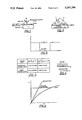
- T 2 is the fully onstate (value 0) as shown in FIG. 6.
- the speed, or modulation frequency will be as great as possible.
- real systems have limited W and speed.
- T 1 is the interaction length, L, is short, T 1 is low in the usual case. If the interaction length, L, is very long, it is usually the case that T 1 is high (which makes the modulator system bulky and inefficient).
- a moderate interaction length can be measured in millimeters, while a short interaction length is less than a millimeter.
- the drive voltage of MQW technology is higher than SPW technology.
- MQW voltage levels are -10 volts and SPW voltage levels are less than one volt.
- Lower drive voltages mean less power consumption.
- Insertion loss for the SPW system is only -3 db per meter, whereas insertion losses for MQW are -3 db per centimeter. Insertion loss is a measurement of off-state absorption. Note that the insertion loss of SPW modulators is measured on the meter scale.
- MQW modulators The cost of making MQW modulators is very high, while the cost of the SPW technology is low.
- the cost of MQW technology is high in part because it requires sophisticated GaAs VLSI processing.
- the laser damage threshold of SPW modulators is extremely high, while that of MQW technology is low. All semiconductor devices, including MQW devices, have poor laser damage thresholds and are highly temperature sensitive. Similarly, ruggedization and environmental stability is low for MQW modulators and high for SPW modulators.
- MQW technology is closely related to laser diode (LD) technology which is likewise semiconductor based, while the SPW technology is dielectric based and thus closely related to low insertion loss fiber-optic media technology. Therefore, in contrast to MQWs, SPWs can also be used in high power laser switching and modulation with very high laser damage thresholds, greater than 1 GW per cm 2 .
- LD laser diode
- SPWs can also be used in high power laser switching and modulation with very high laser damage thresholds, greater than 1 GW per cm 2 .
- Highly sensitive passive sensing devices based on surface plasmon wave interaction have been used to sense a broad variety of conditions.
- the condition to be sensed changes the optical properties of the sensing medium which in turn changes the resonance conditions.
- TM intensity also changes.
- the intensity change can be detected at the other end of the fiber and is a measure of the field to be sensed.
- passive sensors may be used to sense gases, chemicals, temperature, stress, strain and magnetic fields, for example. These types of sensors are discussed in "Fiber-Optic Sensor Based on Surface Plasmon Wave Resonant Coupling", Poster Paper: Meeting of OSA (Opt. Soc. of Amer.) October, 1988, Santa Clara, Calif.
- a prism-based surface plasmon sensor is disclosed in U.S. Pat. No. 4,844,613.
- surface plasmon wave modulators are of the bulk-optic type, wherein a prism is used to effect coupling between a free-space light beam, whose source is usually a bulky and expensive laser such as HeNe, and the metal-dielectric interface which supports the surface plasmon wave.
- Bulk type systems suffer from stability and alignment problems.
- the speed advantage of SPW bulk-optic systems is not much greater than MQW type systems. A super high speed non-bulk SPW modulator is needed.
- a surface plasmon wave modulator is presented. Specifically, a surface plasmon wave modulator employing polymer glass materials and a super fast electro-optic controlling medium for modulating laser light at ultrahigh frequencies is disclosed.
- the active surface plasmon modulator may be configured in either a planar integrated or fiber-optic format by coupling a guided light wave with a surface plasmon wave generated at the interface of a metal electrode and an electro-optic material disposed close to the optical path containing the guided light waves.
- the light wave is totally internally reflected within the path and is surrounded by an evanescent wave which extends outside of the boundaries of the path.
- a surface plasmon wave is generated at the metal-electro-optic material interface by applying an external electromagnetic field to the metal electrodes on either side of the material.
- the surface plasmon wave is coupled with the evanescent wave portion of the light wave traveling in the optical path.
- the coupling between the two waves is strong the light energy is absorbed by the surface plasmon wave and the intensity of the light decreases.
- the coupling between the two waves is weak the intensity of the light wave is less attenuated.
- the advantageous structure of the surface plasmon modulator of the present invention eliminates the bulk and alignment problems of bulk type modulators and allows the switching system comprising the metal-dielectric interface to be located totally externally of the light source and the light wave guide significantly lowering beam deformation and insertion losses.
- the modulator may also be used in integrated optic circuits where size constraints govern. Switching can be achieved with changes in the index of refraction of the electro-optic material of less than 10 -3 thus making the voltage requirements of the surface plasmon modulator minimal.
- FIG. 1 is a schematic of a prior art surface plasmon wave generator by Otto;
- FIG. is a schematic of a prior art surface plasmon wave generator by Kretschmann
- FIG. 3 is a chart comparing the index of refraction changes achievable with different combinations of metals and dielectrics in a modulator of the present invention
- FIG. 5 is a dispersion diagram showing that the momentum and energy conservation laws cannot be satisfied simultaneously by direct coupling
- FIG. 6 is a schematic of the on and off transmission states versus time of a surface plasmon wave modulator
- FIGS. 7A and 7B are schematics of a surface plasmon wave modulator in planar format of the present invention.
- FIGS. 8A-D are various graphs showing the dependency of resonance and losses on sensing medium index (8A) and showing the dependency of output intensity and guided mode angle on applied voltage (8B-D);
- FIG. 9 is a schematic of a surface plasmon wave modulator in fiber-optic format of the present invention.
- FIG. 10 is a schematic of a microstrip electrode embodiment of a surface plasmon wave modulator of the present invention.
- TM polarization A preferred embodiment of the plasmon wave modulator which operates in the electromagnetic mode (TM polarization), presents a strongly localized plasmon wave at its interface (maximum at the interface and exponentially decaying away from the interface), has a complex propagation constant which is extremely sensitive to optical properties very near the interface, and has high light wave propagation losses for TM polarization is now described.
- the surface plasmon wave modulator 10 is an active planar, multilayer structure comprising a single-mode planar optical path (planar waveguide) 12 sandwiched between two layers of cladding material 14 against the lower layer of which are disposed two metal electrodes 18A, 18B and electro-optic material 20 sandwiched between the metal electrodes.
- the respective refractive indices of each of the layers in the multilayer structure 10 can be seen in FIG. 7B.
- the uppermost layer of cladding material 14 has refractive index n 1
- the planar waveguide has refractive index n 2
- the lower layer of cladding material 14 has refractive index n 3
- the buffer, refractive index n 4 both metal electrodes have complex refractive index n 5
- the electro-optic material has refractive index n 6 .
- FIG. 7B Also shown in FIG. 7B is a schematic of the refractive indices of each of the layers which shows the relative refractive indices of each layer. It can be seen that the refractive index n 2 of the waveguide is larger than the refractive indices n 1 and n 3 of the cladding, and the refractive index n 2 is larger than the refractive index n 4 of the buffer. It can also been seen that the refractive index, n 6 , of the electro-optic material is less than the refractive index, n 2 , of the waveguide.
- the relative thicknesses of the layers in the planar multilayer surface plasmon wave modulator structure 10 are critical to obtaining coupling of the TM portion of the light wave and the surface plasmon wave generated at the metal-electro-optic material interface.
- the distance between the waveguide 12 and the metal dielectric interface between electrode 18A and electro-optic material 20 must be short.
- the thickness of the lower cladding layer 14, the buffer 16 (approximately 0.1 um), both electrodes 18A, 18B and the electro-optic material sandwiched between them may preferably be on the order of only 0.5 um, while the thickness of the planar waveguide 12 may preferably be 6 um.
- the surface plasmon wave modulator 10 has a thickness on the order of 10 um including the waveguide layer.
- the overall length of the electrode-electro-optic material sandwich 18A, 18B, and 20 can be short, on the order of 100 um and defines the active region of the modulator 10. Likewise, the length of the electrode can be extremely short, on the order of 10 um.
- the highly integrated architecture of the modulator 10 makes it extremely compact, as well as rugged and resistant to environmental influences.
- the cladding 14 may preferably be cladding typically used for encasing optical waveguides.
- the most important limitation of the cladding is that the layer of cladding between the waveguide and the electro-optic material must be kept thin.
- the optical waveguide 12 may preferably be a waveguide that supports only one light wave mode, i.e., a single mode waveguide. Because the electro-optic material 20 is separated from the waveguide 12 by two intermediate thin layers of cladding 14 and buffer 16, the waveguide 12 material can be neutral such as GaAs (or glass), for example.
- the waveguide material can be any optically transparent material suitable for the transmission of an optical wave.
- the buffer can be made of a dielectric material of refractive index less than the waveguide material.
- a preferred buffer material is calcium floride CaF 2 .
- the metal electrodes 18A, 18B may preferably be made of metals such as gold, aluminum, silver, or other similar metals and may be on the order of 100 A thin.
- a superconductor such as YeBaCuO may also be used.
- the electro-optic material 20 may preferably be a second order nonlinear polymer, called an electro-optic polymer, which has a response time measured in picoseconds and very low refractive index amplitude modulation requirements (less than 10 -2 ).
- Electro-optic polymers include those made by Dupont and Celanese. A preferred polymer is methyl nitro aniline.
- liquid crystals, such as ferroelectric crystals which have one nanosecond response times have been used and may be used in the present invention as well.
- liquid crystals usually have high voltage requirements, on the order of 10 volts.
- Newer polymers such as Celenese polymer require only 3.3 volts.
- the preferred electro-optic polymers of the present invention require voltages on the order of one volt.
- the typical LC speed is one millisecond, and for smectic LCs is about 20 nanoseconds, and for PLZT is less than 70 nanoseconds, while for typical electro-optic polymers, the speed is far higher, less than one picosecond.
- the preferred electro-optic polymers are better than LCs in three important respects: required voltage is smaller by two orders of magnitude, speed is higher by three orders of magnitude, and the contrast ratio is better by one order of magnitude, while transmission is comparable for the two types of materials in the most important near IR region (0.7-1.3 um).
- Photorefractive materials such as PLZT, which require higher driving voltages, may be used as well.
- the extremely high sensitivity and super-fast response times of electro-optic polymers make them the material of choice for the electro-optic material 20 layer of the modulator 10 of the present invention.
- the surface plasmon wave modulator 10 is operated by the interaction of the evanescent wave produced by single-mode waveguide 12 of a light wave emitted by, for example, a laser diode (LD).
- the waveguide 12 may preferably support only one mode due to its extreme thinness.
- a voltage applied across the metal electrodes 18A, 18B changes the refractive index n 6 of the electro-optic material 20. The amount of voltage needed is directly related to the sensitivity of the electro-optic material 20 chosen for the particular surface plasmon wave modulator 10.
- Two different optical modes can be supported in the surface plasmon wave modulator 10: (1) a guided mode of the waveguide 12 core, and (2) a surface plasmon mode in the interface between the metallic foil 18 and the electro-optic layer 20.
- Energy from the guided core mode is resonantly coupled to the surface plasmon wave interface mode if the phase velocities of the two modes are matched.
- the phase matching condition is controlled by the refractive index of the electro-optic material 20 by applying an electric field.
- the thin buffer layer 16 aides in satisfying the phase-matching condition.
- the TM polarization component of the light wave couples into the surface plasmon wave interface mode, while the TE polarization propagates through unchanged.
- the input light is TM polarized then its power will couple into the interface mode for the phase matched case.
- the TM polarization power goes through unchanged if not phased matched, while the interface mode dissipates in the metallic foil as ohmic heat.
- the output power level is controlled by the applied field. Note that the switching system comprising the metal electrodes 18A, 18B and the electro-optic material 20 is located totally externally not only to the LD but also to the waveguide. This significantly lowers beam deformation and insertion losses.
- the curves of FIG. 8A are derived by solving Maxwell's equations for the single mode propagation of the TM polarization of the light wave traveling in waveguide 12. It can be seen that the curve 26, which represents TM loss, changes abruptly at a sensing medium refractive index of n spw . At this point, TM propagation losses rise dramatically from about 2 db/mm to roughly 75 db/mm.
- FIGS. 8B-D show the effect of varying the voltage applied to the electro-optic material-metal electrode sandwich on intensity.
- FIG. 8B generally shows output intensity versus the angle of the guided mode wave in the waveguide for fixed voltage and wavelength.
- FIG. 8C shows output intensity versus guided mode angle for two different voltages and fixed wavelength. Note that the application of voltage shifts the resonance point.
- the output intensity changes vertically between points A and B on vertical line 29 on the V 1 and V 2 curves, respectively.
- the angle of the guided mode in the waveguide is different. The higher voltage V 2 corresponds to a higher guided mode angle.
- FIG. 8D shows the refractive index changes for the two voltages V 1 and V 2 .
- n v2 n v1 + ⁇ n, where n v2 equals the refractive index of the electro-optic material at voltage V 2 , n v1 is the refractive index of the electro-optic material at voltage V 1 , and ⁇ n is the difference between the two indices at those two voltages.
- n v2 n v1 + ⁇ n
- the curves in FIG. 8 are different for different wavelength light waves.
- the laser diode light is introduced to the waveguide in such a way that its propagation wave vector is near the cut-off resonance frequency of modal characteristic of the waveguide.
- the wavelength of the light in waveguide 12 is adjusted close to the resonant wavelength (or vice versa depending on system constraints) and Maxwell's equations with boundary conditions are solved to obtain the FIG. 8 type curves for a particular modulator.
- the particular resonant frequency For a particular electro-optic material having index of refraction n 6 , the particular resonant frequency must be found. Once that value is found the light source is set close to that resonance so that only very small changes in the refractive index of electro-optic material 20 are needed to cause the material to resonate and its surface plasmon waves to couple with the light wave mode. As a result, the intensity loss of the TM waveguide mode can achieve a very high slope of 1 dB per 3 ⁇ 10 -3 change in the refractive index of the externally positioned electro-optic material 20.
- the modulator 10's sensitivity to changes in the external refractive index modulation may be increased to 10 -4 by making the length of interaction between the light and perturbed waveguide sufficiently long, i.e. larger than 10 um.
- the interaction length is extremely short, due to the small area of electrodes 18A, 18B, which in turn results in a very short time constant for the system.
- the response of the modulator 10, therefore, is only slightly limited by the structure of the modulator 10 and is determined mainly by the choice of electro-optic material 20 which may include second-order non-linear polymers.
- the electrodes can be made of superconductive material, such as SrCaCuO or YBCuO, with extremely low ohmic loss.
- the operation of the surface plasmon wave modulator 10 is based on the effect of coupling between the surface plasmon wave mode and the evanescent wave portion of the light wave mode traveling in the waveguide 12. Because the electrode-electro-optic material sandwich is located completely external of the waveguide, the surface plasmon mode affects virtually only the evanescent wave of the light wave in the waveguide 12.
- evanescent waves An inevitable result of total internal reflection of a light wave traveling in an optical path is the occurrence of electromagnetic energy in the form of evanescent waves propagating in the cladding material in the same direction as the guided waves in the fiber core.
- Evanescent waves do not carry energy radially out of the fiber, but they do carry power along the fiber, as a kind of overflow of the light confined within.
- evanescent waves are standing waves with exponentially decreasing amplitude, with the 1/e distance typically kept to a fraction of the cladding radius, on the order of 0.5 um. If the energy of the evanescent waves is removed or absorbed in any way, more comes out of the fiber core to take its place.
- the intensity of the light traveling in the waveguide 12 may be reduced or possibly extinguished.
- this power leakage is not desired, because it is detrimental to the fiber's purpose of effective light transmission over long distances.
- the amplitude of the light in the waveguide or fiber can be modulated thereby encoding it with information or creating a pulsed light source from a nonpulsed one.
- Modulation of light amplitude can be done at extremely high frequencies such as microwave frequency, and thus the modulator 10 can achieve frequency modulation in the terahertz range. This can be accomplished with refractive index changes of the electro-optic material of only 10 -4 or less by making the interaction length, L, slightly greater.
- FIG. 9 a surface plasmon wave modulator 30 in a fiber-optic implementation is depicted.
- a fiber-optic cable 32 having cladding 34 and core 36 is shown with a portion of its cladding removed.
- a buffer layer 38 is disposed on the area of the cable having the reduced cladding diameter.
- a metal film 40 is disposed on top of the buffer layer and an electro-optic material 42 and another metal electrode 44 are disposed on top of metal film 40.
- Light waves traveling in core 36 having evanescent wave portions extending outside of core 36 and into the cladding 32 and buffer layer 38 can be coupled with surface plasmon waves generated at the interface of the metal 40 and electro-optic material 42 by applying a voltage across the metal electrodes 40, 44 sufficient to cause a change in the refractive index of the electro-optic material 42 and cause it to resonate.
- the TM portion of the light wave propagating in the core 36 can be absorbed by the surface plasmon wave at the resonant frequency of the electro-optic material.
- the light in the core 36 can thereby be pulsed at extremely high frequencies to create, say for example, a pulse laser or can be encoded with information to be transferred down the fiber-optic cable over great distances.
- the modulators 10 and 30 are extremely sensitive to changes in the refractive index of the electro-optic material caused by the application of the high frequency voltage to the metal electrodes, and at a particular refractive index value of the electro-optic material, the TM mode of the light wave couples into the lossy surface plasmon mode by resonant coupling.
- a traveling wave electrode structure is needed.
- a high frequency (substantially greater than 1 GHz) traveling wave with a 50 ohm impedance matched electrode structure 50 is shown.
- coaxial cable 52 containing microwave energy is coupled to a microstrip electrode 54 which is disposed on top of electro-optic material 56 underneath which is a second microstrip electrode 58.
- the optical wave to be modulated travels in the planar waveguide 60 which is the uppermost layer of the structure 50.
- the microwave energy in the coaxial cable 52 changes the refractive index of the electro-optic material 56 and at the resonant frequency of the electro-optic material 56 the surface plasmon wave traveling at the interface of the electro-optic material 56 and the microstrip electrode 54 couples with the evanescent wave portion of the light wave traveling in planar waveguide 60.
- the intensity of the light wave is thus decreased in accordance with variations in the frequency and energy of the microwave energy traveling in coaxial cable 52.
- the essential condition is the matching of phase velocities of both electromagnetic waves, microwave and optical, which can be done by proper adjustment of the relative material constants of the various layers.
- a conventional laser diode with a grin lens may be employed to edge couple the light wave, which may be in the form of laser light, into the waveguide 60.
- the output light may be detected by a photodetector for analysis.
- the frequency response of the plasmon modulator may be measured by using a microwave measurement system including a sweep oscillator to drive the electrodes, a high-speed GaAs photodetector, and a spectrum analyzer receiving the photodetector current.
- a desktop computer may be used to control the oscillator and spectrum analyzer and graphically represent the measurements.
Abstract
Description
E=hv. (Eq. 1)
ε.sub.m =ε.sub.real +iε.sub.imag (Eq. 2), ##EQU1## where m is the electron mass and n=10.sup.23. Thus the following obtains:
f.sub.p bulk=3×10.sup.15 Hz or λ.sub.p bulk=0.1 um(Eq. 5)
n.sub.SPW =n.sup.R.sub.SPW +in.sup.I.sub.SPW (Eq. 7)
(db)=10 log.sub.e -2k n.sup.I SPW×L (Eq. 9)
or loss ##EQU4## where λ.sub.0 is the light wavelength in vacuum.
ER=off-state intensity/on-state intensity. (Eq. 11)
ER=W=T.sub.1 /T.sub.2 (Eq. 12)
Claims (12)
Priority Applications (2)
| Application Number | Priority Date | Filing Date | Title |
|---|---|---|---|
| US07/496,799 US5067788A (en) | 1990-03-21 | 1990-03-21 | High modulation rate optical plasmon waveguide modulator |
| JP3078254A JPH05313108A (en) | 1990-03-21 | 1991-03-19 | Optical modulator |
Applications Claiming Priority (1)
| Application Number | Priority Date | Filing Date | Title |
|---|---|---|---|
| US07/496,799 US5067788A (en) | 1990-03-21 | 1990-03-21 | High modulation rate optical plasmon waveguide modulator |
Publications (1)
| Publication Number | Publication Date |
|---|---|
| US5067788A true US5067788A (en) | 1991-11-26 |
Family
ID=23974187
Family Applications (1)
| Application Number | Title | Priority Date | Filing Date |
|---|---|---|---|
| US07/496,799 Expired - Lifetime US5067788A (en) | 1990-03-21 | 1990-03-21 | High modulation rate optical plasmon waveguide modulator |
Country Status (2)
| Country | Link |
|---|---|
| US (1) | US5067788A (en) |
| JP (1) | JPH05313108A (en) |
Cited By (91)
| Publication number | Priority date | Publication date | Assignee | Title |
|---|---|---|---|---|
| US5131060A (en) * | 1990-07-09 | 1992-07-14 | Canon Kabushiki Kaisha | Optical waveguide modulator communications device and method of modulating light using same |
| WO1993016409A1 (en) * | 1992-02-11 | 1993-08-19 | Valtion Teknillinen Tutkimuskeskus | Method for transferring visual information |
| US5359681A (en) * | 1993-01-11 | 1994-10-25 | University Of Washington | Fiber optic sensor and methods and apparatus relating thereto |
| US5606633A (en) * | 1995-06-26 | 1997-02-25 | American Research Corporation Of Virginia | Chemical detector employing surface plasmon resonance excited using an optical waveguide configured as an asymmetric waveguide coupler |
| US5729641A (en) * | 1996-05-30 | 1998-03-17 | Sdl, Inc. | Optical device employing edge-coupled waveguide geometry |
| US5854864A (en) * | 1996-07-16 | 1998-12-29 | The Regents Of The University Of California | In-line polymeric construct for modulators, filters, switches and other electro-optic devices |
| US5858799A (en) * | 1995-10-25 | 1999-01-12 | University Of Washington | Surface plasmon resonance chemical electrode |
| US5892857A (en) * | 1997-01-21 | 1999-04-06 | Molecular Optoelectronics Corporation | Electro-optic compound waveguide intensity modular and method using same |
| WO1999049353A1 (en) * | 1998-03-26 | 1999-09-30 | Verifiber Technologies, Inc. | Optical plasmon-wave structures |
| US5982961A (en) * | 1997-01-21 | 1999-11-09 | Molecular Optoelectronics Corporation | Organic crystal compound optical waveguide and methods for its fabrication |
| WO1999060731A1 (en) * | 1998-05-19 | 1999-11-25 | Verifiber Technologies, Inc. | Optical surface plasmon-wave communications systems |
| US5995270A (en) * | 1996-10-17 | 1999-11-30 | Nippon Telegraph & Telephone Corporation | Ultra-high-speed semiconductor optical modulator with traveling-wave electrode |
| US6021240A (en) * | 1997-10-02 | 2000-02-01 | F&S, Inc. | Optical sensor activation device |
| US6026205A (en) * | 1997-01-21 | 2000-02-15 | Molecular Optoelectronics Corporation | Compound optical waveguide and filter applications thereof |
| US6091879A (en) * | 1998-09-15 | 2000-07-18 | Molecular Optoelectronics Corporation | Organic photochromic compositions and method for fabrication of polymer waveguides |
| EP1057054A1 (en) * | 1998-02-20 | 2000-12-06 | Molecular Optoelectronics Corporation | Fiber optic attenuators and attenuation systems |
| US6169594B1 (en) | 1998-08-24 | 2001-01-02 | Physical Optics Corporation | Beam deflector and scanner |
| US6178275B1 (en) * | 1997-05-01 | 2001-01-23 | The Trustees Of The Stevens Institute Of Technology | Method and apparatus for modulation of guided plasmons |
| US6275628B1 (en) | 1998-12-10 | 2001-08-14 | Luna Innovations, Inc. | Single-ended long period grating optical device |
| US6300638B1 (en) | 1998-11-12 | 2001-10-09 | Calspan Srl Corporation | Modular probe for total internal reflection fluorescence spectroscopy |
| US6303695B1 (en) | 1998-08-25 | 2001-10-16 | Molecular Optoelectronics Corporation | Dispersion-controlled polymers for broadband fiber optic devices |
| US6343168B1 (en) | 1997-10-02 | 2002-01-29 | Luna Innovations, Inc. | Optical sensor arrangement |
| US6366723B1 (en) | 1998-09-16 | 2002-04-02 | Jolt Ltd. | Wireless optical communications without electronics |
| US6437887B1 (en) * | 1999-03-02 | 2002-08-20 | Fuji Photo Film Co., Ltd. | Optical logic device and optical memory device |
| US6442321B1 (en) | 1999-12-23 | 2002-08-27 | Spectalis Corp. | Optical waveguide structures |
| US6466729B1 (en) | 2000-03-30 | 2002-10-15 | Molecular Optoelectronics Corporation | Controllable fiber optic attenuators employing tapered and/or etched fiber sections |
| US20020168170A1 (en) * | 1998-08-25 | 2002-11-14 | Molecular Optoelectronics Corporation | Blockless fiber optic attenuators and attenuation systems employing dispersion tailored polymers |
| US6483981B1 (en) | 2000-06-28 | 2002-11-19 | Molecular Optoelectronics Corp. | Single-channel attenuators |
| US6489399B1 (en) | 2000-07-31 | 2002-12-03 | Molecular Optoelectronics Corp. | Dye-appended polymers for broadband fiber optic devices |
| US20020192836A1 (en) * | 1997-06-10 | 2002-12-19 | Calspan Srl Corporation | Detection of chemical agent materials using a sorbent polymer and fluorescent probe |
| US20030020625A1 (en) * | 1997-10-21 | 2003-01-30 | Pederson John C. | Led warning signal light and light support |
| US20030133339A1 (en) * | 2001-05-21 | 2003-07-17 | Estes Michael J. | Interconnected high speed electron tunneling devices |
| US6611649B2 (en) | 2001-03-19 | 2003-08-26 | Molecular Optoelectronics Corporation | Variable optical attenuator with polarization maintaining fiber |
| US6614960B2 (en) | 1999-12-23 | 2003-09-02 | Speotalis Corp. | Optical waveguide structures |
| US6623151B2 (en) | 1999-08-04 | 2003-09-23 | 911Ep, Inc. | LED double light bar and warning light signal |
| US20030179974A1 (en) * | 2002-03-20 | 2003-09-25 | Estes Michael J. | Surface plasmon devices |
| US20030206708A1 (en) * | 2002-03-20 | 2003-11-06 | Estes Michael J. | Surface plasmon devices |
| US20030223668A1 (en) * | 2002-05-31 | 2003-12-04 | Breukelaar Ian Gregory | Electro-optic modulators |
| US6681073B2 (en) | 2001-03-19 | 2004-01-20 | Molecular Optoelectronics Corporation | Fiber optic power control systems and methods |
| US6693551B2 (en) | 1999-04-06 | 2004-02-17 | 911Ep, Inc. | Replaceable led modules |
| US6707389B2 (en) | 1999-08-04 | 2004-03-16 | 911Ep, Inc. | LED personal warning light |
| US6744909B1 (en) | 1999-08-19 | 2004-06-01 | Physical Optics Corporation | Authentication system and method |
| US20040120649A1 (en) * | 2002-12-20 | 2004-06-24 | Motorola, Inc. | Optical coupling interface for optical waveguide and optical fiber |
| US6782179B2 (en) * | 2000-07-21 | 2004-08-24 | Micro Managed Photons A/S | Surface plasmon polariton band gap structures |
| US20040197968A1 (en) * | 2003-04-02 | 2004-10-07 | Chia-Tien Peng | [low temperature polysilicon thin film transistor and method of forming polysilicon layer of same] |
| US20040218185A1 (en) * | 2003-05-01 | 2004-11-04 | Canon Kabushiki Kaisha | Position sensor, method for detecting horizontal and vertical position, alignment apparatus including position sensor, and method for horizontal and vertical alignment |
| US20040232505A1 (en) * | 2001-05-21 | 2004-11-25 | Garret Moddel | High speed electron tunneling devices |
| US20050001562A1 (en) * | 2003-07-02 | 2005-01-06 | 911Ep, Inc. | LED compensation circuit |
| US6845118B1 (en) * | 1999-01-25 | 2005-01-18 | Optical Communication Products, Inc. | Encapsulated optoelectronic devices with controlled properties |
| US6879263B2 (en) | 2000-11-15 | 2005-04-12 | Federal Law Enforcement, Inc. | LED warning light and communication system |
| US20050135249A1 (en) * | 2003-12-19 | 2005-06-23 | International Business Machines Corporation | Autonomic reassociation of clients in a wireless local area network |
| US20050248830A1 (en) * | 2004-05-10 | 2005-11-10 | Ray Sawin | Electro-optic array interface |
| US20060012000A1 (en) * | 2001-05-21 | 2006-01-19 | Estes Michael J | Thin-film transistors based on tunneling structures and applications |
| US6989743B2 (en) | 1999-04-06 | 2006-01-24 | 911Ep, Inc. | Replacement LED lamp assembly and modulated power intensity for light source |
| US6995681B2 (en) | 1997-10-21 | 2006-02-07 | 911Ep, Inc. | LED warning signal light and movable support |
| US20060038168A1 (en) * | 2001-05-21 | 2006-02-23 | Estes Michael J | Terahertz interconnect system and applications |
| US7038593B2 (en) | 1999-06-08 | 2006-05-02 | 911Ep, Inc. | Strip LED light assembly for motor vehicle |
| US7043134B2 (en) | 1999-12-23 | 2006-05-09 | Spectalis Corp. | Thermo-optic plasmon-polariton devices |
| US7080930B2 (en) | 1999-06-08 | 2006-07-25 | 911Ep, Inc. | LED warning signal light and row of LED's |
| US7163324B2 (en) | 1999-06-08 | 2007-01-16 | 911Ep, Inc. | Led light stick assembly |
| US7196950B2 (en) | 2002-10-30 | 2007-03-27 | Kabushiki Kaisha Toshiba | Non-volatile semiconductor storage device performing ROM read operation upon power-on |
| US20070258673A1 (en) * | 2006-05-08 | 2007-11-08 | El-Sherif Mahmoud A | On-fiber tunable bragg gratings for DWDM applications |
| US20080084597A1 (en) * | 2006-10-06 | 2008-04-10 | Matsushita Electric Industrial Co., Ltd. | Optical modulator and optical modulation method |
| US20080180340A1 (en) * | 2007-01-31 | 2008-07-31 | International Business Machines Corporation | Waveguide Coupling Devices |
| US7439847B2 (en) | 2002-08-23 | 2008-10-21 | John C. Pederson | Intelligent observation and identification database system |
| US20080292320A1 (en) * | 2007-05-24 | 2008-11-27 | Federal Law Enforcement Development Service, Inc. | Led light global positioning and routing communication system |
| US20080310850A1 (en) * | 2000-11-15 | 2008-12-18 | Federal Law Enforcement Development Services, Inc. | Led light communication system |
| US20090028493A1 (en) * | 2007-07-26 | 2009-01-29 | Fattal David A | Plasmon-enhanced electromagnetic-radiation-emitting devices and methods for fabricating the same |
| US20090052827A1 (en) * | 2006-10-09 | 2009-02-26 | Colorado School Of Mines | Silicon-Compatible Surface Plasmon Optical Elements |
| WO2009002524A3 (en) * | 2007-06-26 | 2009-02-26 | Hewlett Packard Development Co | Electric-field-enhancement structure and detection apparatus using same |
| US20100039693A1 (en) * | 2008-08-15 | 2010-02-18 | Andrey Kobyakov | Surface-Plasmon-Based Optical Modulator |
| US7705415B1 (en) | 2004-08-12 | 2010-04-27 | Drexel University | Optical and electronic devices based on nano-plasma |
| US20100103495A1 (en) * | 2008-10-28 | 2010-04-29 | Boise State University | Surface plasmon optical modulator |
| JP2010145399A (en) * | 2008-12-16 | 2010-07-01 | Rohm Co Ltd | Mixed coupling structure of short-range surface plasmon polariton and general dielectric waveguide, coupling structure of long-range surface plasmon polariton and dielectric waveguide, and its application |
| US20100202728A1 (en) * | 2009-02-10 | 2010-08-12 | Alcatel-Lucent Usa Inc. | Surface-plasmon-assisted optical frequency conversion |
| US20100316327A1 (en) * | 2009-02-13 | 2010-12-16 | Juan Montoya | Surface Plasmon Enhanced Optical Devices for Integrated Photonics |
| US20130120752A1 (en) * | 2011-11-11 | 2013-05-16 | Kyeong Seok Lee | Fiber-optic surface plasmon resonance sensor and sensing method using the same |
| US8543505B2 (en) | 2011-01-14 | 2013-09-24 | Federal Law Enforcement Development Services, Inc. | Method of providing lumens and tracking of lumen consumption |
| US8890773B1 (en) | 2009-04-01 | 2014-11-18 | Federal Law Enforcement Development Services, Inc. | Visible light transceiver glasses |
| US8909002B2 (en) | 2012-04-05 | 2014-12-09 | Panasonic Corporation | Light modulator, optical pickup, and light modulation module |
| US9024297B2 (en) | 2010-09-17 | 2015-05-05 | The Governors Of The University Of Alberta | Two- and three-terminal molecular electronic devices with ballistic electron transport |
| US9100124B2 (en) | 2007-05-24 | 2015-08-04 | Federal Law Enforcement Development Services, Inc. | LED Light Fixture |
| US9258864B2 (en) | 2007-05-24 | 2016-02-09 | Federal Law Enforcement Development Services, Inc. | LED light control and management system |
| US9265112B2 (en) | 2013-03-13 | 2016-02-16 | Federal Law Enforcement Development Services, Inc. | LED light control and management system |
| US9294198B2 (en) | 2007-05-24 | 2016-03-22 | Federal Law Enforcement Development Services, Inc. | Pulsed light communication key |
| US9414458B2 (en) | 2007-05-24 | 2016-08-09 | Federal Law Enforcement Development Services, Inc. | LED light control assembly and system |
| US9455783B2 (en) | 2013-05-06 | 2016-09-27 | Federal Law Enforcement Development Services, Inc. | Network security and variable pulse wave form with continuous communication |
| US20170329127A1 (en) * | 2016-05-12 | 2017-11-16 | The Chinese University Of Hong Kong | Light modulator using total internal reflection at an interface with a tunable conductive layer |
| US10448472B2 (en) | 2015-08-11 | 2019-10-15 | Federal Law Enforcement Development Services, Inc. | Function disabler device and system |
| US11265082B2 (en) | 2007-05-24 | 2022-03-01 | Federal Law Enforcement Development Services, Inc. | LED light control assembly and system |
| US11783345B2 (en) | 2014-01-15 | 2023-10-10 | Federal Law Enforcement Development Services, Inc. | Cyber life electronic networking and commerce operating exchange |
Families Citing this family (3)
| Publication number | Priority date | Publication date | Assignee | Title |
|---|---|---|---|---|
| JP3402253B2 (en) | 1999-05-14 | 2003-05-06 | 日本電気株式会社 | Light modulation element, light source and display device using the same, and method of driving the same |
| KR101647046B1 (en) | 2010-09-03 | 2016-08-10 | 삼성전자주식회사 | Surface plasmon polariton modulator |
| SG11201707714SA (en) * | 2015-04-01 | 2017-10-30 | ETH Zürich | Electrooptic modulator |
Citations (4)
| Publication number | Priority date | Publication date | Assignee | Title |
|---|---|---|---|---|
| US4765705A (en) * | 1983-03-11 | 1988-08-23 | Gte Laboratories Incorporated | Grating surface plasmon coupler |
| US4844613A (en) * | 1986-11-03 | 1989-07-04 | Stc Plc | Optical surface plasmon sensor device |
| US4877747A (en) * | 1985-04-12 | 1989-10-31 | Plessey Overseas Limited | Optical assay: method and apparatus |
| US4915482A (en) * | 1988-10-27 | 1990-04-10 | International Business Machines Corporation | Optical modulator |
-
1990
- 1990-03-21 US US07/496,799 patent/US5067788A/en not_active Expired - Lifetime
-
1991
- 1991-03-19 JP JP3078254A patent/JPH05313108A/en active Pending
Patent Citations (4)
| Publication number | Priority date | Publication date | Assignee | Title |
|---|---|---|---|---|
| US4765705A (en) * | 1983-03-11 | 1988-08-23 | Gte Laboratories Incorporated | Grating surface plasmon coupler |
| US4877747A (en) * | 1985-04-12 | 1989-10-31 | Plessey Overseas Limited | Optical assay: method and apparatus |
| US4844613A (en) * | 1986-11-03 | 1989-07-04 | Stc Plc | Optical surface plasmon sensor device |
| US4915482A (en) * | 1988-10-27 | 1990-04-10 | International Business Machines Corporation | Optical modulator |
Cited By (195)
| Publication number | Priority date | Publication date | Assignee | Title |
|---|---|---|---|---|
| US5131060A (en) * | 1990-07-09 | 1992-07-14 | Canon Kabushiki Kaisha | Optical waveguide modulator communications device and method of modulating light using same |
| WO1993016409A1 (en) * | 1992-02-11 | 1993-08-19 | Valtion Teknillinen Tutkimuskeskus | Method for transferring visual information |
| US5835645A (en) * | 1993-01-11 | 1998-11-10 | University Of Washington | Fiber optic sensor and methods and apparatus relating thereto |
| US5359681A (en) * | 1993-01-11 | 1994-10-25 | University Of Washington | Fiber optic sensor and methods and apparatus relating thereto |
| US5647030A (en) * | 1993-01-11 | 1997-07-08 | University Of Washington | Fiber optic sensor and methods and apparatus relating thereto |
| US5606633A (en) * | 1995-06-26 | 1997-02-25 | American Research Corporation Of Virginia | Chemical detector employing surface plasmon resonance excited using an optical waveguide configured as an asymmetric waveguide coupler |
| US5858799A (en) * | 1995-10-25 | 1999-01-12 | University Of Washington | Surface plasmon resonance chemical electrode |
| US5729641A (en) * | 1996-05-30 | 1998-03-17 | Sdl, Inc. | Optical device employing edge-coupled waveguide geometry |
| US5854864A (en) * | 1996-07-16 | 1998-12-29 | The Regents Of The University Of California | In-line polymeric construct for modulators, filters, switches and other electro-optic devices |
| US6047095A (en) * | 1996-07-16 | 2000-04-04 | The Regents Of The University Of California | In-line polymeric construct for modulators, filters, switches and other electro-optic devices |
| US5995270A (en) * | 1996-10-17 | 1999-11-30 | Nippon Telegraph & Telephone Corporation | Ultra-high-speed semiconductor optical modulator with traveling-wave electrode |
| US5892857A (en) * | 1997-01-21 | 1999-04-06 | Molecular Optoelectronics Corporation | Electro-optic compound waveguide intensity modular and method using same |
| US6026205A (en) * | 1997-01-21 | 2000-02-15 | Molecular Optoelectronics Corporation | Compound optical waveguide and filter applications thereof |
| US5982961A (en) * | 1997-01-21 | 1999-11-09 | Molecular Optoelectronics Corporation | Organic crystal compound optical waveguide and methods for its fabrication |
| US6178275B1 (en) * | 1997-05-01 | 2001-01-23 | The Trustees Of The Stevens Institute Of Technology | Method and apparatus for modulation of guided plasmons |
| US20020192836A1 (en) * | 1997-06-10 | 2002-12-19 | Calspan Srl Corporation | Detection of chemical agent materials using a sorbent polymer and fluorescent probe |
| US6021240A (en) * | 1997-10-02 | 2000-02-01 | F&S, Inc. | Optical sensor activation device |
| US6343168B1 (en) | 1997-10-02 | 2002-01-29 | Luna Innovations, Inc. | Optical sensor arrangement |
| US20030020625A1 (en) * | 1997-10-21 | 2003-01-30 | Pederson John C. | Led warning signal light and light support |
| US6788217B2 (en) | 1997-10-21 | 2004-09-07 | 911Ep, Inc. | LED warning signal light and light support having at least one sector |
| US7394398B2 (en) | 1997-10-21 | 2008-07-01 | 911Ep, Inc. | LED warning signal light and light support having at least one sector |
| US6995681B2 (en) | 1997-10-21 | 2006-02-07 | 911Ep, Inc. | LED warning signal light and movable support |
| US7561036B2 (en) | 1997-10-21 | 2009-07-14 | 911 Emergency Products, Inc. | LED warning signal light and light bar |
| EP1057054A4 (en) * | 1998-02-20 | 2001-10-17 | Molecular Optoelectronics Corp | Fiber optic attenuators and attenuation systems |
| EP1057054A1 (en) * | 1998-02-20 | 2000-12-06 | Molecular Optoelectronics Corporation | Fiber optic attenuators and attenuation systems |
| US6370312B1 (en) | 1998-02-20 | 2002-04-09 | Molecular Optoelectronics Corporation | Fiber optic attenuation systems, methods of fabrication thereof and methods of attenuation using the same |
| WO1999049353A1 (en) * | 1998-03-26 | 1999-09-30 | Verifiber Technologies, Inc. | Optical plasmon-wave structures |
| US6034809A (en) * | 1998-03-26 | 2000-03-07 | Verifier Technologies, Inc. | Optical plasmon-wave structures |
| US6282005B1 (en) * | 1998-05-19 | 2001-08-28 | Leo J. Thompson | Optical surface plasmon-wave communications systems |
| WO1999060731A1 (en) * | 1998-05-19 | 1999-11-25 | Verifiber Technologies, Inc. | Optical surface plasmon-wave communications systems |
| US6169594B1 (en) | 1998-08-24 | 2001-01-02 | Physical Optics Corporation | Beam deflector and scanner |
| US6444756B2 (en) | 1998-08-25 | 2002-09-03 | Molecular Optoelectronics Corporation | Dispersion-controlled polymers for broad band fiber optic devices |
| US20020168170A1 (en) * | 1998-08-25 | 2002-11-14 | Molecular Optoelectronics Corporation | Blockless fiber optic attenuators and attenuation systems employing dispersion tailored polymers |
| US6303695B1 (en) | 1998-08-25 | 2001-10-16 | Molecular Optoelectronics Corporation | Dispersion-controlled polymers for broadband fiber optic devices |
| US6785461B2 (en) | 1998-08-25 | 2004-08-31 | Molecular Optoelectronics Corp. | Blockless fiber optic attenuators and attenuation systems employing dispersion tailored polymers |
| US6194120B1 (en) | 1998-09-15 | 2001-02-27 | Molecular Optoelectronics Corporation | Organic photochromic compositions and method for fabrication of polymer waveguides |
| US6091879A (en) * | 1998-09-15 | 2000-07-18 | Molecular Optoelectronics Corporation | Organic photochromic compositions and method for fabrication of polymer waveguides |
| US6366723B1 (en) | 1998-09-16 | 2002-04-02 | Jolt Ltd. | Wireless optical communications without electronics |
| US6300638B1 (en) | 1998-11-12 | 2001-10-09 | Calspan Srl Corporation | Modular probe for total internal reflection fluorescence spectroscopy |
| US6275628B1 (en) | 1998-12-10 | 2001-08-14 | Luna Innovations, Inc. | Single-ended long period grating optical device |
| US6845118B1 (en) * | 1999-01-25 | 2005-01-18 | Optical Communication Products, Inc. | Encapsulated optoelectronic devices with controlled properties |
| US6437887B1 (en) * | 1999-03-02 | 2002-08-20 | Fuji Photo Film Co., Ltd. | Optical logic device and optical memory device |
| US7064674B2 (en) | 1999-04-06 | 2006-06-20 | 911Ep, Inc. | Replaceable LED modules |
| US7498933B2 (en) | 1999-04-06 | 2009-03-03 | 911Ep, Inc. | Replaceable LED modules |
| US6693551B2 (en) | 1999-04-06 | 2004-02-17 | 911Ep, Inc. | Replaceable led modules |
| US6989743B2 (en) | 1999-04-06 | 2006-01-24 | 911Ep, Inc. | Replacement LED lamp assembly and modulated power intensity for light source |
| US7153013B2 (en) | 1999-06-08 | 2006-12-26 | 911Ep, Inc. | LED warning signal light and moveable row of LED's |
| US7163324B2 (en) | 1999-06-08 | 2007-01-16 | 911Ep, Inc. | Led light stick assembly |
| US7095334B2 (en) | 1999-06-08 | 2006-08-22 | 911Ep, Inc. | Strip LED light assembly for motor vehicle |
| US7080930B2 (en) | 1999-06-08 | 2006-07-25 | 911Ep, Inc. | LED warning signal light and row of LED's |
| US7038593B2 (en) | 1999-06-08 | 2006-05-02 | 911Ep, Inc. | Strip LED light assembly for motor vehicle |
| US6814459B2 (en) | 1999-08-04 | 2004-11-09 | 911Ep, Inc. | LED light bar |
| US7033036B2 (en) | 1999-08-04 | 2006-04-25 | 911Ep, Inc. | LED light bar |
| US6707389B2 (en) | 1999-08-04 | 2004-03-16 | 911Ep, Inc. | LED personal warning light |
| US6623151B2 (en) | 1999-08-04 | 2003-09-23 | 911Ep, Inc. | LED double light bar and warning light signal |
| US6744909B1 (en) | 1999-08-19 | 2004-06-01 | Physical Optics Corporation | Authentication system and method |
| US7317814B2 (en) | 1999-08-19 | 2008-01-08 | Physical Optics Corporation | Authentication system and method |
| US7043134B2 (en) | 1999-12-23 | 2006-05-09 | Spectalis Corp. | Thermo-optic plasmon-polariton devices |
| US6614960B2 (en) | 1999-12-23 | 2003-09-02 | Speotalis Corp. | Optical waveguide structures |
| US6442321B1 (en) | 1999-12-23 | 2002-08-27 | Spectalis Corp. | Optical waveguide structures |
| US6466729B1 (en) | 2000-03-30 | 2002-10-15 | Molecular Optoelectronics Corporation | Controllable fiber optic attenuators employing tapered and/or etched fiber sections |
| US6483981B1 (en) | 2000-06-28 | 2002-11-19 | Molecular Optoelectronics Corp. | Single-channel attenuators |
| US6782179B2 (en) * | 2000-07-21 | 2004-08-24 | Micro Managed Photons A/S | Surface plasmon polariton band gap structures |
| US6489399B1 (en) | 2000-07-31 | 2002-12-03 | Molecular Optoelectronics Corp. | Dye-appended polymers for broadband fiber optic devices |
| US20080310850A1 (en) * | 2000-11-15 | 2008-12-18 | Federal Law Enforcement Development Services, Inc. | Led light communication system |
| US20050231381A1 (en) * | 2000-11-15 | 2005-10-20 | Pederson John C | Led warning light and communication system |
| US9413457B2 (en) | 2000-11-15 | 2016-08-09 | Federal Law Enforcement Development Services, Inc. | LED light communication system |
| US7046160B2 (en) | 2000-11-15 | 2006-05-16 | Pederson John C | LED warning light and communication system |
| US6879263B2 (en) | 2000-11-15 | 2005-04-12 | Federal Law Enforcement, Inc. | LED warning light and communication system |
| US8902076B2 (en) | 2000-11-15 | 2014-12-02 | Federal Law Enforcement Development Services, Inc. | LED light communication system |
| US8188878B2 (en) | 2000-11-15 | 2012-05-29 | Federal Law Enforcement Development Services, Inc. | LED light communication system |
| US6681073B2 (en) | 2001-03-19 | 2004-01-20 | Molecular Optoelectronics Corporation | Fiber optic power control systems and methods |
| US6611649B2 (en) | 2001-03-19 | 2003-08-26 | Molecular Optoelectronics Corporation | Variable optical attenuator with polarization maintaining fiber |
| US20040232505A1 (en) * | 2001-05-21 | 2004-11-25 | Garret Moddel | High speed electron tunneling devices |
| US20060038168A1 (en) * | 2001-05-21 | 2006-02-23 | Estes Michael J | Terahertz interconnect system and applications |
| US7595500B2 (en) | 2001-05-21 | 2009-09-29 | University Technology Center Corp | High speed electron tunneling devices |
| US20060012000A1 (en) * | 2001-05-21 | 2006-01-19 | Estes Michael J | Thin-film transistors based on tunneling structures and applications |
| US20030133339A1 (en) * | 2001-05-21 | 2003-07-17 | Estes Michael J. | Interconnected high speed electron tunneling devices |
| US20070120110A1 (en) * | 2001-05-21 | 2007-05-31 | Estes Michael J | Thin-Film Transistors Based on Tunneling Structures and Applications |
| US7105852B2 (en) | 2001-05-21 | 2006-09-12 | University Technology Corporation | High speed electron tunneling devices |
| US7126151B2 (en) | 2001-05-21 | 2006-10-24 | The Regents Of The University Of Colorado, A Body Corporate | Interconnected high speed electron tunneling devices |
| US20070029544A1 (en) * | 2001-05-21 | 2007-02-08 | Estes Michael J | Interconnected high speed electron tunneling devices |
| US20060273301A1 (en) * | 2001-05-21 | 2006-12-07 | Garret Moddel | High speed electron tunneling devices |
| US7173275B2 (en) | 2001-05-21 | 2007-02-06 | Regents Of The University Of Colorado | Thin-film transistors based on tunneling structures and applications |
| US7010183B2 (en) * | 2002-03-20 | 2006-03-07 | The Regents Of The University Of Colorado | Surface plasmon devices |
| US20030179974A1 (en) * | 2002-03-20 | 2003-09-25 | Estes Michael J. | Surface plasmon devices |
| US20030206708A1 (en) * | 2002-03-20 | 2003-11-06 | Estes Michael J. | Surface plasmon devices |
| US7177515B2 (en) | 2002-03-20 | 2007-02-13 | The Regents Of The University Of Colorado | Surface plasmon devices |
| US7418179B2 (en) | 2002-03-20 | 2008-08-26 | The Regents Of The University Of Colorado, A Body Corporate | Surface plasmon devices |
| US20030223668A1 (en) * | 2002-05-31 | 2003-12-04 | Breukelaar Ian Gregory | Electro-optic modulators |
| US6914999B2 (en) | 2002-05-31 | 2005-07-05 | Spectalis Corp. | Electro-optic modulators |
| US7439847B2 (en) | 2002-08-23 | 2008-10-21 | John C. Pederson | Intelligent observation and identification database system |
| US20110157369A1 (en) * | 2002-08-23 | 2011-06-30 | Pederson John C | Intelligent Observation And Identification Database System |
| US8188861B2 (en) | 2002-08-23 | 2012-05-29 | John C. Pederson | Intelligent observation and identification database system |
| US7902978B2 (en) | 2002-08-23 | 2011-03-08 | John C. Pederson | Intelligent observation and identification database system |
| US8330599B2 (en) | 2002-08-23 | 2012-12-11 | John C. Pederson | Intelligent observation and identification database system |
| US8890655B2 (en) | 2002-08-23 | 2014-11-18 | Federal Law Enforcement Development Services, Inc. | Intelligent observation and identification database system |
| US9318009B2 (en) | 2002-08-23 | 2016-04-19 | Federal Law Enforcement Development Services, Inc. | Intelligent observation and identification database system |
| US7196950B2 (en) | 2002-10-30 | 2007-03-27 | Kabushiki Kaisha Toshiba | Non-volatile semiconductor storage device performing ROM read operation upon power-on |
| US20040120649A1 (en) * | 2002-12-20 | 2004-06-24 | Motorola, Inc. | Optical coupling interface for optical waveguide and optical fiber |
| US20040197968A1 (en) * | 2003-04-02 | 2004-10-07 | Chia-Tien Peng | [low temperature polysilicon thin film transistor and method of forming polysilicon layer of same] |
| US20040218185A1 (en) * | 2003-05-01 | 2004-11-04 | Canon Kabushiki Kaisha | Position sensor, method for detecting horizontal and vertical position, alignment apparatus including position sensor, and method for horizontal and vertical alignment |
| US7136166B2 (en) * | 2003-05-01 | 2006-11-14 | Canon Kabushiki Kaisha | Position sensor, method for detecting horizontal and vertical position, alignment apparatus including position sensor, and method for horizontal and vertical alignment |
| US20070127037A1 (en) * | 2003-05-01 | 2007-06-07 | Canon Kabushiki Kaisha | Position sensor, method for detecting horizontal and vertical position, alignment apparatus including position sensor, and method for horizontal and vertical alignment |
| US7655390B2 (en) | 2003-05-01 | 2010-02-02 | Canon Kabushiki Kaisha | Position sensor, method for detecting horizontal and vertical position, alignment apparatus including position sensor, and method for horizontal and vertical alignment |
| US20050001562A1 (en) * | 2003-07-02 | 2005-01-06 | 911Ep, Inc. | LED compensation circuit |
| US20050135249A1 (en) * | 2003-12-19 | 2005-06-23 | International Business Machines Corporation | Autonomic reassociation of clients in a wireless local area network |
| US20050248830A1 (en) * | 2004-05-10 | 2005-11-10 | Ray Sawin | Electro-optic array interface |
| US6982819B2 (en) * | 2004-05-10 | 2006-01-03 | Ciencia, Inc. | Electro-optic array interface |
| US7705415B1 (en) | 2004-08-12 | 2010-04-27 | Drexel University | Optical and electronic devices based on nano-plasma |
| US8805136B2 (en) * | 2006-05-08 | 2014-08-12 | Photonics On-Fiber Devices, Inc. | On-fiber tunable Bragg gratings for DWDM applications |
| US20070258673A1 (en) * | 2006-05-08 | 2007-11-08 | El-Sherif Mahmoud A | On-fiber tunable bragg gratings for DWDM applications |
| US7471852B2 (en) | 2006-10-06 | 2008-12-30 | Panasonic Corporation | Optical modulator and optical modulation method |
| US20080084597A1 (en) * | 2006-10-06 | 2008-04-10 | Matsushita Electric Industrial Co., Ltd. | Optical modulator and optical modulation method |
| US20090052827A1 (en) * | 2006-10-09 | 2009-02-26 | Colorado School Of Mines | Silicon-Compatible Surface Plasmon Optical Elements |
| US7949210B2 (en) * | 2006-10-09 | 2011-05-24 | Colorado School Of Mines | Silicon-compatible surface plasmon optical elements |
| US20080180340A1 (en) * | 2007-01-31 | 2008-07-31 | International Business Machines Corporation | Waveguide Coupling Devices |
| US8188879B2 (en) | 2007-05-24 | 2012-05-29 | Federal Law Enforcement Development Services, Inc. | LED light global positioning and routing communication system |
| US8593299B2 (en) | 2007-05-24 | 2013-11-26 | Federal Law Enforcement Development Services, Inc. | LED light global positioning and routing communication system |
| US9577760B2 (en) | 2007-05-24 | 2017-02-21 | Federal Law Enforcement Development Services, Inc. | Pulsed light communication key |
| US11664897B2 (en) | 2007-05-24 | 2023-05-30 | Federal Law Enforcement Development Services, Inc. | LED light fixture |
| US9461748B2 (en) | 2007-05-24 | 2016-10-04 | Federal Law Enforcement Development Services, Inc. | LED light fixture |
| US11265082B2 (en) | 2007-05-24 | 2022-03-01 | Federal Law Enforcement Development Services, Inc. | LED light control assembly and system |
| US9461740B2 (en) | 2007-05-24 | 2016-10-04 | Federal Law Enforcement Development Services, Inc. | Building illumination apparatus with integrated communications, security and energy management |
| US11201672B2 (en) | 2007-05-24 | 2021-12-14 | Federal Law Enforcement Development Services, Inc. | LED light fixture |
| US9755743B2 (en) | 2007-05-24 | 2017-09-05 | Federal Law Enforcement Development Services, Inc. | LED light global positioning and routing communication system |
| US9414458B2 (en) | 2007-05-24 | 2016-08-09 | Federal Law Enforcement Development Services, Inc. | LED light control assembly and system |
| US9660726B2 (en) | 2007-05-24 | 2017-05-23 | Federal Law Enforcement Development Services, Inc. | LED light broad band over power line communication system |
| US20080292320A1 (en) * | 2007-05-24 | 2008-11-27 | Federal Law Enforcement Development Service, Inc. | Led light global positioning and routing communication system |
| US9413459B2 (en) | 2007-05-24 | 2016-08-09 | Federal Law Enforcement Development Services, Inc. | LED light dongle communication system |
| US9363018B2 (en) | 2007-05-24 | 2016-06-07 | Federal Law Enforcement Development Services, Inc. | LED light interior room and building communication system |
| US20090129782A1 (en) * | 2007-05-24 | 2009-05-21 | Federal Law Enforcement Development Service, Inc. | Building illumination apparatus with integrated communications, security and energy management |
| US8331790B2 (en) | 2007-05-24 | 2012-12-11 | Federal Law Enforcement Development Services, Inc. | LED light interior room and building communication system |
| US10911144B2 (en) | 2007-05-24 | 2021-02-02 | Federal Law Enforcement Development Services, Inc. | LED light broad band over power line communication system |
| US10820391B2 (en) | 2007-05-24 | 2020-10-27 | Federal Law Enforcement Development Services, Inc. | LED light control assembly and system |
| US8571411B2 (en) | 2007-05-24 | 2013-10-29 | Federal Law Enforcement Development Services, Inc. | LED light broad band over power line communication system |
| US9294198B2 (en) | 2007-05-24 | 2016-03-22 | Federal Law Enforcement Development Services, Inc. | Pulsed light communication key |
| US8687965B2 (en) | 2007-05-24 | 2014-04-01 | Federal Law Enforcement Development Services, Inc. | LED light dongle communication system |
| US8744267B2 (en) | 2007-05-24 | 2014-06-03 | Federal Law Enforcement Development Services, Inc. | Building illumination apparatus with integrated communications, security and energy management |
| US10812186B2 (en) | 2007-05-24 | 2020-10-20 | Federal Law Enforcement Development Services, Inc. | LED light fixture |
| US11664895B2 (en) | 2007-05-24 | 2023-05-30 | Federal Law Enforcement Development Services, Inc. | LED light control assembly and system |
| US10374706B2 (en) | 2007-05-24 | 2019-08-06 | Federal Law Enforcement Development Services, Inc. | LED light broad band over power line communication system |
| US8886045B2 (en) | 2007-05-24 | 2014-11-11 | Federal Law Enforcement Development Services, Inc. | LED light broad band over power line communication system |
| US10250329B1 (en) | 2007-05-24 | 2019-04-02 | Federal Law Enforcement Development Services, Inc. | LED light fixture |
| US20080317475A1 (en) * | 2007-05-24 | 2008-12-25 | Federal Law Enforcement Development Services, Inc. | Led light interior room and building communication system |
| US20090003832A1 (en) * | 2007-05-24 | 2009-01-01 | Federal Law Enforcement Development Services, Inc. | Led light broad band over power line communication system |
| US10051714B2 (en) | 2007-05-24 | 2018-08-14 | Federal Law Enforcement Development Services, Inc. | LED light control assembly and system |
| US10050705B2 (en) | 2007-05-24 | 2018-08-14 | Federal Law Enforcement Development Services, Inc. | LED light interior room and building communication system |
| US9100124B2 (en) | 2007-05-24 | 2015-08-04 | Federal Law Enforcement Development Services, Inc. | LED Light Fixture |
| US9246594B2 (en) | 2007-05-24 | 2016-01-26 | Federal Law Enforcement Development Services, Inc. | LED light dongle communication system |
| US9252883B2 (en) | 2007-05-24 | 2016-02-02 | Federal Law Enforcement Development Services, Inc. | LED light global positioning and routing communication system |
| US9258864B2 (en) | 2007-05-24 | 2016-02-09 | Federal Law Enforcement Development Services, Inc. | LED light control and management system |
| US9967030B2 (en) | 2007-05-24 | 2018-05-08 | Federal Law Enforcement Development Services, Inc. | Building illumination apparatus with integrated communications, security and energy management |
| US9768868B2 (en) | 2007-05-24 | 2017-09-19 | Federal Law Enforcement Development Services, Inc. | LED light dongle communication system |
| WO2009002524A3 (en) * | 2007-06-26 | 2009-02-26 | Hewlett Packard Development Co | Electric-field-enhancement structure and detection apparatus using same |
| US7639355B2 (en) | 2007-06-26 | 2009-12-29 | Hewlett-Packard Development Company, L.P. | Electric-field-enhancement structure and detection apparatus using same |
| CN101688809B (en) * | 2007-06-26 | 2011-12-14 | 惠普开发有限公司 | Electric-field-enhancement structure and detection apparatus using same |
| US20090028493A1 (en) * | 2007-07-26 | 2009-01-29 | Fattal David A | Plasmon-enhanced electromagnetic-radiation-emitting devices and methods for fabricating the same |
| US7781853B2 (en) * | 2007-07-26 | 2010-08-24 | Hewlett-Packard Development Company, L.P. | Plasmon-enhanced electromagnetic-radiation-emitting devices and methods for fabricating the same |
| US8218226B2 (en) | 2008-08-15 | 2012-07-10 | Corning Incorporated | Surface-plasmon-based optical modulator |
| US20100039693A1 (en) * | 2008-08-15 | 2010-02-18 | Andrey Kobyakov | Surface-Plasmon-Based Optical Modulator |
| US8314985B2 (en) | 2008-10-28 | 2012-11-20 | Boise State University | Surface plasmon optical modulator |
| US20100103495A1 (en) * | 2008-10-28 | 2010-04-29 | Boise State University | Surface plasmon optical modulator |
| JP2010145399A (en) * | 2008-12-16 | 2010-07-01 | Rohm Co Ltd | Mixed coupling structure of short-range surface plasmon polariton and general dielectric waveguide, coupling structure of long-range surface plasmon polariton and dielectric waveguide, and its application |
| US20100202728A1 (en) * | 2009-02-10 | 2010-08-12 | Alcatel-Lucent Usa Inc. | Surface-plasmon-assisted optical frequency conversion |
| US7920766B2 (en) * | 2009-02-10 | 2011-04-05 | Alcatel-Lucent Usa Inc. | Surface-plasmon-assisted optical frequency conversion |
| US20110128614A1 (en) * | 2009-02-10 | 2011-06-02 | Alcatel-Lucent Usa Inc. | Surface-plasmon-assisted optical frequency conversion |
| US8005331B2 (en) | 2009-02-10 | 2011-08-23 | Alcatel Lucent | Surface-plasmon-assisted optical frequency conversion |
| US8849072B2 (en) * | 2009-02-13 | 2014-09-30 | Physical Sciences, Inc. | Surface plasmon enhanced optical devices for integrated photonics |
| US20100316327A1 (en) * | 2009-02-13 | 2010-12-16 | Juan Montoya | Surface Plasmon Enhanced Optical Devices for Integrated Photonics |
| US10763909B2 (en) | 2009-04-01 | 2020-09-01 | Federal Law Enforcement Development Services, Inc. | Visible light communication transceiver glasses |
| US8890773B1 (en) | 2009-04-01 | 2014-11-18 | Federal Law Enforcement Development Services, Inc. | Visible light transceiver glasses |
| US10411746B2 (en) | 2009-04-01 | 2019-09-10 | Federal Law Enforcement Development Services, Inc. | Visible light communication transceiver glasses |
| US11424781B2 (en) | 2009-04-01 | 2022-08-23 | Federal Law Enforcement Development Services, Inc. | Visible light communication transceiver glasses |
| US9654163B2 (en) | 2009-04-01 | 2017-05-16 | Federal Law Enforcement Development Services, Inc. | Visible light transceiver glasses |
| US9024297B2 (en) | 2010-09-17 | 2015-05-05 | The Governors Of The University Of Alberta | Two- and three-terminal molecular electronic devices with ballistic electron transport |
| US8751390B2 (en) | 2011-01-14 | 2014-06-10 | Federal Law Enforcement Development Services, Inc. | Method of providing lumens and tracking of lumen consumption |
| US8543505B2 (en) | 2011-01-14 | 2013-09-24 | Federal Law Enforcement Development Services, Inc. | Method of providing lumens and tracking of lumen consumption |
| US9285534B2 (en) * | 2011-11-11 | 2016-03-15 | Korea Institute Of Science And Technology | Fiber-optic surface plasmon resonance sensor and sensing method using the same |
| US20130120752A1 (en) * | 2011-11-11 | 2013-05-16 | Kyeong Seok Lee | Fiber-optic surface plasmon resonance sensor and sensing method using the same |
| US8909002B2 (en) | 2012-04-05 | 2014-12-09 | Panasonic Corporation | Light modulator, optical pickup, and light modulation module |
| US9655189B2 (en) | 2013-03-13 | 2017-05-16 | Federal Law Enforcement Development Services, Inc. | LED light control and management system |
| US9265112B2 (en) | 2013-03-13 | 2016-02-16 | Federal Law Enforcement Development Services, Inc. | LED light control and management system |
| US11552712B2 (en) | 2013-05-06 | 2023-01-10 | Federal Law Enforcement Development Services, Inc. | Network security and variable pulse wave form with continuous communication |
| US11018774B2 (en) | 2013-05-06 | 2021-05-25 | Federal Law Enforcement Development Services, Inc. | Network security and variable pulse wave form with continuous communication |
| US10205530B2 (en) | 2013-05-06 | 2019-02-12 | Federal Law Enforcement Development Services, Inc. | Network security and variable pulse wave form with continuous communication |
| US9455783B2 (en) | 2013-05-06 | 2016-09-27 | Federal Law Enforcement Development Services, Inc. | Network security and variable pulse wave form with continuous communication |
| US11824586B2 (en) | 2013-05-06 | 2023-11-21 | Federal Law Enforcement Development Services, Inc. | Network security and variable pulse wave form with continuous communication |
| US11783345B2 (en) | 2014-01-15 | 2023-10-10 | Federal Law Enforcement Development Services, Inc. | Cyber life electronic networking and commerce operating exchange |
| US11200794B2 (en) | 2015-08-11 | 2021-12-14 | Federal Law Enforcement Development Services, Inc. | Function disabler device and system |
| US10932337B2 (en) | 2015-08-11 | 2021-02-23 | Federal Law Enforcement Development Services, Inc. | Function disabler device and system |
| US10448472B2 (en) | 2015-08-11 | 2019-10-15 | Federal Law Enforcement Development Services, Inc. | Function disabler device and system |
| US11651680B2 (en) | 2015-08-11 | 2023-05-16 | Federal Law Enforcement Development Services, Inc. | Function disabler device and system |
| US20170329127A1 (en) * | 2016-05-12 | 2017-11-16 | The Chinese University Of Hong Kong | Light modulator using total internal reflection at an interface with a tunable conductive layer |
| US10197793B2 (en) * | 2016-05-12 | 2019-02-05 | The Chinese University Of Hong Kong | Light modulator using total internal reflection at an interface with a tunable conductive layer |
Also Published As
| Publication number | Publication date |
|---|---|
| JPH05313108A (en) | 1993-11-26 |
Similar Documents
| Publication | Publication Date | Title |
|---|---|---|
| US5067788A (en) | High modulation rate optical plasmon waveguide modulator | |
| US6034809A (en) | Optical plasmon-wave structures | |
| Li et al. | Free-space coupling of a light beam into a symmetrical metal-cladding optical waveguide | |
| EP0201684B1 (en) | Electro-optic wave guide modulator | |
| Liao et al. | Nonlinear prism coupler | |
| Bashiri et al. | A 2× 1 all-optical multiplexer using Kerr nonlinear nano-plasmonic switch | |
| Kumar et al. | Integrated optic TE/TM pass polarizers using resonant coupling between ITO thin film lossy modes and dielectric waveguide modes | |
| US7079714B2 (en) | Electro-optic devices having flattened frequency response with reduced drive voltage | |
| WO1989001171A1 (en) | Optical fibre components | |
| US20070147725A1 (en) | Coupled-waveguide electro-optic switch based on polarisation conversion | |
| KR101129223B1 (en) | All optical logic device and optical modulator using surface plasmon resonance | |
| Jung et al. | Integrated optics waveguide modulator based on surface plasmon resonance | |
| Betts | LiNbO3 external modulators and their use in high performance analog links | |
| Breukelaar et al. | Long-range surface plasmon-polariton mode cutoff and radiation | |
| Martinot et al. | Optical bistability from surface plasmon excitation through a nonlinear medium | |
| Chyou et al. | High-efficiency electro-optic polymer light modulator based on waveguide-coupled surface plasmon resonance | |
| Sharma et al. | High extinction ratio and short length surface plasmon polariton polarizer | |
| Martinot et al. | Experimental observation of optical bistability by excitation of a surface plasmon wave | |
| US4239337A (en) | Magneto-optic modulator using dielectric mirrors | |
| JP2716081B2 (en) | Ultra-low voltage drive lightwave modulator | |
| Driessen et al. | Novel integrated optic intensity modulator based on mode coupling | |
| Ogusu et al. | Nonlinear fiber Fabry-Perot resonator using thermo-optic effect | |
| Pezeshki et al. | Waveguide version of an asymmetric fabry–perot modulator | |
| Chamoli et al. | Switchable Gratings for Ultracompact and Ultrahigh Modulation Depth Plasmonic Switches | |
| Khalfallah et al. | A GaAlAs-GaAs integrated coherence modulator |
Legal Events
| Date | Code | Title | Description |
|---|---|---|---|
| AS | Assignment |
Owner name: PHYSICAL OPTICS CORPORATION, 2545 WEST 237TH STREE Free format text: ASSIGNMENT OF ASSIGNORS INTEREST.;ASSIGNORS:JANNSON, TOMASZ P.;JANNSON, JOANNA L.;MOSLEHI, BEHZAD;REEL/FRAME:005259/0420 Effective date: 19900319 |
|
| STCF | Information on status: patent grant |
Free format text: PATENTED CASE |
|
| FPAY | Fee payment |
Year of fee payment: 4 |
|
| AS | Assignment |
Owner name: SANWA BANK CALIFORNIA, CALIFORNIA Free format text: ASSIGNMENT OF ASSIGNORS INTEREST;ASSIGNOR:PHYSICAL OPTICS CORPORATION;REEL/FRAME:009490/0637 Effective date: 19980821 |
|
| FPAY | Fee payment |
Year of fee payment: 8 |
|
| FPAY | Fee payment |
Year of fee payment: 12 |
|
| AS | Assignment |
Owner name: PHYSICAL OPTICS CORPORATION, CALIFORNIA Free format text: RELEASE BY SECURED PARTY;ASSIGNOR:BANK OF THE WEST;REEL/FRAME:020134/0517 Effective date: 20070921 |