US5063623A - Power module for an ariculated bed - Google Patents
Power module for an ariculated bed Download PDFInfo
- Publication number
- US5063623A US5063623A US07/597,525 US59752590A US5063623A US 5063623 A US5063623 A US 5063623A US 59752590 A US59752590 A US 59752590A US 5063623 A US5063623 A US 5063623A
- Authority
- US
- United States
- Prior art keywords
- power module
- mattress support
- housing
- rocker
- motor
- Prior art date
- Legal status (The legal status is an assumption and is not a legal conclusion. Google has not performed a legal analysis and makes no representation as to the accuracy of the status listed.)
- Expired - Lifetime
Links
Images


Classifications
-
- A—HUMAN NECESSITIES
- A47—FURNITURE; DOMESTIC ARTICLES OR APPLIANCES; COFFEE MILLS; SPICE MILLS; SUCTION CLEANERS IN GENERAL
- A47C—CHAIRS; SOFAS; BEDS
- A47C20/00—Head -, foot -, or like rests for beds, sofas or the like
- A47C20/04—Head -, foot -, or like rests for beds, sofas or the like with adjustable inclination
- A47C20/041—Head -, foot -, or like rests for beds, sofas or the like with adjustable inclination by electric motors
-
- A—HUMAN NECESSITIES
- A61—MEDICAL OR VETERINARY SCIENCE; HYGIENE
- A61G—TRANSPORT, PERSONAL CONVEYANCES, OR ACCOMMODATION SPECIALLY ADAPTED FOR PATIENTS OR DISABLED PERSONS; OPERATING TABLES OR CHAIRS; CHAIRS FOR DENTISTRY; FUNERAL DEVICES
- A61G7/00—Beds specially adapted for nursing; Devices for lifting patients or disabled persons
- A61G7/002—Beds specially adapted for nursing; Devices for lifting patients or disabled persons having adjustable mattress frame
- A61G7/015—Beds specially adapted for nursing; Devices for lifting patients or disabled persons having adjustable mattress frame divided into different adjustable sections, e.g. for Gatch position
Definitions
- a primary consideration in the design of articulated beds and components therefore in the residential market is ease of shipment because a container the size of an entire complete articulated bed assembly would not only be excessively large but too heavy for a single delivery person to bring into the home to install.
- a similar articulated bed is illustrated in the Neumann U.S. Pat. No. 4,120,057 and it shows a power system for an articulated mattress support and, like the Elliott design, is adapted to fit into a bed frame.
- the problem with the Neumann device is that it requires a large rectangular frame the size of the bed frame itself so that no size reduction is practically possible in the Neumann system.
- the power module with drive motors, gearing and rocker shafts requires that the rocker shafts be mounted in outboard bearings, i.e. bearings in the large rectangular frame described above and such outboard bearings denigrate the capability of shipping the power module in easily carried containers without requiring any significant reassembly at the purchaser's location.
- a power module for an articulated bed assembly designed to easily fit into a standard bed frame, and is designed to be easily transported without disassembly to a bed manufacturing location or to a residential purchaser.
- a mattress support that has wooden planar panels hinged to one another with a stationary central section, a pivotal head section and a pivotally interconnected thigh and foot sections.
- the power module has an elongated housing that supports separate electric drive motors, one for the head section and one for the thigh and foot sections, the drive gearing that transmits power from the motors to transversely mounted rocker shafts that have rocker arms at the ends thereof that respectively pivot the head and leg sections upwardly and downwardly with a suitable control that reversely drives the two motors.
- the housing for the drive module provides the sole pivotal support for these two rocker shafts.
- these rocker shafts have previously been journalled inside frame members that require the drive module and the side frame members to be shipped as a unit from manufacturing location to assembly location or from assembly to ultimate purchaser, because frequently the receiving party cannot technically provide the proper assembly.
- By pivotally mounting these rocker arms in the housing assembly as opposed to outboard bearings a significant amount of assembly is reduced and the power module can be shipped in a much smaller container in its completely assembled form.
- this power module can be removed as a unit from the mattress support for repair or replacement. Furthermore, the module construction can be made part of an inner spring envelope.
- This unitary power module i.e. the elongated housing containing the two drive motors, the two rocker shafts, the rocker arms and interconnecting gearing, offers the manufacture a variety of market options without requiring disassembly of the power module.
- One option is the power module manufacturer can ship the power module fully assembled to the articulated bed manufacturer, frequently skilled in wood working and to a limited extent welding, but not skilled in power drive systems. Such bed manufacturers would construct the wooden planar mattress support and simply attach the power module underneath the wooden mattress support panels. No other interconnections would be required to complete the power module and planar mattress support assembly in operative cooperation.
- the articulated bed manufacturer then may either sell this completed assembly as a unit that may be simply dropped into a standard bed frame by the retail purchaser or may complete the mattress support assembly by providing its own floor engaging frame so it can be sold as a completed unit.
- the power module can have a single rocker shaft if only one of the back lift or leg lift is desired.
- FIG. 1 is a right side view of the present power module shown attached to a planar mattress support inserted into a standard bed frame;
- FIG. 2 is a lower perspective view of the power module, mattress support and standard bed frame, illustrated in FIG. 1;
- FIG. 3 is an enlarged perspective view of the power module illustrated in FIGS. 1 and 2;
- FIG. 4 is a right side view of the gearing on one of the rocker shafts in the power module shown in FIGS. 1 to 3;
- FIG. 5 is a top view of the gearing and rocker shaft illustrated in FIG. 3;
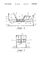
- FIG. 6 is a right side view of a hospital type bed incorporating a modified form of the present power module assembly
- FIG. 7 is rear view of the hospital bed illustrated in FIG. 5;
- FIG. 8 is a perspective view of a further alternative of the power module similar to FIG. 3 except adapted for manual override;
- FIG. 9 is top fragmentary view of the gearing in the power module illustrated in FIG. 8 showing the manual override gearing.
- a power module 10 according to the present invention is shown attached to a central section of a mattress support assembly 12 that includes hingedly interconnected wood panels including back panel 14, central stationary panel 15, thigh panel 16 and foot panel 17.
- the mattress support assembly 12 is adapted to provide the lower support for a mattress 20 that typically would be somewhat thinner and more flexible than a conventional mattress to accommodate the articulation of the mattress support assembly 12.
- the mattress 20 could itself include hinge elements along lines 22, 23 and 24 although the mattress itself forms no part of the present invention.
- the mattress support assembly 12, along with the power module assembly 10, is adapted to drop into and fit within side rails 26 and 27 of a standard mattress frame 28.
- side rails 26 and 27 conventionally are formed from angle iron include a horizontal portion 30 and a vertical portion 31.
- the mattress support panels 14, 15, 16 and 17 have a width slightly less than the inside width of the vertical frame member portion 31 and rest on the horizontal frame member portions 30.
- the foot panel 17 carries links 33 that are pivotally connected at 34 to the side rails 26 and 27 of the bed frame 28.
- the panels 14, 15, 16 and 17 of the mattress support assembly 12 are preferably formed of plywood or other suitable composite board both because of their low cost and because furniture manufactures are skilled in handling such materials.
- Back panel 14 is pivotally hinged to central panel 15 (which is stationary in frame 28) by hinges 36
- leg panel 16 is pivotally hinged to central panel 15 by hinges 37
- foot panel 17 is pivotally hinged to leg or thigh panel 16 by hinges 39.
- the power module 10 is more clearly illustrated in FIGS. 3, 4 and 5, and as seen in FIG. 3 the power module 10 includes an elongated rectangular housing having a bottom wall 42 a top wall 43 and side walls 44 and 45. These walls are formed from aluminum extrusions.
- the top wall 43 has flanges 46 and 47 that carry a plurality of bosses 49 that receive fasteners to connect the housing and the entire power module 10 to the lower surface of the central stationary seat panel 15 as illustrated in FIG. 2.
- the side walls 44 and 45 support outwardly projecting electric motors assemblies 51 and 52 which power respectively the leg panel 16 and the head panel 14 in the mattress support 12.
- Motors 51 and 52 are controlled by a control system 55 that closes a forward opening 56 in the housing and has a remote switch assembly 57 that has separate switches 58 and 59 for reversely controlling the motors 51 and 52.
- rocker shaft 62 drives rear rocker shaft 62 while motor 52 drives forward rocker shaft 63.
- the rocker shafts 62 and 63 have rocker arms 65, 66, 67 and 68 connected at their outboard ends, each of which has a nylon roller 70, constructed for example of "Delrin" carried by a short axial shaft 71.
- Each of the motors 51 and 52 drives its associated rocker shaft 62, 63 in oscillating motion through reducing worm and worm wheel gearing assembly 74 illustrated in FIGS. 4 and 5 which is identical for both motors although gearing 74 is illustrated in these FIGS. in connection with the forward rocker shaft 63.
- motor output shaft 76 carries a worm gear 77 that interengages with a worm wheel 79 that is shafted with another worm gear 81 that interengages with a worm wheel 83 fixed to rocker shaft 63.
- This double reduction gearing provides a gearing 74 with high reduction characteristics on the order of a 3600 to 1 RPM reduction between motor output shaft 76 and rocker shaft 63, bearing in mind that rocker shaft 63 oscillates less than a quarter of a revolution in moving head planar member 14 from its horizontal position to its fully upright position illustrated approximately in FIG. 1, and similar parameters are utilized for the rear or leg rocker shaft 62.
- rocker shafts 62 and 63 are rotatably supported in bearings carried by housing side walls 44, 45 and no other outboard means of support are provided for these rocker shafts 62 and 63.
- the power module 10 may be shipped as a unit to either the bed manufacturer or to the ultimate user without requiring any assembly to an outer frame commonly thought necessary in the prior art.
- FIGS. 6 to 9 A modified power module 110 is illustrated in FIGS. 6 to 9 in connection with a hospital type articulated bed 112.
- Bed 112 includes a head assembly 115 consisting of a rectangular carriage 116 vertically slidable on posts 117, and a foot assembly 120 including an upper rectangular carriage 121 slidable on stationary tubular posts 122.
- the foot assembly 120 is illustrated FIG. 7 it should be understood head assembly 115 is generally similar although somewhat larger.
- Bed assembly 112 includes a rigid rectangular frame 126 that moves vertically upwardly and downwardly as a unit with power module 110 by means of forward and rear cross-frames 127 and 128 that are threadedly carried by vertical screws 130. Screws 130 are rotated by universal drive shafts 132 and 133 by an additional motor 135 seen in FIGS.
- FIG. 6 the power module 110 is supported on a mattress support assembly 145 similar to support 12 illustrated in connection FIGS. 1 to 2 except a heavier duty version to accommodate the hospital environment.
- mattress support assembly 145 includes a head panel 150, central panel 151, side panel 152 and leg panel 153. The rear end of panel 153 is linked to frame 126 by pivotal bars 155.
- the power module 137 includes a first electric motor 157 adapted to pivot the forward rocker shaft 158 and a rear electric motor 159 adapted to pivot rear rocker shaft 161.
- Both rocker shafts 158 and 161 carry rocker arms 163 with nylon rollers 165 at their distal ends in the same way as described above with respect to the in FIGS. 1 and 2 embodiment.
- Motors 157 and 159 are reversely controlled by remote control 165 associated with control 140.
- Housing 110 is somewhat wider than housing 41 in FIG. 3 to accommodate the parallel pinion reducing gear assembly 170 shown mounted between housing side walls 171 and 172.
- Gearing 170 is the same for both motors 157 and 159 and is shown in connection with motor 157 in FIG. 9, which as described above pivots rocker shaft 158.
- Gearing 170 is essentially a five stage reduction gearing including motor output shaft 173 engaging reducing pinion pair 174 on idler shaft 175 interengaging a reducing pinion pair 177 rotatably mounted on idler shaft 178 in turn engaging reducing pinion 180 on idler shaft 175, that engages reducing pinion gear 182 on idler shaft 178 which engages reducing pinion pair 184 on idler shaft 175 finally engaging enlarged pinion gear 186 fixedly carried by rocker shaft 158.
- the power module 110 is similar to that described above in connection with FIGS. 1 to 3.
Abstract
Description
Claims (13)
Priority Applications (2)
| Application Number | Priority Date | Filing Date | Title |
|---|---|---|---|
| US07/597,525 US5063623A (en) | 1990-10-15 | 1990-10-15 | Power module for an ariculated bed |
| US09/108,768 US6061852A (en) | 1990-10-15 | 1998-07-02 | Power integrated articulated inner spring-mattress |
Applications Claiming Priority (1)
| Application Number | Priority Date | Filing Date | Title |
|---|---|---|---|
| US07/597,525 US5063623A (en) | 1990-10-15 | 1990-10-15 | Power module for an ariculated bed |
Related Child Applications (1)
| Application Number | Title | Priority Date | Filing Date |
|---|---|---|---|
| US08/308,412 Continuation-In-Part US5568661A (en) | 1990-10-15 | 1994-09-19 | Articulated bed with frame mounted power module |
Publications (1)
| Publication Number | Publication Date |
|---|---|
| US5063623A true US5063623A (en) | 1991-11-12 |
Family
ID=24391895
Family Applications (1)
| Application Number | Title | Priority Date | Filing Date |
|---|---|---|---|
| US07/597,525 Expired - Lifetime US5063623A (en) | 1990-10-15 | 1990-10-15 | Power module for an ariculated bed |
Country Status (1)
| Country | Link |
|---|---|
| US (1) | US5063623A (en) |
Cited By (45)
| Publication number | Priority date | Publication date | Assignee | Title |
|---|---|---|---|---|
| US5245718A (en) * | 1992-10-09 | 1993-09-21 | Joerns Healthcare, Inc. | Adjustable bed with single actuator |
| EP0568957A1 (en) * | 1992-05-04 | 1993-11-10 | Vg S.A. | Actuator assembly, particularly for articulated hospital beds |
| EP0604240A1 (en) * | 1992-12-25 | 1994-06-29 | Paramount Bed Company Limited | A base structure for a bed |
| US5544376A (en) * | 1994-01-31 | 1996-08-13 | Maxwell Products, Inc. | Articulated bed with customizable remote control |
| US5579550A (en) * | 1994-09-19 | 1996-12-03 | C.E.B. Enterprises, Inc. | Articulated bed with collapsible frame |
| US5608932A (en) * | 1994-05-02 | 1997-03-11 | France Bed Co., Ltd. | Articulated bed apparatus |
| US5675849A (en) * | 1995-02-17 | 1997-10-14 | Koch; Dietmar | Drive for adjustable parts of recliners or beds |
| US6008598A (en) * | 1998-04-22 | 1999-12-28 | Patmark Company, Inc. | Hand-held controller for bed and mattress assembly |
| US6088853A (en) * | 1997-05-23 | 2000-07-18 | Thomas Beteiligungs-Und Vermogens Gmbh & Co. Kg | Slatted base, in particular for a bed |
| US6106576A (en) * | 1994-07-19 | 2000-08-22 | Maxwell Products, Inc. | Adjustable massage bed assembly with handheld control unit having automatic stop safety feature |
| US6163904A (en) * | 1998-12-08 | 2000-12-26 | Everett Associates, Inc. | Articulated table for supporting a person |
| WO2001045536A3 (en) * | 1999-12-23 | 2001-12-27 | Cimosys Ag | Motor-driven, adjustable supporting device for the upholstery of seating and/or reclining furniture, for example of a mattress or of a bed |
| US6679555B2 (en) * | 2000-09-22 | 2004-01-20 | Christian Bangert | Adjusting device for a piece of furniture on which to lie or for sitting on with at least one swivel part that is pivotally attached, by way of a torsion bar, to said piece of furniture on which to lie or for sitting on |
| US6742205B2 (en) | 1999-12-23 | 2004-06-01 | Cimosys Ag | Adjustable padding device for a piece of furniture used for sitting and/or lying upon |
| US6763536B2 (en) | 2000-04-11 | 2004-07-20 | Cimosys Ag | Motor adjustable support device for the upholstery of a piece of furniture that is used for sitting and/or laying upon |
| US20040169408A1 (en) * | 2001-08-08 | 2004-09-02 | Eckhart Dewert | Furniture drive for displacing components of a piece of furniture relative to one another |
| WO2004100723A1 (en) * | 2003-05-16 | 2004-11-25 | Hilding Anders International Ab | Articulated bed |
| US6826793B2 (en) | 2003-02-05 | 2004-12-07 | Daniel R. Tekulve | Articulating bed frame |
| US20040262587A1 (en) * | 2001-11-26 | 2004-12-30 | Eckhart Dewert | Electromotive furniture drive for displacing parts of an item of furniture in relation to one another |
| US20050144720A1 (en) * | 2004-01-06 | 2005-07-07 | Stephan Poulin | Side rail, hospital bed including the same, method of operating associated thereto and kit for assembling the side rail |
| US6961971B2 (en) | 1999-12-23 | 2005-11-08 | Cimosys Ag | Motor adjustable support device for the upholstery of a seat and/or reclining furniture |
| US20050251917A1 (en) * | 2004-05-12 | 2005-11-17 | Wall Daniel P Sr | Ups shippable adjustable articulating bed |
| US20060000022A1 (en) * | 2003-01-15 | 2006-01-05 | Eckhart Dewert | Adjustable piece of seating furniture |
| US20060058587A1 (en) * | 2004-09-10 | 2006-03-16 | Heimbrock Richard H | Wireless control system for a patient-support apparatus |
| US20060130236A1 (en) * | 2003-06-05 | 2006-06-22 | Eckhart Dewert | Modular system for assembling a motorized adjustable support apparatus for the upholstery of furniture for sitting and/or lying |
| EP1698257A1 (en) * | 2005-03-04 | 2006-09-06 | Flex Equipos De Descanso, S.A. | Articulated box with motor |
| US20060260054A1 (en) * | 2004-12-23 | 2006-11-23 | Lubbers David P | Wireless control system for a patient support apparatus |
| US7331557B2 (en) * | 2000-09-21 | 2008-02-19 | Linak A/S | Furniture drive embodied as a double drive |
| WO2008027906A2 (en) * | 2006-08-30 | 2008-03-06 | Select Comfort Corporation | Bed foundation with drop-in unit |
| US20090019640A1 (en) * | 2007-07-18 | 2009-01-22 | L&P Property Management Company | Adjustable Bed Having Movable Frame |
| US7484257B2 (en) | 2002-07-10 | 2009-02-03 | Cimosys Ag | Electromechanical furniture drive mechanism |
| US20090235456A1 (en) * | 2006-05-26 | 2009-09-24 | Klaus Bock | Pivoting Device |
| US20140345059A1 (en) * | 2013-05-27 | 2014-11-27 | Logicdata Electronic & Software Entwicklungs Gmbh | Arrangement for adjusting a bed, particularly a head section and foot section of the bed, as well as drive unit |
| CN104398051A (en) * | 2014-10-27 | 2015-03-11 | 王胜根 | Ultrathin electric adjustable bed |
| US20150143934A1 (en) * | 2013-11-28 | 2015-05-28 | Timotion Technology Co., Ltd. | Linear actuator |
| US9198520B2 (en) | 2009-03-11 | 2015-12-01 | Aaron Goldsmith | Modular user-assembled adjustable, and high-low adjustable beds |
| US9248066B2 (en) * | 2013-09-17 | 2016-02-02 | Panasonic Intellectual Property Management Co., Ltd. | Wheelchair and combined bed |
| CN106388355A (en) * | 2015-07-28 | 2017-02-15 | 斯泰必鲁斯股份有限公司 | Piece of furniture and adjusting assembly, in particular for adjusting a back of a chair |
| US9713388B2 (en) | 2009-03-11 | 2017-07-25 | Aaron Goldsmith | Modular user-assembled adjustable, and high-low adjustable beds |
| CN107440379A (en) * | 2016-04-29 | 2017-12-08 | 德韦特集团 | Electronic double-drive device |
| US20180008049A1 (en) * | 2016-07-06 | 2018-01-11 | Chuan-Hang Shih | Frame of electric bed |
| EP3238573A3 (en) * | 2016-04-29 | 2018-02-14 | De Werth Group AG | Electric motor double drive |
| US20190191890A1 (en) * | 2017-12-27 | 2019-06-27 | Apex Health Care Mfg. Inc. | Electric Bed with Independent Adjusting Device for Waist Rest |
| CN112618202A (en) * | 2020-12-31 | 2021-04-09 | 重庆理工大学 | Nursing sickbed with turning function and using method thereof |
| US20240023720A1 (en) * | 2022-07-21 | 2024-01-25 | Chuan-Hang Shih | Electric bed |
Citations (10)
| Publication number | Priority date | Publication date | Assignee | Title |
|---|---|---|---|---|
| US3073635A (en) * | 1959-07-17 | 1963-01-15 | Edward J Schaefer | Shaft coupling |
| CA667395A (en) * | 1963-07-23 | The Hard Manufacturing Company | Bed construction | |
| US3245092A (en) * | 1963-10-08 | 1966-04-12 | U S Naval Hospital | Adjustable bedboard |
| US3300794A (en) * | 1965-04-23 | 1967-01-31 | Altorfer Hans | Bedstead |
| US3921230A (en) * | 1973-05-25 | 1975-11-25 | Robert Hanning | Apparatus for raising the end of a bed mattress |
| US4005497A (en) * | 1974-07-12 | 1977-02-01 | Hermann Lanz Ag, Switzerland | Supporting plate arrangement |
| US4094024A (en) * | 1976-08-30 | 1978-06-13 | Interroyal Corporation | System for controlling relative movement of portions of a bed |
| US4120057A (en) * | 1976-05-21 | 1978-10-17 | Hanning Elektro-Werke Robert Hanning | Electromechanical adjusting device |
| US4271545A (en) * | 1979-07-30 | 1981-06-09 | Christian Iii Fredrick W | Adapter for adjustable hospital beds |
| US4463463A (en) * | 1980-03-28 | 1984-08-07 | Aisin Seiki Kabushiki Kaisha | Adjustable bed |
-
1990
- 1990-10-15 US US07/597,525 patent/US5063623A/en not_active Expired - Lifetime
Patent Citations (10)
| Publication number | Priority date | Publication date | Assignee | Title |
|---|---|---|---|---|
| CA667395A (en) * | 1963-07-23 | The Hard Manufacturing Company | Bed construction | |
| US3073635A (en) * | 1959-07-17 | 1963-01-15 | Edward J Schaefer | Shaft coupling |
| US3245092A (en) * | 1963-10-08 | 1966-04-12 | U S Naval Hospital | Adjustable bedboard |
| US3300794A (en) * | 1965-04-23 | 1967-01-31 | Altorfer Hans | Bedstead |
| US3921230A (en) * | 1973-05-25 | 1975-11-25 | Robert Hanning | Apparatus for raising the end of a bed mattress |
| US4005497A (en) * | 1974-07-12 | 1977-02-01 | Hermann Lanz Ag, Switzerland | Supporting plate arrangement |
| US4120057A (en) * | 1976-05-21 | 1978-10-17 | Hanning Elektro-Werke Robert Hanning | Electromechanical adjusting device |
| US4094024A (en) * | 1976-08-30 | 1978-06-13 | Interroyal Corporation | System for controlling relative movement of portions of a bed |
| US4271545A (en) * | 1979-07-30 | 1981-06-09 | Christian Iii Fredrick W | Adapter for adjustable hospital beds |
| US4463463A (en) * | 1980-03-28 | 1984-08-07 | Aisin Seiki Kabushiki Kaisha | Adjustable bed |
Cited By (72)
| Publication number | Priority date | Publication date | Assignee | Title |
|---|---|---|---|---|
| EP0568957A1 (en) * | 1992-05-04 | 1993-11-10 | Vg S.A. | Actuator assembly, particularly for articulated hospital beds |
| USRE35201E (en) * | 1992-10-09 | 1996-04-09 | Krauska; Bernard J. | Adjustable bed with single actuator |
| US5245718A (en) * | 1992-10-09 | 1993-09-21 | Joerns Healthcare, Inc. | Adjustable bed with single actuator |
| EP0604240A1 (en) * | 1992-12-25 | 1994-06-29 | Paramount Bed Company Limited | A base structure for a bed |
| US5544376A (en) * | 1994-01-31 | 1996-08-13 | Maxwell Products, Inc. | Articulated bed with customizable remote control |
| US5600214A (en) * | 1994-01-31 | 1997-02-04 | Maxwell Products, Inc. | User-controllable adjustable massage bed |
| US5608932A (en) * | 1994-05-02 | 1997-03-11 | France Bed Co., Ltd. | Articulated bed apparatus |
| US6106576A (en) * | 1994-07-19 | 2000-08-22 | Maxwell Products, Inc. | Adjustable massage bed assembly with handheld control unit having automatic stop safety feature |
| US5579550A (en) * | 1994-09-19 | 1996-12-03 | C.E.B. Enterprises, Inc. | Articulated bed with collapsible frame |
| US5675849A (en) * | 1995-02-17 | 1997-10-14 | Koch; Dietmar | Drive for adjustable parts of recliners or beds |
| US6088853A (en) * | 1997-05-23 | 2000-07-18 | Thomas Beteiligungs-Und Vermogens Gmbh & Co. Kg | Slatted base, in particular for a bed |
| US6396224B1 (en) | 1998-04-22 | 2002-05-28 | Hill-Rom Services, Inc. | Hand-held controller for bed and mattress assembly |
| US6008598A (en) * | 1998-04-22 | 1999-12-28 | Patmark Company, Inc. | Hand-held controller for bed and mattress assembly |
| US6163904A (en) * | 1998-12-08 | 2000-12-26 | Everett Associates, Inc. | Articulated table for supporting a person |
| EP1410743A3 (en) * | 1999-12-23 | 2004-12-15 | Cimosys AG | Motor-driven, adjustable supporting device for the upholstery of seating and/or reclining furniture, for example of a mattress or of a bed |
| WO2001045536A3 (en) * | 1999-12-23 | 2001-12-27 | Cimosys Ag | Motor-driven, adjustable supporting device for the upholstery of seating and/or reclining furniture, for example of a mattress or of a bed |
| US6961971B2 (en) | 1999-12-23 | 2005-11-08 | Cimosys Ag | Motor adjustable support device for the upholstery of a seat and/or reclining furniture |
| US6742205B2 (en) | 1999-12-23 | 2004-06-01 | Cimosys Ag | Adjustable padding device for a piece of furniture used for sitting and/or lying upon |
| US6754922B2 (en) | 1999-12-23 | 2004-06-29 | Cimosys Ag | Motor-driven, adjustable supporting device for the upholstery of seating and/or reclining furniture, for example of a mattress or a bed |
| US6763536B2 (en) | 2000-04-11 | 2004-07-20 | Cimosys Ag | Motor adjustable support device for the upholstery of a piece of furniture that is used for sitting and/or laying upon |
| US7331557B2 (en) * | 2000-09-21 | 2008-02-19 | Linak A/S | Furniture drive embodied as a double drive |
| US6679555B2 (en) * | 2000-09-22 | 2004-01-20 | Christian Bangert | Adjusting device for a piece of furniture on which to lie or for sitting on with at least one swivel part that is pivotally attached, by way of a torsion bar, to said piece of furniture on which to lie or for sitting on |
| US20040169408A1 (en) * | 2001-08-08 | 2004-09-02 | Eckhart Dewert | Furniture drive for displacing components of a piece of furniture relative to one another |
| US8084966B2 (en) | 2001-11-26 | 2011-12-27 | Linak A/S | Electromotive furniture drive for displacing parts of an item of furniture in relation to one another |
| US20040262587A1 (en) * | 2001-11-26 | 2004-12-30 | Eckhart Dewert | Electromotive furniture drive for displacing parts of an item of furniture in relation to one another |
| US7484257B2 (en) | 2002-07-10 | 2009-02-03 | Cimosys Ag | Electromechanical furniture drive mechanism |
| US7198325B2 (en) | 2003-01-15 | 2007-04-03 | Deon Ag | Adjustable piece of seating furniture |
| US20060000022A1 (en) * | 2003-01-15 | 2006-01-05 | Eckhart Dewert | Adjustable piece of seating furniture |
| US7257850B1 (en) | 2003-02-05 | 2007-08-21 | Med-Mizer, Inc. | Articulating bed frame |
| US6826793B2 (en) | 2003-02-05 | 2004-12-07 | Daniel R. Tekulve | Articulating bed frame |
| US20070163046A1 (en) * | 2003-05-16 | 2007-07-19 | Rikard Eriksson | Articulated bed |
| WO2004100723A1 (en) * | 2003-05-16 | 2004-11-25 | Hilding Anders International Ab | Articulated bed |
| US7484254B2 (en) | 2003-05-16 | 2009-02-03 | Hilding Anders International Ab | Articulated bed |
| US20060130236A1 (en) * | 2003-06-05 | 2006-06-22 | Eckhart Dewert | Modular system for assembling a motorized adjustable support apparatus for the upholstery of furniture for sitting and/or lying |
| US7386901B2 (en) | 2003-06-05 | 2008-06-17 | Cimosys Ag | Modular system for assembling a motorized adjustable support apparatus for the upholstery of furniture for sitting and/or lying |
| US20050144720A1 (en) * | 2004-01-06 | 2005-07-07 | Stephan Poulin | Side rail, hospital bed including the same, method of operating associated thereto and kit for assembling the side rail |
| US7073219B2 (en) | 2004-01-06 | 2006-07-11 | Teknion Concept | Side rail, hospital bed including the same, method of operating associated thereto and kit for assembling the side rail |
| US20050251917A1 (en) * | 2004-05-12 | 2005-11-17 | Wall Daniel P Sr | Ups shippable adjustable articulating bed |
| US6990698B2 (en) | 2004-05-12 | 2006-01-31 | Wall Sr Daniel P | UPS shippable adjustable articulating bed |
| US20060058587A1 (en) * | 2004-09-10 | 2006-03-16 | Heimbrock Richard H | Wireless control system for a patient-support apparatus |
| US8125318B2 (en) | 2004-09-10 | 2012-02-28 | Hill-Rom Services, Inc. | Wireless control system for a patient-support apparatus |
| US8710950B2 (en) | 2004-12-23 | 2014-04-29 | Hill-Rom Services, Inc. | Wireless control system for a patient support apparatus |
| US20060260054A1 (en) * | 2004-12-23 | 2006-11-23 | Lubbers David P | Wireless control system for a patient support apparatus |
| EP1698257A1 (en) * | 2005-03-04 | 2006-09-06 | Flex Equipos De Descanso, S.A. | Articulated box with motor |
| US20090235456A1 (en) * | 2006-05-26 | 2009-09-24 | Klaus Bock | Pivoting Device |
| US8312579B2 (en) * | 2006-05-26 | 2012-11-20 | Hermann Bock Gmbh | Pivoting device |
| US20080052830A1 (en) * | 2006-08-30 | 2008-03-06 | Select Comfort Corporation | Bed foundation with drop-in unit |
| WO2008027906A3 (en) * | 2006-08-30 | 2008-04-24 | Select Comfort Corp | Bed foundation with drop-in unit |
| WO2008027906A2 (en) * | 2006-08-30 | 2008-03-06 | Select Comfort Corporation | Bed foundation with drop-in unit |
| US7530125B2 (en) * | 2007-07-18 | 2009-05-12 | L&P Property Management Company | Adjustable bed having movable frame |
| US20090019640A1 (en) * | 2007-07-18 | 2009-01-22 | L&P Property Management Company | Adjustable Bed Having Movable Frame |
| US10021989B2 (en) | 2009-03-11 | 2018-07-17 | Aaron Goldsmith | Modular user-assembled adjustable, and high-low adjustable beds |
| US9713388B2 (en) | 2009-03-11 | 2017-07-25 | Aaron Goldsmith | Modular user-assembled adjustable, and high-low adjustable beds |
| US9198520B2 (en) | 2009-03-11 | 2015-12-01 | Aaron Goldsmith | Modular user-assembled adjustable, and high-low adjustable beds |
| US9844274B2 (en) | 2009-03-11 | 2017-12-19 | Aaron Goldsmith | Modular user-assembled adjustable, and high-low adjustable beds |
| US9844273B2 (en) | 2009-03-11 | 2017-12-19 | Aaron Goldsmith | Modular user-assembled adjustable, and high-low adjustable beds |
| US20140345059A1 (en) * | 2013-05-27 | 2014-11-27 | Logicdata Electronic & Software Entwicklungs Gmbh | Arrangement for adjusting a bed, particularly a head section and foot section of the bed, as well as drive unit |
| US9248066B2 (en) * | 2013-09-17 | 2016-02-02 | Panasonic Intellectual Property Management Co., Ltd. | Wheelchair and combined bed |
| US9528580B2 (en) * | 2013-11-28 | 2016-12-27 | Timotion Technology Co., Ltd. | Linear actuator |
| US20150143934A1 (en) * | 2013-11-28 | 2015-05-28 | Timotion Technology Co., Ltd. | Linear actuator |
| CN104398051B (en) * | 2014-10-27 | 2016-08-24 | 王胜根 | Ultrathin electric is adjustable bed |
| CN104398051A (en) * | 2014-10-27 | 2015-03-11 | 王胜根 | Ultrathin electric adjustable bed |
| CN106388355A (en) * | 2015-07-28 | 2017-02-15 | 斯泰必鲁斯股份有限公司 | Piece of furniture and adjusting assembly, in particular for adjusting a back of a chair |
| US10219625B2 (en) * | 2015-07-28 | 2019-03-05 | Stabilus Gmbh | Piece of furniture and adjusting assembly, in particular for adjusting a back of a chair |
| CN106388355B (en) * | 2015-07-28 | 2019-08-09 | 斯泰必鲁斯股份有限公司 | Furniture and the adjustment component for being particularly used for adjustment backrest |
| EP3238573A3 (en) * | 2016-04-29 | 2018-02-14 | De Werth Group AG | Electric motor double drive |
| CN107440379A (en) * | 2016-04-29 | 2017-12-08 | 德韦特集团 | Electronic double-drive device |
| US20180008049A1 (en) * | 2016-07-06 | 2018-01-11 | Chuan-Hang Shih | Frame of electric bed |
| US20190191890A1 (en) * | 2017-12-27 | 2019-06-27 | Apex Health Care Mfg. Inc. | Electric Bed with Independent Adjusting Device for Waist Rest |
| US10786087B2 (en) * | 2017-12-27 | 2020-09-29 | Apex Health Care Mfg. Inc. | Electric bed with independent adjusting device for waist rest |
| CN112618202A (en) * | 2020-12-31 | 2021-04-09 | 重庆理工大学 | Nursing sickbed with turning function and using method thereof |
| US20240023720A1 (en) * | 2022-07-21 | 2024-01-25 | Chuan-Hang Shih | Electric bed |
Similar Documents
| Publication | Publication Date | Title |
|---|---|---|
| US5063623A (en) | Power module for an ariculated bed | |
| US5568661A (en) | Articulated bed with frame mounted power module | |
| US8091165B2 (en) | Modular bedding system including modular bed base | |
| US5090071A (en) | Transportable and foldable articulated bed | |
| US5303437A (en) | Multi-function and automatic sick bed | |
| US5438723A (en) | Collapsible bed and panel hinge | |
| US6990698B2 (en) | UPS shippable adjustable articulating bed | |
| US6230344B1 (en) | Adjustable bed | |
| US6951037B2 (en) | Universal adjustable bed | |
| US6061852A (en) | Power integrated articulated inner spring-mattress | |
| US5640730A (en) | Adjustable articulated bed with tiltable head portion | |
| US3593350A (en) | Retractable bed | |
| US7093312B2 (en) | Single motor adjustable bed | |
| US7530125B2 (en) | Adjustable bed having movable frame | |
| US4381571A (en) | Adjustable articulated bed | |
| US4361917A (en) | Portable orthopedic bed | |
| JP2001511380A (en) | Bed frame with articulation | |
| US20090178201A1 (en) | Adjustable Bed Having Movable Lumbar Support | |
| US5790993A (en) | Automatic futon frame | |
| US5566412A (en) | Inclinable bed frame assembly | |
| US3991428A (en) | Articulated bed | |
| US4974271A (en) | Mounting apparatus for wall beds | |
| US6138299A (en) | Automatic futon frame | |
| JP3352320B2 (en) | Wake-up bed equipment | |
| US5785183A (en) | Display unit and arrangement of this display unit in premises furnished with an opening |
Legal Events
| Date | Code | Title | Description |
|---|---|---|---|
| AS | Assignment |
Owner name: C.E.B. ENTERPRISES, INC., 407 HAWLEY ROAD, MUNDELE Free format text: ASSIGNMENT OF ASSIGNORS INTEREST.;ASSIGNOR:CHIZCK, MICHAEL W.;REEL/FRAME:005494/0369 Effective date: 19900921 Owner name: C.E.B. ENTERPRISE, INC., 407 HAWLEY ROAD, MUNDELEI Free format text: ASSIGNMENT OF ASSIGNORS INTEREST.;ASSIGNOR:BATHRICK, LEELAND M.;REEL/FRAME:005494/0367 Effective date: 19900921 Owner name: C.E.B. ENTERPRISES, INC., 407 HAWLEY ROAD, MUNDELE Free format text: ASSIGNMENT OF ASSIGNORS INTEREST.;ASSIGNOR:BRITTAIN, GLENN;REEL/FRAME:005494/0371 Effective date: 19900921 |
|
| STCF | Information on status: patent grant |
Free format text: PATENTED CASE |
|
| REMI | Maintenance fee reminder mailed | ||
| FPAY | Fee payment |
Year of fee payment: 4 |
|
| SULP | Surcharge for late payment | ||
| FPAY | Fee payment |
Year of fee payment: 8 |
|
| FPAY | Fee payment |
Year of fee payment: 12 |
|
| SULP | Surcharge for late payment |
Year of fee payment: 11 |