US5063451A - Hand held recording apparatus with window on lower body portion for viewing recording position - Google Patents
Hand held recording apparatus with window on lower body portion for viewing recording position Download PDFInfo
- Publication number
- US5063451A US5063451A US07/375,981 US37598189A US5063451A US 5063451 A US5063451 A US 5063451A US 37598189 A US37598189 A US 37598189A US 5063451 A US5063451 A US 5063451A
- Authority
- US
- United States
- Prior art keywords
- recording
- recording apparatus
- recording medium
- head
- lower body
- Prior art date
- Legal status (The legal status is an assumption and is not a legal conclusion. Google has not performed a legal analysis and makes no representation as to the accuracy of the status listed.)
- Expired - Lifetime
Links
Images


Classifications
-
- B—PERFORMING OPERATIONS; TRANSPORTING
- B41—PRINTING; LINING MACHINES; TYPEWRITERS; STAMPS
- B41J—TYPEWRITERS; SELECTIVE PRINTING MECHANISMS, i.e. MECHANISMS PRINTING OTHERWISE THAN FROM A FORME; CORRECTION OF TYPOGRAPHICAL ERRORS
- B41J3/00—Typewriters or selective printing or marking mechanisms characterised by the purpose for which they are constructed
- B41J3/36—Typewriters or selective printing or marking mechanisms characterised by the purpose for which they are constructed for portability, i.e. hand-held printers or laptop printers
Definitions
- This invention relates to a recording apparatus which is capable of recording images such as characters, figures or video images on a recording medium such as plain paper, worked paper or a plastic sheet for OHP.
- Various types of recording apparatuses for recording images such as characters and figures have heretofore been developed. They include, for example, a so-called serial printer in which a recording head effects recording while moving relative to a recording sheet, a so-called line printer in which recording is effected on a recording sheet being conveyed by a line-shaped recording head, and a so-called handy printer in which the apparatus body having a recording head is manually scanned relative to a recording sheet to thereby effect recording.
- the recording positioning when these recording apparatuses effect recording is accomplished, for example, in the serial printer or the line printer, by causing the end portion of a recording sheet to bear against a guide member provided with a predetermined position as a reference and setting the recording sheet, or by inputting an image signal so as to correspond to a recording position.
- recording positioning marks a, b and c are usually provided on the apparatus body and the design is such that when the apparatus body is scanned in the direction of arrow I, recording is effected between the marks a and b and recording is started from the mark c.
- the handy printer can effect recording on a notebook or the like, but because of the manual scanning, the image may sometimes deviate in the direction of scanning and there is the possibility that it is difficult to record the same image accurately. Also, as regards the recording positioning, the actual recording position cannot be looked at squarely, and this leads to the problem that skill is required for accomplishing highly accurate positioning.
- the prior-art handy printer can accomplish recording with the amount of movement thereof relative to the recording sheet by manual scanning detected because the recording information is characters and accordingly the recording density is 8 pels or less, but in the case of an image (256 ⁇ 256 picture elements) in which the recording information is of the order of 16 pels, the recording density becomes higher and the recording width also becomes wider and therefore, there has been the problem that irregularity of recording scan is liable to occur and the image may be deteriorated.
- FIG. 1 is a schematic perspective view showing a recording apparatus according to a first embodiment of the present invention.
- FIG. 2 illustrates a state in which an upper jaw portion is opened.
- FIG. 3 is an illustration of a recording head.
- FIG. 4 is a block diagram of a control system.
- FIG. 5 is a flow chart of the control procedure.
- FIG. 6 is a recording timing chart.
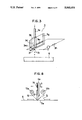
- FIG. 7 is an illustration of a second embodiment of the present invention.
- FIG. 8 is an illustration of a recording head according to the second embodiment.
- FIG. 9 is an illustration of another embodiment of the positioning portion.
- FIGS. 10A-10C are illustrations showing other embodiments of the opening-closing mechanism for the upper jaw portion and the lower jaw portion.
- FIG. 11 is an illustration of the prior art.
- recording positioning can be accomplished easily and reliably by setting the apparatus on a recording medium while visually comfirming a positioning portion indicative of a recording area.
- recording means can be automatically scanned by scanning means to thereby effect predetermined recording and therefore, even for the same image, an image of high accuracy which is free of image deviation can be obtained stably and further, recording becomes possible also on various recording mediums such as notebooks and the like.
- FIG. 1 is a schematic perspective view of the entire recording apparatus, and FIG. 2 illustrates a state in which the apparatus is opened.
- the apparatus body is constructed so that an upper jaw portion 1 and a lower jaw portion 2 are openable, and a recording head 3 providing recording means and scanning means 4 for the head 3 are provided in the upper jaw portion 1, and a positioning portion 5 is provided in the lower jaw portion 2.
- the positioning portion 5 is designed such that it can be visually confirmed when the upper jaw portion 1 is opened. Accordingly, by opening the upper jaw portion 1 and visually confirming the positioning portion 5 when the apparatus body is placed on a recording medium 6, the recording position can be confirmed. Design is also made such that when the upper jaw portion 1 is closed after positioning, an image is automatically recorded on the positioning portion of the recording medium 6.
- the upper jaw portion 1 is formed into a box-like shape
- the lower jaw portion 2 is formed into a plate-like shape.
- the upper jaw portion 1 and the lower jaw portion 2 are pivotally connected together at an end portion thereof by a shaft 7, and the two portions are constructed so as to be openable and closable like the mouth of an alligator.
- a spring 8 is mounted on the shaft 7 and biases the upper jaw portion 1 and the lower jaw portion 2 in a direction to open them (the direction of arrow A in FIG. 2). Further, a stop 9 is formed on the upper jaw portion 1 and the lower jaw portion 2 so that when the upper jaw portion 1 is opened, it is pivotally moved in the direction of arrow A by the action of the spring 8 and that by the stop 9, the upper jaw portion 1 maintains its open state at a predetermined angle with respect to the lower jaw portion 2.
- the upper jaw portion 1 can be closed by being pushed in the direction of arrow B in FIG. 2 against the biasing force of the spring 8, and there is provided a sensor 10 for detecting the closed state at this time.
- the closed state of the upper jaw portion 1 and the lower jaw portion 2 is maintained by a resilient restraining portion 2a which is provided on the lower jaw portion 2 being engaged with the recess 1a of the upper jaw portion 1.
- the sensor 10 is comprised of a light-intercepting plate 10a projectedly provided on the open end portion of the upper jaw portion 1, and a photointerrupter 10b provided on the open end portion of the lower jaw portion 2, and design is made such that when the upper jaw portion 1 is closed, the light-intercepting plate 10a intercepts the light of the photointerrupter 10b, whereby the opened or closed state of the upper jaw portion 1 and the lower jaw portion 2 may be detected.
- the recording head 3 which is the recording means.
- the recording head 3 is a so-called ink jet type recording head as shown in FIG. 3, and this head 3 has a recording density of 16 dots/mm in the main scanning direction and is multi-nozzled for 256 dots.
- the principle of this head is as follows. Ink 3c is introduced from an ink inlet tube 3a into an ink liquid chamber 3b. There the expansion of the liquid or the production of a bubble is caused by the pulse-like heat generation of a heat generating member 3d provided in the liquid chamber 3b upon the supply of electric power through electrodes 3e 1 and 3e 2 .
- the ink 3c is discharged and flies as a small droplet from an orifice 3f and adheres to the recording medium 6, whereby recording is accomplished.
- the heat generating member 3d is provided on a base plate 3g, and the voltage of a power source 3h is applied thereto in accordance with an input signal which will be described later, whereby the heat generating member 3d is heated in conformity with the input signal and the ink 3c flies to the recording medium 6 in conformity with said heating.
- the scanning means 4 for scanning the recording head 3 is constructed as shown in FIG. 1.
- the recording head 3 is mounted on a head mounting plate 4a, and two guide shafts 4b mounted on the upper jaw portion 1 are inserted into the vicinity of the opposite end portions of the head mounting plate 4a. Accordingly, the head mounting plate 4a is slidable in the directions of arrows C and D along the guide shafts 4b.
- a female screw 4c is provided at a predetermined location on the head mounting plate 4a, and a male screw 4d is threadably engaged with the female screw 4c.
- This male screw 4d is rotatably but immovably mounted on the upper jaw portion 1, and a gear 4e is secured to the vicinity of the end of the male screw, and is connected to a scan motor 4g through a motor gear 4f.
- the scan motor 4g revolves in the forward direction or the reverse direction
- the male screw 4d is rotated and by the rotation thereof, the head mounting plate 4a slides in the direction of arrow C or the direction of arrow D, whereby the recording head 3 scans in the sub-scanning direction.
- an encoder 4h for detecting the amount of rotation of the male screw 4d.
- This encoder 4h has a disc-like encode plate 4h 1 mounted on the end portion of the male screw 4d and adapted to rotate with the rotation of the male screw 4d.
- Slits 4h 2 are provided at equal intervals in the outer periphery of the encode plate 4h 1 , and a photointerrupter 4h 3 is provided in opposed relationship with one of these slits 4h 2 .
- the encode plate 4h 1 is rotated by the rotation of the male screw 4d, the slits 4h 2 switch the photointerrupter 4h 3 , and the amount of sub-scanning of the recording head 3 is detected by the output pulse of the photointerrupter 4h 3 and said amount of sub-scanning is controlled by a control system which will be described later.
- photointerrupters 4i and 4j are mounted at predetermined positions on the upper jaw portion 1, i.e., the home position of the recording head 3 and the reverse position after the head 3 has been moved in the direction of arrow C.
- a light-intercepting plate 4k formed integrally with the head mounting plate 4a intercepts the lights of the photointerrupters 4i and 4j and the scanning range of the recording head 3 is controlled by the signals from the photointerrupters 4i and 4j.
- the positioning portion 5 will now be described.
- a square recording window 5a is formed at a predetermined location on the lower jaw portion 2.
- This recording window 5a is of a size somewhat larger than the size of the image recorded by the recording head 3, and a square-shaped transparent window 5b formed of a transparent substance such as transparent resin or transparent glass is formed around the recording window 5a.
- a positioning mark 5c such as a tape or a colored substance such as a paint is formed on the peripheral edge of the transparent window 5b. The portion surrounded by this positioning mark 5c is the recording area to be recorded on the recording medium by the recording head 3, and can be visually confirmed when the upper jaw portion 1 is opened as shown in FIG. 2.
- the operator carries the apparatus body and places it on the recording medium 6.
- the upper jaw portion 1 is in a state in which its mouth is opened by the spring 8. Accordingly, the recording window 5a can be visually confirmed, and the positioning mark 5c of the recording window 5a is registered with a location on the recording medium at which recording is to be effected.
- the scan motor 4g By the closing of the recording switch, the scan motor 4g is driven and the recording head 3 is scanned in the direction of arrow C in FIG. 1. At this time, the slits 4h 2 of the encode plate 4h 1 are counted by the photointerrupter 4h 3 , and after a predetermined number has been counted, that is, after the recording head 3 has come into the positioning mark 5c, the recording head 3 effects recording on each line in confirmity with an image signal.
- This image signal is supplied from an information producing apparatus, not shown, such as a document reader, a personal computer or a word processor, or an outside information source such as a facsimile apparatus, a television set or a video apparatus.
- an information producing apparatus such as a document reader, a personal computer or a word processor, or an outside information source such as a facsimile apparatus, a television set or a video apparatus.
- the recording of one line is effected in synchronism with the count number of the encoder 4h, and this recording is effected in the sub-scanning direction by a predetermined distance, in the case of the present embodiment, 16 mm, whereupon the recording of one line is completed. Accordingly, the image obtained by this recording is an image of a size 16 mm ⁇ 16 mm (256 ⁇ 256 dots).
- the recording head 3 upon completion of said recording, the recording head 3 is positioned within the positioning mark 5c of the recording window 5a.
- the recording head 3 When said recording is completed, the recording head 3 is further scanned in the direction of arrow C in FIG. 1, and when the light-intercepting plate 4k revolves in the reverse direction and the recording head 3 is scanned in the direction of arrow D in FIG. 1.
- the scan motor 4g When the light-intercepting plate 4k switches the photointerrupter 4i, the scan motor 4g is stopped and the recording head 3 is stopped at the home position.
- a video signal reproduced from a video recorder or an integral type video camera or the like or an ordinary television signal is input as NTSC signal to a video input terminal 50, and upon change-over of a video switch 51, it can be monitored by an outside monitor (for example, a TV receiver).
- the NTSC signal is input to a signal processing circuit 52 for receiving the NTSC composite signal as an input, extracting a synchronizing signal and an image luminance signal and analog/digital-converting the same.
- This circuit 52 is operated by the control of a timing control unit 54 controlled and actuated by a CPU 53, and the output thereof is memorized as an 8-bit density signal in a multivalued data buffer RAM 55 (in the present embodiment, memorization of 265 ⁇ 256 picture elements of the substantially central portion of one frame screen is effected).
- said memorizing operation is stopped by the depression of the image freeze switch of a console unit 56, and the CPU 53 executes a binarizing process to record said memorized image data in accordance with the program of an ROM 57 storing therein a microprogram which will be described later, and stores said binarized image data again into a binary data buffer RAM 58.
- This binary signal is again converted into the NTSC composite signal by a digital/analog conversion signal processing circuit 59, and upon change-over of the video switch 51, the operator can confirm the recorded image by a monitor.
- the operation of the image freeze switch is performed by the operator at a desired time.
- the aforedescribed recording apparatus is connected as a printer unit 60 to the CPU 53, and when the CPU 53 discriminates the light interception of the photointerrupter 10b by the depression of the upper jaw portion 1, recording is started.
- the binarizing process for example, the simple binarization by a predetermined threshold value prepared in ROM 57, the binarizing process extracting the outline portion, or the pseudo-intermediate tone process typified by the dither method or the error diffusion method can be selected by the instructions of the console unit 56.
- step S1 the depression of the video changeover switch of the console unit 56 is detected, and with the depression of this switch, the program branches off to step S2, and the video switch 51 for outputting one of the outside video signal and the binary video signal binarized in the recording apparatus to the outside monitor is switching-controlled.
- step S3 the depression of the image freeze switch of the console unit 56 adapted to be depressed when a desired record image is obtained from the monitor screen is detected, and at step S4, the multivalued data buffer RAM 55 of FIG. 5 is accessed for each picture element by the CPU 53 in accordance with a desired binarizing program as previously described, and after the binarization, the result is stored in the binary data buffer RAM 58.
- step S5 After said operation is processed by an amount corresponding to 256 ⁇ 256 picture elements, advance is made to step S5, where the video switch 51 is changed over and the binarized image is displayed on the monitor screen.
- Step S6 is the step of detecting the depression of the upper jaw portion 1 by the operator, and when said depression is detected, it branches off to step S7, where the recording process for one sheet is executed.
- the image processing of a desired screen is completed, and the memorizing operation of the image input from the outside into the multivalued data buffer RAM 55, i.e., memorization renewal, and the memorizing operation of the binary data into the binary data buffer RAM 58, i.e., memorization renewal, are temporarily stopped, whereafter they are executed each time the image freeze switch of the console unit 56 is depressed. Thereafter, the memorized image is held without being rewritten. Accordingly, where the same screen is to be recorded a plurality of times, it can be executed by only repeating the depression of the upper jaw portion 1 of the recording apparatus which is the printer unit 60.
- a signal S A is the output of the photointerrupter 10b which detects the opening-closing of the upper jaw portion 1, and it assumes a "high" level when the upper jaw portion 1 is depressed, and by this signal S A , the scanning motor 4g starts to drive.
- the light-intercepting plate 4k of the head mounting plate 4a does not intercept the light of the photointerrupter 4i which is at the home position and therefore, the signal S B of the photointerrupter 4i becomes "low” and at this time, an advance signal S C becomes "high” and revolves the scan motor 4g in the reverse direction, thereby moving the recording head 3 back to the home position in the direction of arrow D in FIG. 1.
- the advance signal S C is controlled to "low” and the scan motor 4g is revolved in the forward direction to move the recording head 3 forward in the direction of arrow C in FIG. 1.
- the output pulse S D of the encoder 4h input to the interruption terminal of the CPU 53 is produced each time the recording head 3 scans by 1/16 mm, and after this output pulse S D has been counted by a predetermined number, that is, after the recording head 3 has scanned from the home position to the position of the positioning mark 5c, supply of electric power to the recording head 3 is effected.
- This supply of recording electric power is effected while the output pulse S D is counted by 256 (while the recording head 3 is scanned by 16 mm), and thus an image of 16 mm ⁇ 16 mm is recorded.
- the scan motor 4g revolves in the reverse direction and moves the recording head 3 backward in the direction of arrow D in FIG. 1. Further, when the recording head 3 is returned to the home position, the signal S B of the photointerrupter 4i becomes "high", and in response thereto, the scan motor 4g stops driving.
- the recording head 3 comprises a so-called shift register and a driver, and holds the data of the shift register already transferred in synchronism with the rising of the output pulse S D . Accordingly, recording is effected during said holding period.
- a nozzle heater corresponding to 256 picture elements is divided into four and at the same time, each 64 picture elements are recorded and thus, by four recording pulses S F , S G , S H and S I , electric power is supplied by about 10 ⁇ m in the section during which the respective pulses are "high".
- data S J output from the CPU 53 within one period of the output pulse S D of the encoder 4h is transferred to said shift register by a data transfer clock S K .
- design is made such that one period of the output pulse S D of the encoder 4h is set to about 4 ms, but if design is made such that the driving of the scan motor 4g when the recording head 3 is returned from the completion of recording to the home position is effected at a high speed, recording at a higher speed can be accomplished.
- the same image can be stably recorded by automatically scanning the recording head 3 and the recording positioning portion 5 on the recording medium 6 can be visually confirmed by opening the upper jaw portion 1, and recording positioning can be easily accomplished.
- FIG. 7 is a perspective view of a recording apparatus according to the second embodiment.
- the reference numeral 11 designates a housing having a lateral U-shaped cut-away portion 11a, and a positioning portion 5 is formed on the bottom surface of the cut-away portion 11a.
- a recording head 12 having heat generating elements individually electrically energized for heat generation in response to an image signal and arranged in a row of 256 dots at 16 dots/mm is mounted on a head mounting plate 4a, which can be scanned in the directions of arrows E and F by scanning means 4 similar to that in the first embodiment.
- An ink sheet 13 having heat transfer ink applied thereto is further provided on the mounting plate 4a, and may be taken up from a supply roll 13a to a take-up roll 13b by an actuator, not shown, during recording.
- the recording head 12 as shown in FIG. 8, is constructed for movement relative to the head mounting plate 4a in the directions of arrows G and H (the upward and downward directions). That is, the recording head 12 is pulled in the direction of arrow G by a spring 14 and is movable in the direction of arrow H by an actuator, not shown.
- the recording apparatus is first placed on a recording medium 6, and then the positioning mark 5c of the positioning portion 5 is registered with a location on the recording medium 6 at which recording is to be effected. At this time, the positioning portion 5 can be visually confirmed through the lateral U-shaped cut-away 11a and therefore, said positioning can be accomplished with ease.
- the scan motor 4g revolves in the forward direction and the recording head 12 scans in the direction of arrow E.
- the encoder 4h has counted a predetermined number, that is, after the recording head has arrived in the positioning mark 5c, the recording head 12 is moved downwardly (in the direction of arrow H in FIG. 8) and presses the recording medium 6 through the ink sheet 13.
- the heat generating elements selectively generate heat in synchronism with the counting of the encoder 4h and the ink sheet 13 is taken up onto the take-up roll 13b. Thereby an image is recorded on the recording medium 6.
- the driving of the actuator which moves the recording head 13 downwardly is released, and the recording head 12 is moved upwardly (in the direction of arrow G in FIG. 8). Then, as in the first embodiment, the recording head 12 is moved to the reversal position, whereafter it is returned to the home position.
- the encoder 4h has been used as the means for detecting the amount of scanning of the recording head, but without this encoder being used, a stepping motor may be used as the scan motor 4g and by counting the number of steps thereof, the amount of scanning of the recording head may be detected.
- the positioning mark 5c indicative of the recording area has been formed around the transparent window 5b of the positioning portion 5, but as shown in FIG. 9, marks 5d indicative of the recording area may be provided at predetermined locations on the transparent window 5b.
- the upper jaw portion 1 and the lower jaw portion 2 are made openable and closable by being pivotally moved about the shaft 3, but other constructions as shown in FIGS. 10A-10C may also be adopted.
- the upper jaw portion 1 is constructed so as to be vertically slidable along the guide shaft 2a provided in the lower jaw portion 2. With such a construction, the upper jaw portion 1 and the lower jaw portion 2 become vertically openable and closable, and when the upper jaw portion 1 is slid upwardly, the positioning portion 5 provided in the lower jaw portion 2 can be visually confirmed.
- the reference numeral 15 designates a tension spring for pulling the upper jaw portion 1 upwardly.
- the upper jaw portion 1 and the lower jaw portion 2 are connected together by links 16a, 16b and 16c so that the upper jaw portion 1 can be vertically moved relative to the lower jaw portion 2 by the pivotal movement of said links.
- the upper jaw portion 1 and the lower jaw portion 2 are connected together by links 16d so that the upper jaw portion 1 is vertically movable by the pivotal movement of said links 16d.
- the reference numeral 17 designates a compression spring.
- the recording medium need not be limited to a sheet-like one such as recording paper or a plastic sheet, but recording can also be effected on a booklet such as a notebook or a book.
- the present embodiment can effect recording with the apparatus placed on the recording medium and therefore, can effect recording not only on a sheet-like medium, but also on a booklet-like medium such as a notebook or a book.
- the positioning portion for positioning the apparatus with respect to the recording medium can be visually confirmed and therefore, said positioning can be accomplished easily and reliably.
- the scanning of the recording head is automatically effected by the scanning means and therefore, highly accurate images can be repetitively recorded. That is, the present embodiment, as previously described, can accurately record even an image of high accuracy of the order of 16 pel at any desired location on the recording medium by automatically scanning the recording means by the scanning means, and the recording position can also be determined easily because the positioning portion can be visually confirmed.
- the apparatus can be made compact, and further, recording is executed by a single operation and thus, the operability of the apparatus is improved.
- the present invention provides a recording apparatus which can obtain clear-cut images.
Abstract
Description
Claims (24)
Applications Claiming Priority (4)
| Application Number | Priority Date | Filing Date | Title |
|---|---|---|---|
| JP63-170847 | 1988-07-11 | ||
| JP63170847A JPH0222085A (en) | 1988-07-11 | 1988-07-11 | Recording apparatus |
| JP63-177047 | 1988-07-18 | ||
| JP17704788A JPH0226768A (en) | 1988-07-18 | 1988-07-18 | Recorder |
Publications (1)
| Publication Number | Publication Date |
|---|---|
| US5063451A true US5063451A (en) | 1991-11-05 |
Family
ID=26493730
Family Applications (1)
| Application Number | Title | Priority Date | Filing Date |
|---|---|---|---|
| US07/375,981 Expired - Lifetime US5063451A (en) | 1988-07-11 | 1989-07-06 | Hand held recording apparatus with window on lower body portion for viewing recording position |
Country Status (1)
| Country | Link |
|---|---|
| US (1) | US5063451A (en) |
Cited By (47)
| Publication number | Priority date | Publication date | Assignee | Title |
|---|---|---|---|---|
| US5188464A (en) * | 1991-12-10 | 1993-02-23 | Aaron Nancy A | Hand-held bar code printer for envelopes and labels |
| US5245365A (en) * | 1990-02-28 | 1993-09-14 | Compaq Computer Corporation | Ink-jet printer with user replaceable printing system cartridge |
| EP0659568A2 (en) * | 1993-12-27 | 1995-06-28 | Seiko Epson Corporation | Inkjet printer |
| US5593236A (en) * | 1995-11-06 | 1997-01-14 | Bobry; Howard H. | Hand-held sweep electronic printer with compensation for non-linear movement |
| US5634730A (en) * | 1995-11-06 | 1997-06-03 | Bobry; Howard H. | Hand-held electronic printer |
| US5988900A (en) * | 1996-11-01 | 1999-11-23 | Bobry; Howard H. | Hand-held sweep electronic printer with compensation for non-linear movement |
| US6002420A (en) * | 1996-12-24 | 1999-12-14 | Canon Kabushiki Kaisha | Image recording apparatus using solid recording device array |
| GB2343657A (en) * | 1998-11-13 | 2000-05-17 | Esselte Nv | Handheld inkjet printer with machining device and security ink |
| GB2343656A (en) * | 1998-11-13 | 2000-05-17 | Esselte Nv | Handheld inkjet printer with alignment aids |
| EP1101620A1 (en) * | 1999-11-22 | 2001-05-23 | Howard H. Bobry | Multiple path raster scan printing head control system |
| US6261011B1 (en) | 1998-11-13 | 2001-07-17 | Esselte N.V. | Printer system |
| US6353485B1 (en) | 1997-06-20 | 2002-03-05 | Canon Kabushiki Kaisha | Image input/output apparatus image input/output processing method and cartridge |
| US6398432B1 (en) | 1998-11-13 | 2002-06-04 | Esselte N.V. | Printer with failsafe features |
| US20030106447A1 (en) * | 2000-07-06 | 2003-06-12 | Alex Walling | Electronic stamp |
| US20040009024A1 (en) * | 2001-09-28 | 2004-01-15 | Hardisty Jaime S. | Stationary media mobile printing |
| US20040022571A1 (en) * | 2000-06-09 | 2004-02-05 | Alex Walling | Method and handheld device for printing |
| US20040027443A1 (en) * | 2002-08-12 | 2004-02-12 | Trent Jonathan Louis | Hand held electronic paint brush |
| US20040101337A1 (en) * | 2000-05-12 | 2004-05-27 | Michel Woodman | Printer |
| US20050022686A1 (en) * | 2003-07-28 | 2005-02-03 | Dreampatch, Llc | Apparatus, method, and computer program product for animation pad transfer |
| US20050117950A1 (en) * | 2002-02-13 | 2005-06-02 | Kia Silverbrook | Swipe palm computer |
| WO2005077660A2 (en) * | 2004-02-16 | 2005-08-25 | Nestor S.C.A.R.L. | Semiautomatic electronic printer |
| US6991332B1 (en) * | 2003-05-02 | 2006-01-31 | Fan Nong-Qiang | Digital hand stamp with memory to store multiple images |
| US20070076045A1 (en) * | 2005-09-30 | 2007-04-05 | James Edmund H | Maintenance and docking station for a hand-held printer |
| US20070076082A1 (en) * | 2005-09-30 | 2007-04-05 | Lexmark International, Inc. | Methods and apparatuses for measuring print area using hand-held printer |
| US20070109339A1 (en) * | 2005-11-15 | 2007-05-17 | Lexmark International, Inc. | Alignment method for hand-operated printer |
| US20070120937A1 (en) * | 2005-11-30 | 2007-05-31 | Lexmark International, Inc. | System and method for hand-held printing |
| US20070237561A1 (en) * | 2006-04-11 | 2007-10-11 | Lexmark International Inc. | Methods and apparatuses for sensing a print area using a hand-held printer |
| US20080007762A1 (en) * | 2006-06-29 | 2008-01-10 | Douglas Laurence Robertson | Methods for Improving Print Quality in a Hand-held Printer |
| US20080030534A1 (en) * | 2006-08-02 | 2008-02-07 | Adam Jude Ahne | Hand Held Micro-fluid Ejection Devices Configured to Eject Fluid without Referential Position Information and Method of Ejecting Fluid |
| US20080055384A1 (en) * | 2006-06-29 | 2008-03-06 | Gary Lee Noe | Smart Projector Guides for Handprinters |
| US20080075513A1 (en) * | 2006-09-26 | 2008-03-27 | Douglas Laurence Robertson | Methods for a Maintenance Algorithm in Hand Held Printers |
| US20080079956A1 (en) * | 2006-09-21 | 2008-04-03 | Mahesan Chelvayohan | Hand-Held Printer Having An Integrated Digital Camera Scanner |
| US20080094664A1 (en) * | 2006-10-18 | 2008-04-24 | Lite-On Technology Corporation | Handheld recording apparatus |
| US7399129B2 (en) | 2005-12-20 | 2008-07-15 | Lexmark International, Inc. | User interface for a hand-operated printer |
| US20080198193A1 (en) * | 2007-02-16 | 2008-08-21 | Brian Dale Cook | Hand Held Printer With Vertical Misalignment Correction |
| US20080219737A1 (en) * | 2007-03-07 | 2008-09-11 | Michael David Stilz | Hand Held Printer Having A Doppler Position Sensor |
| US7524051B2 (en) | 2005-12-20 | 2009-04-28 | Lexmark International, Inc. | Hand-operated printer having a user interface |
| US20090141112A1 (en) * | 2004-01-15 | 2009-06-04 | Koninklijke Philips Electronics N V | Electronic paint brush with scanner and dispensers |
| CN100564047C (en) * | 2006-11-01 | 2009-12-02 | 光宝科技股份有限公司 | Hand-hold printing mechanism |
| US7682017B2 (en) | 2006-05-10 | 2010-03-23 | Lexmark International, Inc. | Handheld printer minimizing printing defects |
| US7748839B2 (en) | 2006-05-09 | 2010-07-06 | Lexmark International, Inc. | Handheld printing with reference indicia |
| US7748840B2 (en) | 2006-09-27 | 2010-07-06 | Lexmark International, Inc. | Methods and apparatus for handheld printing with optical positioning |
| US7918519B2 (en) | 2006-09-27 | 2011-04-05 | Lexmark International, Inc. | Methods and apparatus for handheld printing with optical positioning |
| US7938531B2 (en) | 2006-09-27 | 2011-05-10 | Lexmark International, Inc. | Methods and apparatus for handheld printing with optical positioning |
| US8092006B2 (en) | 2007-06-22 | 2012-01-10 | Lexmark International, Inc. | Handheld printer configuration |
| US20120056960A1 (en) * | 2010-08-02 | 2012-03-08 | Avery Dennison Corporation | Two-Piece Hinged Housing and Frame for a Printer |
| CN106414087A (en) * | 2014-05-26 | 2017-02-15 | 佐藤控股株式会社 | Printer |
Citations (2)
| Publication number | Priority date | Publication date | Assignee | Title |
|---|---|---|---|---|
| US4436439A (en) * | 1980-08-27 | 1984-03-13 | Epson Corporation | Small printer |
| US4819083A (en) * | 1986-01-31 | 1989-04-04 | Konishiroku Photo Industry Co., Ltd. | Moving type image recording apparatus |
-
1989
- 1989-07-06 US US07/375,981 patent/US5063451A/en not_active Expired - Lifetime
Patent Citations (2)
| Publication number | Priority date | Publication date | Assignee | Title |
|---|---|---|---|---|
| US4436439A (en) * | 1980-08-27 | 1984-03-13 | Epson Corporation | Small printer |
| US4819083A (en) * | 1986-01-31 | 1989-04-04 | Konishiroku Photo Industry Co., Ltd. | Moving type image recording apparatus |
Cited By (77)
| Publication number | Priority date | Publication date | Assignee | Title |
|---|---|---|---|---|
| US5245365A (en) * | 1990-02-28 | 1993-09-14 | Compaq Computer Corporation | Ink-jet printer with user replaceable printing system cartridge |
| US5188464A (en) * | 1991-12-10 | 1993-02-23 | Aaron Nancy A | Hand-held bar code printer for envelopes and labels |
| EP0659568A2 (en) * | 1993-12-27 | 1995-06-28 | Seiko Epson Corporation | Inkjet printer |
| EP0659568A3 (en) * | 1993-12-27 | 1997-07-09 | Seiko Epson Corp | Inkjet printer. |
| US5593236A (en) * | 1995-11-06 | 1997-01-14 | Bobry; Howard H. | Hand-held sweep electronic printer with compensation for non-linear movement |
| US5634730A (en) * | 1995-11-06 | 1997-06-03 | Bobry; Howard H. | Hand-held electronic printer |
| EP0910508A1 (en) * | 1995-11-06 | 1999-04-28 | Howard H. Bobry | Hand-held electronic printer |
| EP0910508A4 (en) * | 1995-11-06 | 1999-04-28 | ||
| US5988900A (en) * | 1996-11-01 | 1999-11-23 | Bobry; Howard H. | Hand-held sweep electronic printer with compensation for non-linear movement |
| US6002420A (en) * | 1996-12-24 | 1999-12-14 | Canon Kabushiki Kaisha | Image recording apparatus using solid recording device array |
| US6353485B1 (en) | 1997-06-20 | 2002-03-05 | Canon Kabushiki Kaisha | Image input/output apparatus image input/output processing method and cartridge |
| US6481905B2 (en) | 1998-11-13 | 2002-11-19 | Esselte N.V. | Printer with failsafe features |
| GB2343657A (en) * | 1998-11-13 | 2000-05-17 | Esselte Nv | Handheld inkjet printer with machining device and security ink |
| WO2000029221A1 (en) | 1998-11-13 | 2000-05-25 | Esselte N.V. | A manually positioned printer with an alignment means |
| WO2000029218A3 (en) * | 1998-11-13 | 2000-08-31 | Esselte Nv | A multi-functional printer |
| WO2000029218A2 (en) * | 1998-11-13 | 2000-05-25 | Esselte N.V. | A multi-functional printer |
| US6261011B1 (en) | 1998-11-13 | 2001-07-17 | Esselte N.V. | Printer system |
| GB2343656A (en) * | 1998-11-13 | 2000-05-17 | Esselte Nv | Handheld inkjet printer with alignment aids |
| US6367993B2 (en) | 1998-11-13 | 2002-04-09 | Esselte N.V. | Printer system |
| US6398432B1 (en) | 1998-11-13 | 2002-06-04 | Esselte N.V. | Printer with failsafe features |
| GB2343657B (en) * | 1998-11-13 | 2002-10-23 | Esselte Nv | A Security printer |
| GB2343656B (en) * | 1998-11-13 | 2002-11-13 | Esselte Nv | A manually positioned printer with an alignment means |
| US6674543B2 (en) * | 1998-11-13 | 2004-01-06 | Esselte N.V. | Manually positioned printer with an alignment means |
| US6499840B2 (en) | 1998-11-13 | 2002-12-31 | Esselte N.V. | Multi-functional printer |
| EP1277589A1 (en) | 1998-11-13 | 2003-01-22 | Esselte N.V. | A manually positioned printer with an alignment means |
| US6641313B2 (en) | 1999-11-22 | 2003-11-04 | Howard H. Bobry | Motion control for multiple path raster scanned printer |
| EP1101620A1 (en) * | 1999-11-22 | 2001-05-23 | Howard H. Bobry | Multiple path raster scan printing head control system |
| US20040101337A1 (en) * | 2000-05-12 | 2004-05-27 | Michel Woodman | Printer |
| US20040022571A1 (en) * | 2000-06-09 | 2004-02-05 | Alex Walling | Method and handheld device for printing |
| US6846119B2 (en) * | 2000-06-09 | 2005-01-25 | Print Dreams Europe Ab | Method and handheld device for printing |
| US20030106447A1 (en) * | 2000-07-06 | 2003-06-12 | Alex Walling | Electronic stamp |
| US6769360B2 (en) * | 2000-07-06 | 2004-08-03 | Print Dreams Europe Ab | Electronic stamp |
| US20040009024A1 (en) * | 2001-09-28 | 2004-01-15 | Hardisty Jaime S. | Stationary media mobile printing |
| US6854905B2 (en) * | 2001-09-28 | 2005-02-15 | Hewlett-Packard Development Company, L.P. | Stationary media mobile printing |
| US20050117950A1 (en) * | 2002-02-13 | 2005-06-02 | Kia Silverbrook | Swipe palm computer |
| US20070216974A1 (en) * | 2002-02-13 | 2007-09-20 | Silverbrook Research Pty Ltd | Digital palm pc having pagewide inkjet printer |
| US7140792B2 (en) * | 2002-02-13 | 2006-11-28 | Silverbrook Research Pty Ltd | Swipe digital palm computer with built-in printer |
| US20060275067A1 (en) * | 2002-02-13 | 2006-12-07 | Silverbrook Research Pty Ltd | Digital palm computer with built-in printhead for external printing |
| US20040027443A1 (en) * | 2002-08-12 | 2004-02-12 | Trent Jonathan Louis | Hand held electronic paint brush |
| US6942335B2 (en) * | 2002-08-12 | 2005-09-13 | Jonathan Louis Trent | Hand held electronic paint brush |
| US6991332B1 (en) * | 2003-05-02 | 2006-01-31 | Fan Nong-Qiang | Digital hand stamp with memory to store multiple images |
| US20050022686A1 (en) * | 2003-07-28 | 2005-02-03 | Dreampatch, Llc | Apparatus, method, and computer program product for animation pad transfer |
| US7815305B2 (en) * | 2004-01-15 | 2010-10-19 | Koninklijke Philips Electronics N.V. | Electronic paint brush with scanner and dispensers |
| US20090141112A1 (en) * | 2004-01-15 | 2009-06-04 | Koninklijke Philips Electronics N V | Electronic paint brush with scanner and dispensers |
| WO2005077660A2 (en) * | 2004-02-16 | 2005-08-25 | Nestor S.C.A.R.L. | Semiautomatic electronic printer |
| US7677822B2 (en) | 2004-02-16 | 2010-03-16 | Nestor S.C.A.R.L. | Semiautomatic electronic printer |
| US20090185847A1 (en) * | 2004-02-16 | 2009-07-23 | Fabio Topani | Semiautomatic electronic printer |
| WO2005077660A3 (en) * | 2004-02-16 | 2005-09-22 | Algotech Sistemi S R L | Semiautomatic electronic printer |
| US20070076082A1 (en) * | 2005-09-30 | 2007-04-05 | Lexmark International, Inc. | Methods and apparatuses for measuring print area using hand-held printer |
| US20070076045A1 (en) * | 2005-09-30 | 2007-04-05 | James Edmund H | Maintenance and docking station for a hand-held printer |
| US7735951B2 (en) | 2005-11-15 | 2010-06-15 | Lexmark International, Inc. | Alignment method for hand-operated printer |
| US20070109339A1 (en) * | 2005-11-15 | 2007-05-17 | Lexmark International, Inc. | Alignment method for hand-operated printer |
| US20070120937A1 (en) * | 2005-11-30 | 2007-05-31 | Lexmark International, Inc. | System and method for hand-held printing |
| US7524051B2 (en) | 2005-12-20 | 2009-04-28 | Lexmark International, Inc. | Hand-operated printer having a user interface |
| US7399129B2 (en) | 2005-12-20 | 2008-07-15 | Lexmark International, Inc. | User interface for a hand-operated printer |
| US20070237561A1 (en) * | 2006-04-11 | 2007-10-11 | Lexmark International Inc. | Methods and apparatuses for sensing a print area using a hand-held printer |
| US7748839B2 (en) | 2006-05-09 | 2010-07-06 | Lexmark International, Inc. | Handheld printing with reference indicia |
| US7682017B2 (en) | 2006-05-10 | 2010-03-23 | Lexmark International, Inc. | Handheld printer minimizing printing defects |
| US7784933B2 (en) * | 2006-06-29 | 2010-08-31 | Lexmark International, Inc. | Smart projector guides for handprinters |
| US7787145B2 (en) | 2006-06-29 | 2010-08-31 | Lexmark International, Inc. | Methods for improving print quality in a hand-held printer |
| US20080055384A1 (en) * | 2006-06-29 | 2008-03-06 | Gary Lee Noe | Smart Projector Guides for Handprinters |
| US20080007762A1 (en) * | 2006-06-29 | 2008-01-10 | Douglas Laurence Robertson | Methods for Improving Print Quality in a Hand-held Printer |
| US20080030534A1 (en) * | 2006-08-02 | 2008-02-07 | Adam Jude Ahne | Hand Held Micro-fluid Ejection Devices Configured to Eject Fluid without Referential Position Information and Method of Ejecting Fluid |
| US20080079956A1 (en) * | 2006-09-21 | 2008-04-03 | Mahesan Chelvayohan | Hand-Held Printer Having An Integrated Digital Camera Scanner |
| US20080075513A1 (en) * | 2006-09-26 | 2008-03-27 | Douglas Laurence Robertson | Methods for a Maintenance Algorithm in Hand Held Printers |
| US7938531B2 (en) | 2006-09-27 | 2011-05-10 | Lexmark International, Inc. | Methods and apparatus for handheld printing with optical positioning |
| US7748840B2 (en) | 2006-09-27 | 2010-07-06 | Lexmark International, Inc. | Methods and apparatus for handheld printing with optical positioning |
| US7918519B2 (en) | 2006-09-27 | 2011-04-05 | Lexmark International, Inc. | Methods and apparatus for handheld printing with optical positioning |
| US7826104B2 (en) | 2006-10-18 | 2010-11-02 | Lite-On Technology Corporation | Handheld recording apparatus |
| US20080094664A1 (en) * | 2006-10-18 | 2008-04-24 | Lite-On Technology Corporation | Handheld recording apparatus |
| CN100564047C (en) * | 2006-11-01 | 2009-12-02 | 光宝科技股份有限公司 | Hand-hold printing mechanism |
| US20080198193A1 (en) * | 2007-02-16 | 2008-08-21 | Brian Dale Cook | Hand Held Printer With Vertical Misalignment Correction |
| US7938532B2 (en) | 2007-02-16 | 2011-05-10 | Lexmark International, Inc. | Hand held printer with vertical misalignment correction |
| US20080219737A1 (en) * | 2007-03-07 | 2008-09-11 | Michael David Stilz | Hand Held Printer Having A Doppler Position Sensor |
| US8092006B2 (en) | 2007-06-22 | 2012-01-10 | Lexmark International, Inc. | Handheld printer configuration |
| US20120056960A1 (en) * | 2010-08-02 | 2012-03-08 | Avery Dennison Corporation | Two-Piece Hinged Housing and Frame for a Printer |
| CN106414087A (en) * | 2014-05-26 | 2017-02-15 | 佐藤控股株式会社 | Printer |
Similar Documents
| Publication | Publication Date | Title |
|---|---|---|
| US5063451A (en) | Hand held recording apparatus with window on lower body portion for viewing recording position | |
| KR960012755B1 (en) | Video printer for printing plural of kinds of images of different image formats | |
| US6229565B1 (en) | Hand-held electronic camera with integral printer | |
| GB2096429A (en) | Original reading apparatus | |
| JP2003136786A (en) | Scanning printer | |
| JPH09327946A (en) | Printer | |
| US4277190A (en) | Indicia printer | |
| US4155103A (en) | Dot matrix copying apparatus | |
| EP0798114B1 (en) | A stamp producing device | |
| JPH0226768A (en) | Recorder | |
| JPH08227108A (en) | Liquid crystal image forming method and liquid crystal image forming device | |
| JPH0222085A (en) | Recording apparatus | |
| JPH02187355A (en) | Image recording device | |
| JPH09156163A (en) | Printing apparatus | |
| JPH09277611A (en) | Printer and reader | |
| JP3167340B2 (en) | Image recording device | |
| JP2872261B2 (en) | Copier | |
| JPS6149555A (en) | Image information reader | |
| JPH04238075A (en) | Thermal transfer printer | |
| JPS62239657A (en) | Picture reader | |
| JPH1035031A (en) | Manual printer | |
| JP2003145840A (en) | Photosensitive digital printer | |
| JPH0918663A (en) | Original holder and serial printer using same | |
| JPS62271559A (en) | Coping device | |
| JPH0362680A (en) | Picture forming device |
Legal Events
| Date | Code | Title | Description |
|---|---|---|---|
| AS | Assignment |
Owner name: CANON KABUSHIKI KAISHA, 30-2, 3-CHOME, SHIMOMARUKO Free format text: ASSIGNMENT OF ASSIGNORS INTEREST.;ASSIGNORS:YANAGISAWA, RYOZO;TANIOKA, HIROSHI;KANEKO, KIYOSHI;AND OTHERS;REEL/FRAME:005099/0648 Effective date: 19890630 |
|
| STCF | Information on status: patent grant |
Free format text: PATENTED CASE |
|
| CC | Certificate of correction | ||
| FEPP | Fee payment procedure |
Free format text: PAYOR NUMBER ASSIGNED (ORIGINAL EVENT CODE: ASPN); ENTITY STATUS OF PATENT OWNER: LARGE ENTITY |
|
| FPAY | Fee payment |
Year of fee payment: 4 |
|
| FEPP | Fee payment procedure |
Free format text: PAYOR NUMBER ASSIGNED (ORIGINAL EVENT CODE: ASPN); ENTITY STATUS OF PATENT OWNER: LARGE ENTITY Free format text: PAYER NUMBER DE-ASSIGNED (ORIGINAL EVENT CODE: RMPN); ENTITY STATUS OF PATENT OWNER: LARGE ENTITY |
|
| FPAY | Fee payment |
Year of fee payment: 8 |
|
| FPAY | Fee payment |
Year of fee payment: 12 |