US5060825A - Irrigation system and method for delivering a selected one of multiple liquid solutions to a treatment site - Google Patents
Irrigation system and method for delivering a selected one of multiple liquid solutions to a treatment site Download PDFInfo
- Publication number
- US5060825A US5060825A US07/519,405 US51940590A US5060825A US 5060825 A US5060825 A US 5060825A US 51940590 A US51940590 A US 51940590A US 5060825 A US5060825 A US 5060825A
- Authority
- US
- United States
- Prior art keywords
- solution
- liquid
- handpiece
- reservoir
- coupling
- Prior art date
- Legal status (The legal status is an assumption and is not a legal conclusion. Google has not performed a legal analysis and makes no representation as to the accuracy of the status listed.)
- Expired - Fee Related
Links
Images


Classifications
-
- A—HUMAN NECESSITIES
- A61—MEDICAL OR VETERINARY SCIENCE; HYGIENE
- A61M—DEVICES FOR INTRODUCING MEDIA INTO, OR ONTO, THE BODY; DEVICES FOR TRANSDUCING BODY MEDIA OR FOR TAKING MEDIA FROM THE BODY; DEVICES FOR PRODUCING OR ENDING SLEEP OR STUPOR
- A61M3/00—Medical syringes, e.g. enemata; Irrigators
- A61M3/02—Enemata; Irrigators
- A61M3/0233—Enemata; Irrigators characterised by liquid supply means, e.g. from pressurised reservoirs
-
- A—HUMAN NECESSITIES
- A61—MEDICAL OR VETERINARY SCIENCE; HYGIENE
- A61C—DENTISTRY; APPARATUS OR METHODS FOR ORAL OR DENTAL HYGIENE
- A61C1/00—Dental machines for boring or cutting ; General features of dental machines or apparatus, e.g. hand-piece design
- A61C1/0061—Air and water supply systems; Valves specially adapted therefor
- A61C1/0084—Supply units, e.g. reservoir arrangements, specially adapted pumps
-
- A—HUMAN NECESSITIES
- A61—MEDICAL OR VETERINARY SCIENCE; HYGIENE
- A61C—DENTISTRY; APPARATUS OR METHODS FOR ORAL OR DENTAL HYGIENE
- A61C17/00—Devices for cleaning, polishing, rinsing or drying teeth, teeth cavities or prostheses; Saliva removers; Dental appliances for receiving spittle
- A61C17/02—Rinsing or air-blowing devices, e.g. using fluid jets or comprising liquid medication
- A61C17/0217—Rinsing or air-blowing devices, e.g. using fluid jets or comprising liquid medication having means for manually controlling the supply of two or more fluids, e.g. water and air
-
- A—HUMAN NECESSITIES
- A61—MEDICAL OR VETERINARY SCIENCE; HYGIENE
- A61C—DENTISTRY; APPARATUS OR METHODS FOR ORAL OR DENTAL HYGIENE
- A61C1/00—Dental machines for boring or cutting ; General features of dental machines or apparatus, e.g. hand-piece design
- A61C1/0061—Air and water supply systems; Valves specially adapted therefor
- A61C1/0084—Supply units, e.g. reservoir arrangements, specially adapted pumps
- A61C1/0092—Pumps specially adapted therefor
-
- A—HUMAN NECESSITIES
- A61—MEDICAL OR VETERINARY SCIENCE; HYGIENE
- A61M—DEVICES FOR INTRODUCING MEDIA INTO, OR ONTO, THE BODY; DEVICES FOR TRANSDUCING BODY MEDIA OR FOR TAKING MEDIA FROM THE BODY; DEVICES FOR PRODUCING OR ENDING SLEEP OR STUPOR
- A61M2205/00—General characteristics of the apparatus
- A61M2205/36—General characteristics of the apparatus related to heating or cooling
- A61M2205/3653—General characteristics of the apparatus related to heating or cooling by Joule effect, i.e. electric resistance
-
- A—HUMAN NECESSITIES
- A61—MEDICAL OR VETERINARY SCIENCE; HYGIENE
- A61M—DEVICES FOR INTRODUCING MEDIA INTO, OR ONTO, THE BODY; DEVICES FOR TRANSDUCING BODY MEDIA OR FOR TAKING MEDIA FROM THE BODY; DEVICES FOR PRODUCING OR ENDING SLEEP OR STUPOR
- A61M3/00—Medical syringes, e.g. enemata; Irrigators
- A61M3/02—Enemata; Irrigators
- A61M3/0204—Physical characteristics of the irrigation fluid, e.g. conductivity or turbidity
- A61M3/0208—Physical characteristics of the irrigation fluid, e.g. conductivity or turbidity before use
-
- A—HUMAN NECESSITIES
- A61—MEDICAL OR VETERINARY SCIENCE; HYGIENE
- A61M—DEVICES FOR INTRODUCING MEDIA INTO, OR ONTO, THE BODY; DEVICES FOR TRANSDUCING BODY MEDIA OR FOR TAKING MEDIA FROM THE BODY; DEVICES FOR PRODUCING OR ENDING SLEEP OR STUPOR
- A61M3/00—Medical syringes, e.g. enemata; Irrigators
- A61M3/02—Enemata; Irrigators
- A61M3/0204—Physical characteristics of the irrigation fluid, e.g. conductivity or turbidity
- A61M3/0216—Pressure
-
- A—HUMAN NECESSITIES
- A61—MEDICAL OR VETERINARY SCIENCE; HYGIENE
- A61M—DEVICES FOR INTRODUCING MEDIA INTO, OR ONTO, THE BODY; DEVICES FOR TRANSDUCING BODY MEDIA OR FOR TAKING MEDIA FROM THE BODY; DEVICES FOR PRODUCING OR ENDING SLEEP OR STUPOR
- A61M3/00—Medical syringes, e.g. enemata; Irrigators
- A61M3/02—Enemata; Irrigators
- A61M3/0204—Physical characteristics of the irrigation fluid, e.g. conductivity or turbidity
- A61M3/022—Volume; Flow rate
-
- A—HUMAN NECESSITIES
- A61—MEDICAL OR VETERINARY SCIENCE; HYGIENE
- A61M—DEVICES FOR INTRODUCING MEDIA INTO, OR ONTO, THE BODY; DEVICES FOR TRANSDUCING BODY MEDIA OR FOR TAKING MEDIA FROM THE BODY; DEVICES FOR PRODUCING OR ENDING SLEEP OR STUPOR
- A61M3/00—Medical syringes, e.g. enemata; Irrigators
- A61M3/02—Enemata; Irrigators
- A61M3/0233—Enemata; Irrigators characterised by liquid supply means, e.g. from pressurised reservoirs
- A61M3/0245—Containers therefor, e.g. with heating means or with storage means for cannula
-
- A—HUMAN NECESSITIES
- A61—MEDICAL OR VETERINARY SCIENCE; HYGIENE
- A61M—DEVICES FOR INTRODUCING MEDIA INTO, OR ONTO, THE BODY; DEVICES FOR TRANSDUCING BODY MEDIA OR FOR TAKING MEDIA FROM THE BODY; DEVICES FOR PRODUCING OR ENDING SLEEP OR STUPOR
- A61M3/00—Medical syringes, e.g. enemata; Irrigators
- A61M3/02—Enemata; Irrigators
- A61M3/0233—Enemata; Irrigators characterised by liquid supply means, e.g. from pressurised reservoirs
- A61M3/0254—Enemata; Irrigators characterised by liquid supply means, e.g. from pressurised reservoirs the liquid being pumped
- A61M3/0258—Enemata; Irrigators characterised by liquid supply means, e.g. from pressurised reservoirs the liquid being pumped by means of electric pumps
-
- A—HUMAN NECESSITIES
- A61—MEDICAL OR VETERINARY SCIENCE; HYGIENE
- A61M—DEVICES FOR INTRODUCING MEDIA INTO, OR ONTO, THE BODY; DEVICES FOR TRANSDUCING BODY MEDIA OR FOR TAKING MEDIA FROM THE BODY; DEVICES FOR PRODUCING OR ENDING SLEEP OR STUPOR
- A61M3/00—Medical syringes, e.g. enemata; Irrigators
- A61M3/02—Enemata; Irrigators
- A61M3/0275—Pulsating jets; Vibrating nozzles
Definitions
- This invention relates generally to methods and apparatus for delivering liquid solutions to treatment sites, such as in connection with periodontic procedures and, more particularly, to irrigation systems and methods for delivering a selected one of multiple liquid solutions to a treatment site.
- Irrigation systems for delivering a liquid solution to a treatment site which include a reservoir of the solution connected to an inlet side of a pump.
- a handpiece having an applicator tip is connected to the outlet side of the pump.
- the solution is delivered in a steady stream or in a fine pulsing jet through the handpiece to the treatment site.
- Such conventional periodontal irrigators are available, for example, from Vipont Laboratories of Fort Collins, Colo. under the trademark "Viajet” and from Teledyne Industries of Fort Collins, Colo. under the trademark "Water-Pik.” Also, see U.S. Pat. No. 4,793,807 issued Dec. 27, 1988 to A. Friedman, et al.
- Conventional irrigation arrangements have several deficiencies.
- One drawback is that conventional irrigation systems generally do not provide the opportunity of easy selection among several irrigant solutions. More particularly, different irrigating solutions are currently being used in the treatment of different periodontal conditions. For example, hydrogen peroxide solution is preferred for the removal of loose organic debris, zinc chloride is used to reduce inflammation, sodium fluoride is useful in the desensitization of tooth structure, and stannous fluoride and chlorhexidine digluconate are used in the reduction of bacterial concentration, including motile forms and spirochetes which are believed to cause periodontal disease.
- most available periodontal irrigation systems include only a single solution reservoir comprising an open-topped tank into which a quantity of solution is supplied. If circumstances require the use of a different treatment solution, either with the same or a subsequent patient, the solution remaining in the tank is usually discarded and the tank must be cleaned and refilled with the new solution. This procedure is time-consuming and costly, not to mention messy.
- At least one arrangement has been suggested which is adapted to enable a rapid selection from multiple irrigating solutions.
- an arrangement is disclosed in U.S. Pat. No. 4,215,476 issued Aug. 5, 1980 to A. Armstrong which includes a plurality of solution reservoirs, each comprising a quantity of a respective irrigating solution sealed within a flexible-walled bag, a handpiece for delivering a selected one of the irrigating solutions to the treatment site, and a selective coupling device for fluidly coupling the handpiece to a selected one of the irrigating solution reservoirs.
- the solution-filled bags are situated within a remote container over which a closure is secured to create a gas-tight enclosure. The interior of the enclosure is pressurized to a preset level and as this pressure acts on the flexible walls of the solution reservoirs, the selected irrigating solution is caused to flow from its reservoir to the handpiece.
- This multiple irrigating solution arrangement although permitting a rapid selection of one of several available irrigating solutions, has significant disadvantages. For example, it is not possible to quickly verify during a treatment that the irrigating solution being administered is the one desired. The user must rely on memory to identify the treatment solution. Moreover, there is always a danger that an incorrect irrigant solution may be supplied because of a mistake in set-up and assembly of the apparatus.
- one object of the present invention is to provide new and improved irrigation systems and methods for delivering a selected one or more of multiple liquid solutions to a treatment site.
- Another object of the present invention is to provide new and improved irrigation systems and methods for delivering a selected one or more of multiple liquid solutions to a treatment site at a substantially uniform delivery pressure and volumetric flow rate.
- Still another object of the present invention is to provide new and improved irrigation systems and methods for delivering a selected one or more of multiple liquid solutions to a treatment site in which the identity of the irrigating solution can be quickly and easily verified during the treatment procedure.
- a further object of the present invention is to provide new and improved irrigation systems and methods for delivering a selected one or more of multiple liquid solutions to a treatment site including pump means situated outside the flow path of the selected irrigating solution so as to avoid contamination.
- the solutions are preferably flavor coordinated, i.e., are provided with substantially the same flavor, such as peppermint. This is important so that a patient being treated with two or more solutions, one after the other, will not have the unpleasant sensation normally experienced when liquids having different flavors are tasted, one after the other.
- non-invasive means for heating the selected one of the liquid solutions are provided, i.e. the heating means are situated entirely out of the flow path of the selected one of the liquid solutions.
- non-invasive pump means are provided which are situated outside the flow path of the selected liquid solution. The heating elements and pump components therefore cannot contribute to the contamination of the liquid solution.
- the pump comprises a fixed speed peristaltic pump which provides a pulsating solution delivery at a substantially constant volumetric flow rate and pressure. Pump operation is preferably controlled by a standard dental equipment foot switch.
- the system also preferably includes reservoir storage means for storing the solution reservoirs, the storage means including indicia for designating respective solution reservoirs which are stored in it.
- the liquid solution coupling and selector means include selector valve means having indicia corresponding to the indicia provided on the reservoir storage means for designating respective solution reservoirs.
- FIG. 3 is a fragmentary perspective view of irrigating solution reservoir storage means, showing three irrigating solution reservoirs stored in place with three additional reservoirs yet to be stored;
- FIGS. 5A-5C are exploded plan, rear and front views respectively of selector valve means for use in the invention.
- FIG. 7 is a fragmentary section view of means for heating the selected one of the liquid solutions as it flows to the handpiece means;
- FIG. 9 is a schematic view of electrical circuitry for use in the invention.
- FIG. 10 is a fragmentary perspective view illustrating the connection of tubing to a solution reservoir.
- FIGS. 11A-11C are perspective views of possible arrangements of the reservoir storage means in accordance with the invention showing its flexibility in set-up.
- an irrigation system in accordance with the invention comprises a plurality of solution reservoirs 12 (six shown), each reservoir including a quantity of a respective liquid solution substantially sealed within a container, handpiece means 14 for delivering a selected one of the liquid solutions contained in one of the reservoirs 12 directly to a treatment site, liquid solution coupling and selector means, generally designated 16, for coupling handpiece means 14 to a selected one of the liquid solutions in a respective solution reservoir 12, and pump means 18 for causing a selected one of the liquid solutions to flow from its reservoir 12 thereof to the handpiece means 14 for delivery to the treatment site.
- Heating means for heating the selected solution as it flows to the handpiece are designated 19.
- a solution reservoir 12 forming a part of the system of the invention comprises a closed container 36 in which a quantity of a particular irrigation solution 34 1 , 34 2 and . . . 34 6 is substantially sealed.
- the container 36 in the illustrated embodiment comprises a 1000 ml., self-collapsing, non-vented, molded container made of low density polyethelene which itself is housed within an outer cardboard carton 44.
- Containers of this type are available from the Hedwin Company of Baltimore, Md. under the name "Cubitainer.”
- Each container has a neck having an opening over which a polyethelene cap 38 having a penetratable membrane, also available from Hedwin Company, is screw fastened.
- each of the liquid solutions 34 1 , 34 2 . . . 34 6 has a color which is distinguishable from the color of the other liquid solutions, such as through the use of a coloring agent. It is understood that one of the solutions may have a clear "color", which will distinguish it from the other solutions.
- color-coded indicia are associated with each of the solution reservoirs and the second tubing means 30 is formed at least in part of transparent material so that the color of the solution flowing through the tubing during the treatment is visible. In this manner, the identity of the solution being used can be quickly and easily verified by reference to the color-coded indicia associated with the solution reservoirs.
- the solution 34 1 comprises an aqueous bacteriostatic rinse solution for use as a flush and which has been colored orange
- solution 34 2 comprises a 1% zinc chloride irrigating solution which has been given a dark green color
- solution 34 3 comprises a 2% sodium fluoride irrigating solution which has been given a blue color
- solution 34 4 comprises a 1.64% stannous fluoride gel having a clear "color”
- solution 34 5 comprises a 0.12% chlorhexidine gluconate irrigating solution given a cherry red color
- solution 34 6 comprises a 1.7% hydrogen peroxide solution having a pink color.
- Each of the outer cartons 44 of containers 36 is provided with color-coded indicia corresponding to the color of the solution in the container which it houses.
- the front panel of carton 44 of the reservoir 12 1 containing orange aqueous bacteriostatic rinsing solution is colored orange
- the front panel of the carton 44 of the reservoir 12 2 containing green zinc chloride solution is colored green
- color-coded indicia are associated with each of the solution reservoirs which correspond to the liquid solution contained therein.
- the solution reservoirs must be mounted such that the color-coded indicia associated therewith are visible during the treatment procedure.
- the solution reservoirs 12 1 -12 6 are mounted on a wall by means of the reservoir storage means 32 so that the front panels of the outer cartons are easily seen during treatment.
- the practitioner can simply and reliably verify that the desired liquid solution is being administered as the irrigation process is taking place.
- the practitioner need merely observe the color of the liquid solution as it flows through the transparent second tubing means 30 and glance at the color-coded indicia provided on the reservoir 12 of the desired solution to assure correspondence between them.
- the practitioner is treating a patient with a solution believed to be zinc chloride solution 34 2 and wishes to verify this fact, he need only note the color (green) of the liquid flowing through transparent second tubing means 30 and glance at the reservoirs to ascertain which has corresponding color indicia. It is a simple matter to ascertain that the corresponding reservoir 12 2 indeed contains zinc chloride solution.
- color-coded indicia may be associated in some other manner with the solution reservoirs.
- fluid level windows 46 may be formed through the front panel of each of the cartons 44 through which the liquid solution is visible in its respective container 36. The color of the liquid solution itself may be viewed through the window so that the solution itself comprises the color-coded indicia associated with the respective reservoirs.
- the liquid solutions are preferably flavor coordinated, i.e., are provided with substantially the same predetermined flavor.
- a peppermint flavor may be imparted to each of the irrigating solutions by suitable flavoring agents.
- the reservoir storage means 32 has a modular construction and, in the illustrated embodiment, comprises an assembly of two single-shelf storage racks 48 and 50 situated one over the other, and which are fastened to each other by means of machine screws 51.
- Storage means 32 are illustrated with solution reservoirs 12 4 -12 6 in their stored positions in the upper rack 50, coupled to the first tubing means, and prior to the storage of the reservoirs 12 1 -12 3 in the lower rack 48.
- Each modular storage rack 48-50 comprises a metal shelf 52 having a retainer bar 54 fastened to its front edge, a pair of side panels 56 extending upwardly from its side edges, and a rear panel 58 extending upwardly from the rear edge of the shelf.
- the shelf 52 is long enough to accommodate three liquid solution reservoirs 12 in side-by-side fashion, so that an assembly of two storage racks 48 and 50 as illustrated in FIGS. 2 and 3 will accommodate six liquid solution reservoirs.
- the construction of the reservoir storage means 32 is such that when mounted on a wall as in FIG. 2, or on other supports described below, the color-coded indicia associated with the reservoirs are visible during the procedure.
- the reservoir storage means 32 has a respective identifying indicia 59 associated with each of the reservoir positions, as by printing a respective one of the numberal "1" to “6" on the retainer bar 54 directly in front of the respective reservoir position.
- solution reservoir 12 6 is positioned on rack 50 directly at the position designated by the indicia "6.”
- Three slots 60 are formed through each of the shelves 52, each slot extending beneath a respective reservoir position.
- a metal shroud 62 is fastened onto the outer surface of at least one of the side panels 56 of each of the racks 48 and 50.
- the first tubing means 28 which fluidly couple the six reservoirs to the selector valve, comprise six 150 inch o.d. tubes 42 which are enclosed within an outer sheath 64 over the major portion of their lengths.
- the exposed upstream end portions of tubes 42 not surrounded by sheath 64 are routed to the side of the reservoir storage means 32 and into the space defined between side panels 56 and shrouds 62.
- Tubes 42 1 , 42 2 and 42 3 are passed through an opening 66 in the side panel 56 of the lower shelf storage rack, and through respective slots 60 in lower shelf 52.
- Tubes 42 4 , 42 5 and 42 6 are passed through a corresponding opening 66 in the side panel 56 of the upper shelf storage rack 50, and then through respective slots 60 in upper shelf 52.
- a quick-disconnect right angle membrane-penetrating adaptor 40 is connected to the end of each of the tubes 42 for quick-disconnect connection to the membrane cap 38 of a respective reservoir to pierce the membrane, thereby coupling each tube to the solution contained in that reservoir.
- each of the tubes 42 are preferably color-coded substantially over its entire length.
- the tube 42 1 which connects solution 34 1 in the reservoir 12 1 , situated at position 1 in storage means 32 to an input 22 1 of selector valve means 20, is formed of red polyethelene.
- the tube 42 2 which connects solution 34 2 in the reservoir 12 2 situated in position 2 of storage means 32 to an input 22 2 of selector valve means 20, is formed of yellow polyethelene, etc.
- tube 421 has its upstream end connected to reservoir 12 1 situated at the position associated with the indicia "1" of storage means 32 while its downstream end is connected to the input 22 1 of the selector valve means associated with the indicia "1".
- selector valve means 20 comprises a main body 70 having a central cylinder core or stem 72 rotatably mounted therein.
- Six liquid inlet passages 74 are formed through the body 70, each inlet passage opening into a respective input port 22 at its outer end, and at its inner end, into the bore which receives the rotatable core 72 in a plane common with the inner ends of the other inlet passages 74.
- a liquid outlet passage 76 is formed in the rotatable core 72 having one end opening into the selector valve output port 24 and another end opening onto the cylindrical core surface in the plane of the inner ends of passages 74.
- the selector valve means also comprises a selector knob 78 which is fastened to the end region of core 72 which protrudes through a face plate 80 of selector valve 20.
- enclosure 35 comprises a bottom member 38, a U-shaped top and side member 88, and front and rear panels 92 and 94.
- the bottom and top members 86 and 88 are affixed to each other by screws 90 with the edges of the front and rear panels captured in front and rear (not shown) channels 98 to form the enclosure.
- the sheath 64 of first tubing means 28 passes through an opening 96 in rear panel 94 and the downstream end portions of tubes 42 1 , 42 2 . . . 42 6 are connected to respective valve inputs 22 1 , 22 2 , . . . 22 6 of selector valve means 20 using the color coding of the tubes to ensure accurate connections.
- the protruding part of the rotatable core 72 of valve means 20 passes through an opening 100 in the front panel 92 and selector knob 78 is affixed thereto.
- Indicia 82 are provided on the outer surface of the front panel 92 which correspond in position to the indicia 68 on the rear surface of the body 70 of the selector valve means 20.
- the selector knob 78 is rotated so that an arrow 79 (FIG.
- knob 78 points to a particular one of the indicia 82 on front panel 92.
- the core 78 is thus rotated until the end of the outlet passage 76 communicates with the particular inlet passage 74 corresponding to the inlet coupled to the desired irrigating solution.
- the outlet passage 76 communicates with the inlet passage 74 which opens into the inlet port 22 6 which is coupled to the solution 34 6 contained in the reservoir 12 6 .
- a length of tubing 124 comprising a part of the second tubing means 30, has one end connected to the outlet port 24 of the selector valve means 20 and its other end connected to the inlet fitting 118 of peristaltic pump 102 so that the silicone pump tubing 116 comprises a part of the second tubing means 30.
- control unit enclosure 35 also houses a transformer 128 and a relay 130.
- the line cord 33 and conductors 132 leading to the footswitch 37 extend through openings in the rear panel 94.
- a power light 134, an irrigating light 136 and a power switch 138 are installed on the front panel 92.
- the selector knob 78 is also mounted over the front panel 92.
- the enclosure 35 also houses the electric circuitry associated with these components shown in FIG. 9 and described below.
- Tubing 126 is connected to the outlet fitting 120 of pump 102 and comprises a six foot, nine inch length of 150 inch o.d. and 1/16 inch i.d. clear polyethelene tubing.
- a twelve foot length of No. 22 guage, multi-strand, teflon coated, low voltage resistance heating wire 140 connected to a power source through connectors 190 and 191, is affixed to the outer surface of the tubing 126 by means of bands of heat shrink tubing spaced at about ten inch intervals from each other.
- Heating wire 140 extends from the point where it passes from the control unit enclosure 35 up to about the point at which the tubing 126 is connected to a male quick-disconnect fitting 142 for handpiece means 14, at which point the resistance wire 140 loops back and is affixed to the other side of the tubing 126.
- the tubing 126 with heating wire 140 affixed to its outer surface is encased in a larger, six foot length of 3/8 inch o.d. by 1/4 inch i.d. clear polyethelene protective tubing 144, from just inside the control unit enclosure 35 substantially to the quick-disconnect fitting or nipple 141.
- the clear handpiece tubing assembly is clamped within enclosure 35 by a cable clamp 146 and passes through the bottom member 86 through a grommet 148.
- the end of the inner 1/8 inch tubing 126 is fitted into the nipple 141 and the end of the outer 3/8 inch tubing 144 is cemented over a flange on the back of nipple 141.
- a stainless steel connector nut 150 is threaded onto the quick-disconnect fitting 141 and filled with clear silicone sealer.
- a 3/8 inch plastic bushing 142 is fitted over the end of 3/8 inch tubing 144 and snaps onto the nut 150 to provide strain relief.
- the handpiece means 14 comprises a Delrin plastic handpiece core 152 to which a female quick-disconnect fitting 154 is threadly fastened adapted to be connected to the male fitting 141.
- a silicone sheath 156 is positioned over the handpiece core 152 to improve gripping of the handpiece means.
- a conventional Luer lock adaptor 158 is connected to the front of the handpiece core.
- a disposable side-port cannula 160 is connected to the handpiece means by the Luer lock adaptor.
- the reservoir storage means 32 in the form of modular single-shelf racks, a high degree of flexibility is provided.
- the reservoir storage means 32 can be placed on a countertop 168 (FIG. 11A), or on a mobile cart 170 (FIG. 11B) or in a cabinet 172 underneath a counter (FIG. 11C).
- the rack modules are initially assembled to each other to form the reservoir storage means.
- the first or umbilical tubing means 28 are then attached to the solution storage rack assembly by routing the same from the control unit enclosure 35 to the side of the storage rack and through the space defined by the shroud 62 as described above. Appropriate straps or clamps may be used to fix the tubing in position.
- the tubing 42 is passed through the openings 66 in the side panels 56 of the shelf storage racks and a membrane-piercing quick-disconnect adaptor 40 is then attached to the end of each of the tubings 42.
- each reservoir 12 is preferably provided with a color-coded solution sealed within a collapsible, non-vented plastic container by a membrane cap 38.
- the solution-filled container is pre-packaged in a carton 44 having a front panel provided with color-coded indicia corresponding to the solution in the container.
- a liquid level slot 46 is formed in the front panel.
- the top 45 of carton 44 is perforated at 47 to facilitate separating the top from the carton prior to use.
- a solution reservoir 12 1 to be situated in the position designated "1" on a solution storage rack is chosen and the membrane-piercing quick disconnect adaptor 40 is located which is connected to the tubing 42 1 .
- the adaptor 40 is then connected to the membrane cap 38 of the container 36 whereupon the reservoir is inverted and placed in position "1" on the rack with the color-coded front panel and solution level slot facing outwardly. This process is repeated with the remaining reservoirs.
- the power switch 138 on the front panel of the control unit enclosure 35 is closed to its "on" position.
- the peristaltic pump motor 122 is not activated so that solution is not flowing through the system.
- a relay-operated switch 162 is in its solid-line position so that a low voltage of about 10 volts is applied by the transformer 128 across a heater circuit 160. With the relay switch 162 in the illustrated position, a power dissipating resistor 164 is placed in series with the resistance heating wire 140 in heater circuit 160. A low level current flows through the heating wire 140 which is adapted to maintain the temperature of the static flush solution within the handpiece tubing means 145 in a range of between about 96°-100° F.
- the solution selector knob 78 is then turned to a position designated by indicia 82 corresponding to the solution storage rack position, designated by indicia 59 on the reservoir storage means 32 in which the reservoir containing the desired irrigating solution is stored.
- the footswitch 37 is closed thereby activating the peristaltic pump motor 122, the irrigating light 136, and relay 130.
- the desired irrigating solution is pumped from its reservoir through the first and second tubing means to the handpiece.
- the solution in the clear handpiece tubing means 145 will change color as the chosen solution replaces the flush solution initially present in the tubing.
- relay 130 Activation of relay 130 causes the relay switch 162 to move to the position designated 162a whereby the power dissipating resistor 164 is removed from the heating circuit 160, whereupon a higher voltage of about 20 volts is applied by the transformer 128 across the heating circuit 160 which now only includes the resistance heating wire 140.
- the larger current flowing through the resistance heating wire enables the temperature of the liquid solution flowing through the tubing to be heated to the same temperature as that to which the static liquid solution was maintained prior to activation of the footswitch 37.
- the system can be either switched to another solution, or the selector knob may be turned to select the flush solution. It takes approximately 8 to 15 seconds for the new solution to replace the old solution in the handpiece tubing.
- the apparatus enables the handpiece tubing and handpiece to be flushed with the flush solution prior to shutting off the unit.
- a peristaltic pump enables the irrigating solution to be delivered in pulsed jets at a desired substantially constant pressure and at a substantially constant volumetric flow rate.
- the system is preferably designed to deliver approximately 22 to 25 ml. per minute of irrigating solution at a pressure of about 25 psi.
- the heating means described above will heat the irrigating solution from room temperature to a temperature in the range of between about 96 to 102 degrees under both constant and intermittant operation.
- the color-coded irrigation solutions are delivered all the way from the conveniently pre-packaged reservoirs to the side-port cannulas through a continuous path of FDA-approved material.
- the peristaltic pump does not invade the delivery path so as to avoid contamination and also serves as a natural check valve since it cannot aspirate solution back into the cannula after being deactivated.
- the heating device is also indirect and non-invasive to the solution path.
- the handpiece is removeable for autoclaving.
Abstract
Irrigation system and method for delivering a selected one of multiple liquid solutions to a treatment site include a plurality of solution reservoirs, each including a quantity of a respective liquid solution, a handpiece, a selector valve for fluidly coupling the handpiece to a selected one of the liquid solutions and a pump for causing a selected one of the liquid solutions to flow to the handpiece for delivery to treatment site. Each of the liquid solutions may have a color which is distinguishable from the color of the other liquid solutions and the tubing to the handpiece is transparent so that the color of a liquid solution flowing through the tube is visible during treatment thereby enabling the identity of the particular solution being used to be quickly verified during treatment. The irrigation system is preferably a closed system with the pump as well as a heater for heating the liquid solution being situated outside of the flow path of the liquid solution. A solution reservoir for use in such an irrigating system is also disclosed.
Description
This invention relates generally to methods and apparatus for delivering liquid solutions to treatment sites, such as in connection with periodontic procedures and, more particularly, to irrigation systems and methods for delivering a selected one of multiple liquid solutions to a treatment site.
The advantages of irrigation as a viable periodontal treatment are well documented. Irrigation systems are known for delivering a liquid solution to a treatment site which include a reservoir of the solution connected to an inlet side of a pump. A handpiece having an applicator tip is connected to the outlet side of the pump. The solution is delivered in a steady stream or in a fine pulsing jet through the handpiece to the treatment site. Such conventional periodontal irrigators are available, for example, from Vipont Laboratories of Fort Collins, Colo. under the trademark "Viajet" and from Teledyne Industries of Fort Collins, Colo. under the trademark "Water-Pik." Also, see U.S. Pat. No. 4,793,807 issued Dec. 27, 1988 to A. Friedman, et al.
Conventional irrigation arrangements have several deficiencies. One drawback is that conventional irrigation systems generally do not provide the opportunity of easy selection among several irrigant solutions. More particularly, different irrigating solutions are currently being used in the treatment of different periodontal conditions. For example, hydrogen peroxide solution is preferred for the removal of loose organic debris, zinc chloride is used to reduce inflammation, sodium fluoride is useful in the desensitization of tooth structure, and stannous fluoride and chlorhexidine digluconate are used in the reduction of bacterial concentration, including motile forms and spirochetes which are believed to cause periodontal disease. However, most available periodontal irrigation systems include only a single solution reservoir comprising an open-topped tank into which a quantity of solution is supplied. If circumstances require the use of a different treatment solution, either with the same or a subsequent patient, the solution remaining in the tank is usually discarded and the tank must be cleaned and refilled with the new solution. This procedure is time-consuming and costly, not to mention messy.
Another disadvantage of conventional irrigation arrangements of this type is that the irrigating solution can become contaminated since the solution generally flows in an open fluid system. For example, contaminants can enter the irrigation solution supply through the open top of the solution reservoir tank. Furthermore, the irrigating solution comes into contact with various components as it flows through the system which may be sources of contamination. For example, piston and diaphragm-type pumps must contact the solution, as do conventional heating elements in arrangements in which the solution is heated before treatment for the comfort of the patient. It is also possible for the handpiece to overheat where the heating element is situated in the handpiece.
At least one arrangement has been suggested which is adapted to enable a rapid selection from multiple irrigating solutions. In particular, an arrangement is disclosed in U.S. Pat. No. 4,215,476 issued Aug. 5, 1980 to A. Armstrong which includes a plurality of solution reservoirs, each comprising a quantity of a respective irrigating solution sealed within a flexible-walled bag, a handpiece for delivering a selected one of the irrigating solutions to the treatment site, and a selective coupling device for fluidly coupling the handpiece to a selected one of the irrigating solution reservoirs. The solution-filled bags are situated within a remote container over which a closure is secured to create a gas-tight enclosure. The interior of the enclosure is pressurized to a preset level and as this pressure acts on the flexible walls of the solution reservoirs, the selected irrigating solution is caused to flow from its reservoir to the handpiece.
This multiple irrigating solution arrangement, although permitting a rapid selection of one of several available irrigating solutions, has significant disadvantages. For example, it is not possible to quickly verify during a treatment that the irrigating solution being administered is the one desired. The user must rely on memory to identify the treatment solution. Moreover, there is always a danger that an incorrect irrigant solution may be supplied because of a mistake in set-up and assembly of the apparatus.
Other disadvantages of this arrangement result from the use of a pressurized container to "pump" the selected solution towards the handpiece. For example, the selected irrigating solution cannot be dispensed from the handpiece as a pulsed jet, or at a uniform pressure and volumetric flow rate. Rather, the solution is supplied in a continuous stream which is not as effective as a pulsed jet, and at a relatively varying rate. Moreover, it is necessary for the container in which the pressurized solution reservoirs are enclosed to be situated proximate to a source of pressure. This will seriously reduce the flexibility of the system, at least insofar as location and movement. The use of a pressurized, sealed container limits the number of available solution reservoirs. Furthermore, the arrangement makes no provision for heating the selected irrigating solution.
Accordingly, one object of the present invention is to provide new and improved irrigation systems and methods for delivering a selected one or more of multiple liquid solutions to a treatment site.
Another object of the present invention is to provide new and improved irrigation systems and methods for delivering a selected one or more of multiple liquid solutions to a treatment site at a substantially uniform delivery pressure and volumetric flow rate.
Still another object of the present invention is to provide new and improved irrigation systems and methods for delivering a selected one or more of multiple liquid solutions to a treatment site in which the identity of the irrigating solution can be quickly and easily verified during the treatment procedure.
Yet another object of the present invention is to provide new and improved irrigation systems and methods for delivering a selected one or more of multiple liquid solutions to a treatment site which include means for heating the selected irrigation solution without the danger of overheating the handpiece, and wherein the heating means are situated outside of the flow path of the irrigating solution to avoid contamination.
A further object of the present invention is to provide new and improved irrigation systems and methods for delivering a selected one or more of multiple liquid solutions to a treatment site including pump means situated outside the flow path of the selected irrigating solution so as to avoid contamination.
A still further object of the present invention is to provide new and improved irrigation systems and methods for delivering a selected one or more of multiple liquid solutions to a treatment site including modular means for storing solution reservoirs in a manner providing substantial flexibility in setting up the system.
Briefly, in accordance with the present invention, these and other objects are attained by providing an improvement in irrigating arrangements which include a plurality of reservoirs containing respective irrigating solutions, handpiece means for delivering a selected one of the solutions directly to a treatment site, liquid solution coupling and selector means for coupling the handpiece means to the reservoir of a selected one of the liquid solutions, and pump means for causing the selected one of the liquid solutions to flow from its reservoir to the handpiece means for delivery to the treatment site.
According to one aspect of the invention, each of the liquid solutions has a color (including clear) which is distinguishable from the color of the other liquid solutions and color-coded indicia, which may comprise the solutions themselves, are associated with the solution reservoirs which correspond to the liquid solutions therein. The solution reservoirs are mounted so that their color-coded indicia are visible during the treatment procedure. The selected irrigating solution flows into the handpiece means through tubing means which are formed of substantially clear, transparent material so that the color of the irrigating solution flowing through the tube means is visible, whereby the identity of the liquid solution being delivered can be immediately identified by reference to the color-coded indicia associated with the solution reservoirs. The solutions are preferably flavor coordinated, i.e., are provided with substantially the same flavor, such as peppermint. This is important so that a patient being treated with two or more solutions, one after the other, will not have the unpleasant sensation normally experienced when liquids having different flavors are tasted, one after the other.
According to another aspect of the invention, non-invasive means for heating the selected one of the liquid solutions are provided, i.e. the heating means are situated entirely out of the flow path of the selected one of the liquid solutions. Similarly, non-invasive pump means are provided which are situated outside the flow path of the selected liquid solution. The heating elements and pump components therefore cannot contribute to the contamination of the liquid solution. The pump comprises a fixed speed peristaltic pump which provides a pulsating solution delivery at a substantially constant volumetric flow rate and pressure. Pump operation is preferably controlled by a standard dental equipment foot switch.
Additionally, the system also preferably includes reservoir storage means for storing the solution reservoirs, the storage means including indicia for designating respective solution reservoirs which are stored in it. The liquid solution coupling and selector means include selector valve means having indicia corresponding to the indicia provided on the reservoir storage means for designating respective solution reservoirs.
A more complete appreciation of the present invention and many of the attendant advantages thereof will be readily understood by reference to the following detailed description when considered in connection with the accompanying drawings in which:
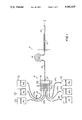
FIG. 1 is schematic view of a system in accordance with the invention illustrating the main components thereof;
FIG. 2 is a perspective view of an irrigation system in accordance with the invention;
FIG. 3 is a fragmentary perspective view of irrigating solution reservoir storage means, showing three irrigating solution reservoirs stored in place with three additional reservoirs yet to be stored;
FIG. 4 is an exploded fragmentary view of a control unit and handpiece means in a system in accordance with the invention, showing liquid solution coupling and selector means for fluidly coupling the handpiece means to a selected one of the liquid solutions in a respective solution reservoir, and pump means for causing the selected one of the liquid solutions to flow from its reservoir to the handpiece means;
FIGS. 5A-5C are exploded plan, rear and front views respectively of selector valve means for use in the invention;
FIG. 6 is an enlarged elevation view of pump means for use in the invention;
FIG. 7 is a fragmentary section view of means for heating the selected one of the liquid solutions as it flows to the handpiece means;
FIG. 8 is a detail view of handpiece means and an associated applicator tip or cannula for use in the invention;
FIG. 9 is a schematic view of electrical circuitry for use in the invention;
FIG. 10 is a fragmentary perspective view illustrating the connection of tubing to a solution reservoir; and
FIGS. 11A-11C are perspective views of possible arrangements of the reservoir storage means in accordance with the invention showing its flexibility in set-up.
Referring now to the drawings wherein like reference characters designate identical or corresponding parts throughout the several views, and more particularly to FIG. 1, an irrigation system in accordance with the invention, generally designated 10, comprises a plurality of solution reservoirs 12 (six shown), each reservoir including a quantity of a respective liquid solution substantially sealed within a container, handpiece means 14 for delivering a selected one of the liquid solutions contained in one of the reservoirs 12 directly to a treatment site, liquid solution coupling and selector means, generally designated 16, for coupling handpiece means 14 to a selected one of the liquid solutions in a respective solution reservoir 12, and pump means 18 for causing a selected one of the liquid solutions to flow from its reservoir 12 thereof to the handpiece means 14 for delivery to the treatment site. Heating means for heating the selected solution as it flows to the handpiece are designated 19.
The liquid solution coupling and selector means 16 include selector valve means 20 having a plurality of inputs 22, an output 24, and means for coupling a selected one of the inputs 22 to the output 24, first tubing means 28 for fluidly coupling each of the solutions in a respective reservoir 12 to a respective one of the inputs 22 of the selector valve inputs 22, and second tubing means 30 for fluidly coupling the output 24 of the selector valve means to the handpiece means 14.
Referring to FIG. 2 illustrating an embodiment of the apparatus schematically illustrated in FIG. 1, six solution reservoirs 121 -126 are stored in wall-mounted reservoir storage means 32. A control unit enclosure 35 houses the pump and selector valve means. First tubing means 28 couple each of the solution reservoirs 121 -126 to the selector valve inputs within enclosure 35. Second tubing means 30 couples the handpiece means 14 to the output of the pump means within enclosure 35. The handpiece 14 is mounted on the side of the housing 35 for easy access. The power to operate the pump means and heater is obtained through a line cord 33 upon the depression of a conventional foot switch 37.
A solution reservoir 12 forming a part of the system of the invention comprises a closed container 36 in which a quantity of a particular irrigation solution 341, 342 and . . . 346 is substantially sealed. Referring to FIG. 3, the container 36 in the illustrated embodiment comprises a 1000 ml., self-collapsing, non-vented, molded container made of low density polyethelene which itself is housed within an outer cardboard carton 44. Containers of this type are available from the Hedwin Company of Baltimore, Md. under the name "Cubitainer." Each container has a neck having an opening over which a polyethelene cap 38 having a penetratable membrane, also available from Hedwin Company, is screw fastened.
According to one feature of the invention, each of the liquid solutions 341, 342 . . . 346 has a color which is distinguishable from the color of the other liquid solutions, such as through the use of a coloring agent. It is understood that one of the solutions may have a clear "color", which will distinguish it from the other solutions. At the same time, visually apparent, color-coded indicia are associated with each of the solution reservoirs and the second tubing means 30 is formed at least in part of transparent material so that the color of the solution flowing through the tubing during the treatment is visible. In this manner, the identity of the solution being used can be quickly and easily verified by reference to the color-coded indicia associated with the solution reservoirs.
For example, referring to FIGS. 1 and 2, in the illustrated embodiment the solution 341 comprises an aqueous bacteriostatic rinse solution for use as a flush and which has been colored orange, solution 342 comprises a 1% zinc chloride irrigating solution which has been given a dark green color, solution 343 comprises a 2% sodium fluoride irrigating solution which has been given a blue color, solution 344 comprises a 1.64% stannous fluoride gel having a clear "color", solution 345 comprises a 0.12% chlorhexidine gluconate irrigating solution given a cherry red color, and solution 346 comprises a 1.7% hydrogen peroxide solution having a pink color.
Each of the outer cartons 44 of containers 36 is provided with color-coded indicia corresponding to the color of the solution in the container which it houses. For example, the front panel of carton 44 of the reservoir 121 containing orange aqueous bacteriostatic rinsing solution is colored orange, the front panel of the carton 44 of the reservoir 122 containing green zinc chloride solution is colored green, etc. Thus, color-coded indicia are associated with each of the solution reservoirs which correspond to the liquid solution contained therein.
In order to refer to the color-coded indicia associated with the reservoirs as described above, the solution reservoirs must be mounted such that the color-coded indicia associated therewith are visible during the treatment procedure. For example, as seen in FIG. 2, the solution reservoirs 121 -126 are mounted on a wall by means of the reservoir storage means 32 so that the front panels of the outer cartons are easily seen during treatment.
By these features, it is possible for the practitioner to simply and reliably verify that the desired liquid solution is being administered as the irrigation process is taking place. The practitioner need merely observe the color of the liquid solution as it flows through the transparent second tubing means 30 and glance at the color-coded indicia provided on the reservoir 12 of the desired solution to assure correspondence between them. For example, if the practitioner is treating a patient with a solution believed to be zinc chloride solution 342 and wishes to verify this fact, he need only note the color (green) of the liquid flowing through transparent second tubing means 30 and glance at the reservoirs to ascertain which has corresponding color indicia. It is a simple matter to ascertain that the corresponding reservoir 122 indeed contains zinc chloride solution.
It will of course, be understood that color-coded indicia may be associated in some other manner with the solution reservoirs. For example, fluid level windows 46 may be formed through the front panel of each of the cartons 44 through which the liquid solution is visible in its respective container 36. The color of the liquid solution itself may be viewed through the window so that the solution itself comprises the color-coded indicia associated with the respective reservoirs.
The liquid solutions are preferably flavor coordinated, i.e., are provided with substantially the same predetermined flavor. For example, a peppermint flavor may be imparted to each of the irrigating solutions by suitable flavoring agents. By this feature, a patient may be treated with two or more solutions during the same procedure, one after the other, without being subjected to the discomfort which would normally occur when a person tastes two or more diverse flavors, one immediately after the other.
Referring to FIG. 3, according to another feature of the invention, the reservoir storage means 32 has a modular construction and, in the illustrated embodiment, comprises an assembly of two single-shelf storage racks 48 and 50 situated one over the other, and which are fastened to each other by means of machine screws 51. Storage means 32 are illustrated with solution reservoirs 124 -126 in their stored positions in the upper rack 50, coupled to the first tubing means, and prior to the storage of the reservoirs 121 -123 in the lower rack 48.
Each modular storage rack 48-50 comprises a metal shelf 52 having a retainer bar 54 fastened to its front edge, a pair of side panels 56 extending upwardly from its side edges, and a rear panel 58 extending upwardly from the rear edge of the shelf. The shelf 52 is long enough to accommodate three liquid solution reservoirs 12 in side-by-side fashion, so that an assembly of two storage racks 48 and 50 as illustrated in FIGS. 2 and 3 will accommodate six liquid solution reservoirs. As will be clear from FIGS. 2 and 3, the construction of the reservoir storage means 32 is such that when mounted on a wall as in FIG. 2, or on other supports described below, the color-coded indicia associated with the reservoirs are visible during the procedure.
As seen in FIG. 3, for purposes discussed below, the reservoir storage means 32 has a respective identifying indicia 59 associated with each of the reservoir positions, as by printing a respective one of the numberal "1" to "6" on the retainer bar 54 directly in front of the respective reservoir position. For example, solution reservoir 126 is positioned on rack 50 directly at the position designated by the indicia "6." Three slots 60 are formed through each of the shelves 52, each slot extending beneath a respective reservoir position. A metal shroud 62 is fastened onto the outer surface of at least one of the side panels 56 of each of the racks 48 and 50.
The first tubing means 28 which fluidly couple the six reservoirs to the selector valve, comprise six 150 inch o.d. tubes 42 which are enclosed within an outer sheath 64 over the major portion of their lengths. The exposed upstream end portions of tubes 42 not surrounded by sheath 64 are routed to the side of the reservoir storage means 32 and into the space defined between side panels 56 and shrouds 62. Tubes 421, 422 and 423 are passed through an opening 66 in the side panel 56 of the lower shelf storage rack, and through respective slots 60 in lower shelf 52. Tubes 424, 425 and 426 are passed through a corresponding opening 66 in the side panel 56 of the upper shelf storage rack 50, and then through respective slots 60 in upper shelf 52. A quick-disconnect right angle membrane-penetrating adaptor 40 is connected to the end of each of the tubes 42 for quick-disconnect connection to the membrane cap 38 of a respective reservoir to pierce the membrane, thereby coupling each tube to the solution contained in that reservoir.
Each of the tubes 42 are preferably color-coded substantially over its entire length. For example, in the illustrated embodiment, the tube 421, which connects solution 341 in the reservoir 121, situated at position 1 in storage means 32 to an input 221 of selector valve means 20, is formed of red polyethelene. The tube 422, which connects solution 342 in the reservoir 122 situated in position 2 of storage means 32 to an input 222 of selector valve means 20, is formed of yellow polyethelene, etc.
Referring now to FIGS. 4 and 5, the exposed downstream end portions of the tubes 421 -426 of first tubing means 28 are connected to respective inputs 221 -226 of the selector valve means 20 which are provided with respective indicia 68 (FIG. 5B) corresponding to indicia 59 on the storage means 32. For example, tube 421 has its upstream end connected to reservoir 121 situated at the position associated with the indicia "1" of storage means 32 while its downstream end is connected to the input 221 of the selector valve means associated with the indicia "1". That the ends of the same tube are connected on the one hand to the reservoir 121 at the position designated by the indicia "1", and on the other hand to the selector valve input 221 designated by indicia "1", is ensured by color coding the tube 421 as described above. Thus, it is a simple matter to determine that the same tube, i.e. the "red" tube 421, has one of its ends connected to the reservoir 121 situated at the position designated by indicia "1" in the storage means 32, and its other end connected to the input 221, designated "1", of the selector valve means. This feature practically eliminates the possibility of connecting an end of a tube already connected at its other end to a particular solution reservoir, to an incorrect input of the selector valve.
Referring to FIG. 5, selector valve means 20 comprises a main body 70 having a central cylinder core or stem 72 rotatably mounted therein. Six liquid inlet passages 74 are formed through the body 70, each inlet passage opening into a respective input port 22 at its outer end, and at its inner end, into the bore which receives the rotatable core 72 in a plane common with the inner ends of the other inlet passages 74. A liquid outlet passage 76 is formed in the rotatable core 72 having one end opening into the selector valve output port 24 and another end opening onto the cylindrical core surface in the plane of the inner ends of passages 74. The selector valve means also comprises a selector knob 78 which is fastened to the end region of core 72 which protrudes through a face plate 80 of selector valve 20.
Referring now to FIG. 4 which comprises an exploded perspective view of the control unit enclosure 35 and the components housed therein, enclosure 35 comprises a bottom member 38, a U-shaped top and side member 88, and front and rear panels 92 and 94. The bottom and top members 86 and 88 are affixed to each other by screws 90 with the edges of the front and rear panels captured in front and rear (not shown) channels 98 to form the enclosure.
The sheath 64 of first tubing means 28 passes through an opening 96 in rear panel 94 and the downstream end portions of tubes 421, 422 . . . 426 are connected to respective valve inputs 221, 222, . . . 226 of selector valve means 20 using the color coding of the tubes to ensure accurate connections. The protruding part of the rotatable core 72 of valve means 20 passes through an opening 100 in the front panel 92 and selector knob 78 is affixed thereto. Indicia 82 are provided on the outer surface of the front panel 92 which correspond in position to the indicia 68 on the rear surface of the body 70 of the selector valve means 20. The selector knob 78 is rotated so that an arrow 79 (FIG. 5C) on knob 78 points to a particular one of the indicia 82 on front panel 92. The core 78 is thus rotated until the end of the outlet passage 76 communicates with the particular inlet passage 74 corresponding to the inlet coupled to the desired irrigating solution. For example, when the knob is rotated so that the pointer 78 indicates the indicia designated "6", the outlet passage 76 communicates with the inlet passage 74 which opens into the inlet port 226 which is coupled to the solution 346 contained in the reservoir 126.
Also situated within the control unit enclosure 35 are the pump means, generally designated 18 in FIG. 1. In accordance with the invention, the pump means 18 comprises a peristaltic pump assembly 102. Referring to FIG. 6, the peristaltic pump assembly 102 comprises a pump housing 104 to which a rotor 106 is rotatably mounted by a shaft 108. A roller 110 is journalled to each end of rotor 106. A substantially circular channel 112 is formed through housing 104 which is bounded on its inner periphery by a deformable collar 114. A length of silicone pump tubing 116 is situated within channel 112 and terminates at its inlet end in a barbed inlet fitting 118, and at its outlet end in a barbed outlet fitting 120. The shaft 108 is connected to a 115 volt electric motor 122 (FIG. 4) adapted to rotate at 30 rpm.
A length of tubing 124, comprising a part of the second tubing means 30, has one end connected to the outlet port 24 of the selector valve means 20 and its other end connected to the inlet fitting 118 of peristaltic pump 102 so that the silicone pump tubing 116 comprises a part of the second tubing means 30.
Still referring to FIG. 4, the control unit enclosure 35 also houses a transformer 128 and a relay 130. The line cord 33 and conductors 132 leading to the footswitch 37 extend through openings in the rear panel 94. A power light 134, an irrigating light 136 and a power switch 138 are installed on the front panel 92. As noted above, the selector knob 78 is also mounted over the front panel 92. The enclosure 35 also houses the electric circuitry associated with these components shown in FIG. 9 and described below.
Referring now to FIG. 8, the handpiece means 14 comprises a Delrin plastic handpiece core 152 to which a female quick-disconnect fitting 154 is threadly fastened adapted to be connected to the male fitting 141. A silicone sheath 156 is positioned over the handpiece core 152 to improve gripping of the handpiece means. A conventional Luer lock adaptor 158 is connected to the front of the handpiece core. A disposable side-port cannula 160 is connected to the handpiece means by the Luer lock adaptor.
Certain aspects of the invention described above provide advantages in the installation of the system. Thus, one of the problems with conventional apparatus of the type illustrated in the above-mentioned U.S. Pat. No. 4,215,476 is in making space available for the structure associated with the plurality of solution reservoirs. By providing the reservoir storage means 32 in the form of modular single-shelf racks, a high degree of flexibility is provided. For example, in addition to being hung on a wall as illustrated in FIG. 2, the reservoir storage means 32 can be placed on a countertop 168 (FIG. 11A), or on a mobile cart 170 (FIG. 11B) or in a cabinet 172 underneath a counter (FIG. 11C).
If the reservoir storage means 32 comprises more than one single shelf storage rack module, the rack modules are initially assembled to each other to form the reservoir storage means. After positioning the storage means where desired, the first or umbilical tubing means 28 are then attached to the solution storage rack assembly by routing the same from the control unit enclosure 35 to the side of the storage rack and through the space defined by the shroud 62 as described above. Appropriate straps or clamps may be used to fix the tubing in position. The tubing 42 is passed through the openings 66 in the side panels 56 of the shelf storage racks and a membrane-piercing quick-disconnect adaptor 40 is then attached to the end of each of the tubings 42.
The solution reservoirs are preferably provided in the packaged form shown in FIG. 10. In particular, referring to FIG. 10, each reservoir 12 is preferably provided with a color-coded solution sealed within a collapsible, non-vented plastic container by a membrane cap 38. The solution-filled container is pre-packaged in a carton 44 having a front panel provided with color-coded indicia corresponding to the solution in the container. A liquid level slot 46 is formed in the front panel. The top 45 of carton 44 is perforated at 47 to facilitate separating the top from the carton prior to use.
A solution reservoir 121 to be situated in the position designated "1" on a solution storage rack is chosen and the membrane-piercing quick disconnect adaptor 40 is located which is connected to the tubing 421. The adaptor 40 is then connected to the membrane cap 38 of the container 36 whereupon the reservoir is inverted and placed in position "1" on the rack with the color-coded front panel and solution level slot facing outwardly. This process is repeated with the remaining reservoirs.
Referring to FIG. 9, in the standard operation of the system, the power switch 138 on the front panel of the control unit enclosure 35 is closed to its "on" position. As is apparent from FIG. 9, with the power switch 138 closed, and foot switch 37 open, the peristaltic pump motor 122 is not activated so that solution is not flowing through the system. A relay-operated switch 162 is in its solid-line position so that a low voltage of about 10 volts is applied by the transformer 128 across a heater circuit 160. With the relay switch 162 in the illustrated position, a power dissipating resistor 164 is placed in series with the resistance heating wire 140 in heater circuit 160. A low level current flows through the heating wire 140 which is adapted to maintain the temperature of the static flush solution within the handpiece tubing means 145 in a range of between about 96°-100° F.
The solution selector knob 78 is then turned to a position designated by indicia 82 corresponding to the solution storage rack position, designated by indicia 59 on the reservoir storage means 32 in which the reservoir containing the desired irrigating solution is stored. The footswitch 37 is closed thereby activating the peristaltic pump motor 122, the irrigating light 136, and relay 130. The desired irrigating solution is pumped from its reservoir through the first and second tubing means to the handpiece. The solution in the clear handpiece tubing means 145 will change color as the chosen solution replaces the flush solution initially present in the tubing. Activation of relay 130 causes the relay switch 162 to move to the position designated 162a whereby the power dissipating resistor 164 is removed from the heating circuit 160, whereupon a higher voltage of about 20 volts is applied by the transformer 128 across the heating circuit 160 which now only includes the resistance heating wire 140. The larger current flowing through the resistance heating wire enables the temperature of the liquid solution flowing through the tubing to be heated to the same temperature as that to which the static liquid solution was maintained prior to activation of the footswitch 37.
When treatment with the particular irrigating solution is completed, the system can be either switched to another solution, or the selector knob may be turned to select the flush solution. It takes approximately 8 to 15 seconds for the new solution to replace the old solution in the handpiece tubing. The apparatus enables the handpiece tubing and handpiece to be flushed with the flush solution prior to shutting off the unit.
The use of a peristaltic pump enables the irrigating solution to be delivered in pulsed jets at a desired substantially constant pressure and at a substantially constant volumetric flow rate. For example, the system is preferably designed to deliver approximately 22 to 25 ml. per minute of irrigating solution at a pressure of about 25 psi. The heating means described above will heat the irrigating solution from room temperature to a temperature in the range of between about 96 to 102 degrees under both constant and intermittant operation. The color-coded irrigation solutions are delivered all the way from the conveniently pre-packaged reservoirs to the side-port cannulas through a continuous path of FDA-approved material. The peristaltic pump does not invade the delivery path so as to avoid contamination and also serves as a natural check valve since it cannot aspirate solution back into the cannula after being deactivated. The heating device is also indirect and non-invasive to the solution path. The handpiece is removeable for autoclaving.
Obviously, numerous modifications and variations of the present invention are possible in the light of the above teachings. It is therefore to be understood that within the scope of the claims appended hereto, the invention may be practiced otherwise than as specifically disclosed herein.
Claims (15)
1. Periodontal irrigating system for delivering one of a plurality of liquid irrigating solutions to a treatment site in an oral cavity, comprising:
a plurality of solution reservoirs, each reservoir including a quantity of a respective liquid irrigating solution substantially sealed within a container, each of said liquid irrigating solutions having a color which is distinguishable from the color of the other liquid irrigating solutions, and wherein color coded indicia are associated with each of said solution reservoirs corresponding to said liquid irrigating solution thereof;
handpiece means for delivering a selected one of said liquid solutions directly to a treatment site;
liquid solution coupling and selector means for fluidly coupling said handpiece means and a selected one of said liquid solutions of a respective solution reservoir, said liquid solution coupling and selector means including selector valve means having a plurality of inputs, an output, and means for coupling a selected one of said inputs and said output, first tubing means for fluidly coupling each of said liquid irrigating solutions and a respective one of said inputs of said selector valve means, and second tubing means for fluidly coupling said output of said selector valve means and said handpiece means;
said second tubing means including a flexible tube means having a length proximate to said handpiece means, and formed of substantially clear transparent material such that the color of a liquid irrigating solution following through said flexible tube means is visible during treatment with said handpiece means at said oral cavity; and pump means for causing a selected one of said liquid solutions to flow from said reservoir thereof to said handpiece means for delivery to the treatment site.
2. A system as recited in claim 1 wherein said pump means operatively engage said second tubing means and being situated entirely out of the path of said flow of said selected liquid solution from said reservoir thereof to said handpiece means.
3. A system as recited in claim 1 further including reservoir mounting means comprising storage means having first indicia means for designating respective solution reservoirs stored therein, and wherein said selector valve means have second indicia means associated with said coupling means thereof corresponding to said first indicia means for designating respective solution reservoirs.
4. A system as recited in claim 1 wherein each of said solution reservoirs further includes a carton in which said container is housed, and wherein said color coded indicia is applied to said carton.
5. A system as recited in claim 5 wherein said color coded indicia comprises a color which is substantially the same as the color of said liquid solution.
6. A system as recited in claim 5 wherein said color coded indicia is applied to a region of said carton and wherein said reservoirs are mounted with said regions to which said color coded indicia is applied being visible.
7. A system as recited in claim 1 wherein said color-coded indicia comprises said solution contained in said container.
8. A system as recited in claim 1 further including means for mounting said solutions reservoirs such that said color-coded indicia are visible during treatment.
9. A system as recited in claim 1 wherein said liquid solutions have substantially the same flavor.
10. Irrigation system for delivering one of a plurality of liquid solutions to a treatment site, comprising:
a plurality of solution reservoirs, each reservoir including a quantity of a respective liquid solution substantially sealed within a container, each of said liquid solutions having a color which is distinguishable from the color of the other liquid solutions, and wherein color coded indicia are associated with each of said solution reservoirs corresponding to said liquid solution thereof;
handpiece means for delivering a selected one of said liquid solutions directly to a treatment site;
liquid solution coupling and selector means for fluidly coupling said handpiece means and a selected one of said liquid solutions of a respective solution reservoir, said liquid solution coupling and selector means including selector valve mans having a plurality of inputs, and output, and for coupling a selected one of said inputs and said output, first tubing means for fluidly coupling each of said liquid solutions and a respective one of said inputs of said selector valve means, and second tubing means for fluidly coupling said output of said selector valve means and said handpiece means;
said second tubing means including a flexible tube means formed of substantially clear transparent material such that the color of a liquid solution flowing through said tube means is visible during treatment;
pump means for causing a selected one of said liquid solutions to flow from said reservoir thereof to said handpiece means for delivery to the treatment site; and
means for heating a selected one of said liquid solutions as it flows from said reservoir thereof to said handpiece for delivery to said treatment site, said heating means being situated entirely out of the flow of said selected one of said liquid solutions.
11. Irrigation system for delivering one of a plurality of liquid solutions to a treatment site, comprising:
a plurality of solution reservoirs, each reservoir including a quantity of a respective liquid solution substantially sealed within a container;
handpiece means for delivering a selected one of said liquid solutions directly to a treatment site;
liquid solution coupling and selector means for fluidly coupling said handpiece means and a selected one of said liquid solutions of a respective solution reservoir, said liquid solution coupling and selector means including selector valve means having a plurality of inputs, and output, and means for coupling a selected one of said inputs and said output, first tubing means for fluidly coupling each of said liquid solutions and a respective one of said inputs of said selector valve means, and second tubing means for fluidly coupling said output of said selector valve means and said handpiece means;
pump means for causing a selected one of said liquid solutions to flow from said reservoir thereof to said handpiece means for delivery to the treatment site;
means for heating a selected one of said liquid solutions as it flows from said reservoir thereof to said handpiece for delivery to said treatment site, said heating means being situated entirely out of the flow of said selected one of said liquid solutions; and wherein
said second tubing means includes a handpiece tubing portion comprising a transparent handpiece tube coupling an output side of said pump means to said handpiece means, said heating means comprise a heating element affixed to an outer surface of said handpiece tube, and said second tubing means further includes a transparent outer tube substantially encasing said handpiece tube and said heating element.
12. Irrigation system for delivering one of a plurality of liquid solutions to a treatment site, comprising:
a plurality of solution reservoirs, each reservoir including a quantity of a respective liquid solution substantially sealed within a container;
reservoir storage means for storing said solution reservoirs, said storage means having first indicia means for designating respective solution reservoirs stored therein;
handpiece means for delivering a selected one of said liquid solutions directly to a treatment site;
liquid solution coupling and selector means for fluidly coupling said handpiece means and a selected one of said liquid solutions of a respective solution reservoir, said liquid solution coupling and selector means including selector valve means having a plurality of inputs, and output, and means for coupling a selected one of said inputs and said output, first tubing means for fluidly coupling each of said liquid solutions and a respective one of said inputs of said selector valve means, and second tubing means for fluidly coupling said output of said selector valve means and said handpiece means;
said selector valve means having second indicia means associated with said coupling means thereof, said second indicia means corresponding to said first indicia means for designating respective solution reservoirs;
means for causing a selected one of said liquid solutions to flow from said reservoir thereof to said handpiece means for delivery to the treatment site; and wherein said reservoir storage means comprise at least one shelf on which said solution reservoirs are mounted, said first indicia means being associated with said shelf.
13. A system as recited in claim 12 where said coupling means of said selector valve means includes a selector knob, said second indicia means being associated with said selector knob.
14. Irrigation system for delivering liquid solution to a treatment site, comprising:
at least one solution reservoir, each including a quantity of a respective liquid solution;
handpiece means for delivering a liquid solution from each of said at least one liquid solution reservoirs directly to a treatment site;
tubing means for fluidly coupling said handpiece means to said liquid solution in said liquid reservoir;
means for causing said liquid solution to flow from said reservoir thereof to said handpiece means for delivery to the treatment; and
means for heating said liquid solution as it flows to said handpiece means, said heating means including a resistance wire affixed to a length of said tubing means proximate to said handpiece means over a length thereof and out of the path of liquid solution flowing therethrough, said resistance wire forming a part of electric heater circuit means;
wherein said electric heater circuit means further includes a secondary winding of a transformer, said system further including operating circuit means including a primary winding of said transformer and power switch means for selectively energizing said transformer windings;
wherein said flow causing means comprises a pump driven by an electric motor and wherein said operating circuit means further includes operating conductor means parallely coupled to said primary winding, said pump motor and an operating switch means coupled to said operating conductor means so that said pump motor is energized upon closing said power and operating switch means; and
wherein said secondary transformer winding of said heater circuit means is a variably tapped winding, and further including a relay coupled to said operating conductor means which is energized upon closing said power and operating switch means, and means for changing the tapped winding of said secondary transformer upon energizing said relay to increase the voltage applied across said resistance wire.
15. An irrigation system as recited in claim 14 wherein said heater circuit means further includes a power dissipating resistor, and wherein said system further comprises means for removing said power dissipating resistor from said heater circuit means upon energizing said relay.
Priority Applications (7)
| Application Number | Priority Date | Filing Date | Title |
|---|---|---|---|
| US07/519,405 US5060825A (en) | 1990-05-04 | 1990-05-04 | Irrigation system and method for delivering a selected one of multiple liquid solutions to a treatment site |
| EP19910909915 EP0531366A4 (en) | 1990-05-04 | 1991-05-03 | Irrigation system and method for delivering a selected one of multiple liquid solutions to a treatment site |
| CA002082063A CA2082063A1 (en) | 1990-05-04 | 1991-05-03 | Irrigation system and method for delivering a selected one of multiple liquid solution to a treatment site |
| AU78793/91A AU7879391A (en) | 1990-05-04 | 1991-05-03 | Irrigation system and method for delivering a selected one of multiple liquid solutions to a treatment site |
| PCT/US1991/003048 WO1991017112A1 (en) | 1990-05-04 | 1991-05-03 | Irrigation system and method for delivering a selected one of multiple liquid solutions to a treatment site |
| JP91509838A JPH05507014A (en) | 1990-05-04 | 1991-05-03 | Irrigation device and method for delivering a predetermined one of a plurality of solutions to a treatment area |
| US07/763,540 US5199604A (en) | 1990-05-04 | 1991-09-23 | Irrigation system and method for delivering a selected one of multiple liquid solutions to a treatment site |
Applications Claiming Priority (1)
| Application Number | Priority Date | Filing Date | Title |
|---|---|---|---|
| US07/519,405 US5060825A (en) | 1990-05-04 | 1990-05-04 | Irrigation system and method for delivering a selected one of multiple liquid solutions to a treatment site |
Related Child Applications (1)
| Application Number | Title | Priority Date | Filing Date |
|---|---|---|---|
| US07/763,540 Continuation US5199604A (en) | 1990-05-04 | 1991-09-23 | Irrigation system and method for delivering a selected one of multiple liquid solutions to a treatment site |
Publications (1)
| Publication Number | Publication Date |
|---|---|
| US5060825A true US5060825A (en) | 1991-10-29 |
Family
ID=24068190
Family Applications (1)
| Application Number | Title | Priority Date | Filing Date |
|---|---|---|---|
| US07/519,405 Expired - Fee Related US5060825A (en) | 1990-05-04 | 1990-05-04 | Irrigation system and method for delivering a selected one of multiple liquid solutions to a treatment site |
Country Status (6)
| Country | Link |
|---|---|
| US (1) | US5060825A (en) |
| EP (1) | EP0531366A4 (en) |
| JP (1) | JPH05507014A (en) |
| AU (1) | AU7879391A (en) |
| CA (1) | CA2082063A1 (en) |
| WO (1) | WO1991017112A1 (en) |
Cited By (92)
| Publication number | Priority date | Publication date | Assignee | Title |
|---|---|---|---|---|
| US5255820A (en) * | 1991-04-24 | 1993-10-26 | Ecolab Inc. | Apparatus for dilution of liquid products |
| US5344074A (en) * | 1991-09-25 | 1994-09-06 | Ecolab Inc. | Dispensing apparatus having a removable variable proportioning and metering device |
| US5443094A (en) * | 1993-06-10 | 1995-08-22 | Ecolab Inc. | Concentrated product dilution system |
| US5749526A (en) * | 1995-08-28 | 1998-05-12 | Gary R. Laabs | Centrally installed cleaning/washing system for buildings |
| US5906810A (en) * | 1987-03-17 | 1999-05-25 | Turner; Robert E. | Formulations and uses thereof in the prevention and treatment of oral lesions |
| US6030212A (en) * | 1996-09-27 | 2000-02-29 | Dentsply Research & Development Corp. | Stacking reservoir and scaler system |
| WO2001039684A1 (en) * | 1999-12-03 | 2001-06-07 | Conair Corporation | Liquid container |
| US20030000965A1 (en) * | 2001-06-29 | 2003-01-02 | Bach David T. | Precision fluid dispensing system |
| WO2003035537A2 (en) * | 2001-10-22 | 2003-05-01 | Trek Bicycle Corporation | Dual bladder sports hydration system |
| US6793387B1 (en) * | 1999-05-08 | 2004-09-21 | Chata Biosystems, Inc. | Apparatus for automatic preparation of a mixture and method |
| US20040195382A1 (en) * | 2001-02-12 | 2004-10-07 | Garth Anderson | Device for dispensing liquid |
| US20050006410A1 (en) * | 2001-06-29 | 2005-01-13 | David Bach | Precision fluid dispensing system |
| US20050194407A1 (en) * | 2001-06-29 | 2005-09-08 | Bach David T. | Precision fluid dispensing system |
| US20070202459A1 (en) * | 2006-02-27 | 2007-08-30 | Water Pik, Inc. | Tip for oral irrigator |
| US20080008979A1 (en) * | 2006-07-07 | 2008-01-10 | Water Pik, Inc. | Oral irrigator |
| US20080146991A1 (en) * | 2006-12-18 | 2008-06-19 | Chris Hernandez | Hand operated dispenser for surgical irrigation fluids |
| WO2009060456A2 (en) * | 2007-11-11 | 2009-05-14 | Avraham Eliyahou | Gingival massaging device |
| US20090156562A1 (en) * | 2005-11-14 | 2009-06-18 | Winch Peter D | Novel colored solutions of injectable drugs and their pharmaceutically acceptable salts |
| US20090208900A1 (en) * | 2008-02-20 | 2009-08-20 | Leon Emmanuel Jew | Bifunctional dental apparatus |
| US20090240196A1 (en) * | 2008-03-20 | 2009-09-24 | Beutlich Lp, Pharmaceuticals | Device and method for drug delivery |
| US20100233645A1 (en) * | 1997-12-05 | 2010-09-16 | Biolase Technology, Inc. | Efficient laser and fluid conditioning and cutting system |
| USD629884S1 (en) | 2009-12-16 | 2010-12-28 | Water Pik, Inc. | Powered irrigator for sinus cavity rinse |
| US8113832B2 (en) | 2002-12-31 | 2012-02-14 | Water Pik, Inc. | Hand held oral irrigator |
| USD670373S1 (en) | 2010-12-16 | 2012-11-06 | Water Pik, Inc. | Powered irrigator for sinus cavity rinse |
| US8408483B2 (en) | 2006-02-24 | 2013-04-02 | Water Pik, Inc. | Adjustable flow regulator for dental water jet |
| US20140127641A1 (en) * | 2012-11-02 | 2014-05-08 | Braun Gmbh | Oral Irrigator |
| USD707350S1 (en) | 2012-10-11 | 2014-06-17 | Water Pik, Inc. | Handheld water flosser |
| US8801667B2 (en) | 2009-12-16 | 2014-08-12 | Water Pik, Inc. | Pump for powered irrigator for sinus cavity rinse |
| USD714929S1 (en) | 2013-03-14 | 2014-10-07 | Water Pik, Inc. | Base for water flosser |
| USD714930S1 (en) | 2013-03-14 | 2014-10-07 | Water Pik, Inc. | Reservoir for water flosser |
| USD717427S1 (en) | 2013-03-14 | 2014-11-11 | Water Pik, Inc. | Handle for water flosser |
| USD725770S1 (en) | 2013-03-14 | 2015-03-31 | Water Pik, Inc. | Reservoir for water flosser |
| USD756122S1 (en) | 2009-01-28 | 2016-05-17 | Water Pik, Inc. | Oral irrigator tip |
| US20160161773A1 (en) * | 2014-12-05 | 2016-06-09 | Beijing Boe Display Technology Co., Ltd. | Liquid crystal pump and method for ejecting liquid crystal using the same |
| US9468892B2 (en) | 2014-02-07 | 2016-10-18 | Hydra-Flex, Inc. | Modular chemical dispensing assembly |
| USD772397S1 (en) | 2014-12-01 | 2016-11-22 | Water Pik, Inc. | Oral irrigator with a charging device |
| USD772396S1 (en) | 2014-12-01 | 2016-11-22 | Water Pik, Inc. | Handheld oral irrigator |
| USD780908S1 (en) | 2015-11-03 | 2017-03-07 | Water Pik, Inc. | Handheld oral irrigator |
| USD782657S1 (en) | 2016-03-02 | 2017-03-28 | Water Pik, Inc. | Oral irrigator handle |
| USD782656S1 (en) | 2016-01-25 | 2017-03-28 | Water Pik, Inc. | Oral irrigator |
| USD783810S1 (en) | 2016-02-22 | 2017-04-11 | Water Pik, Inc. | Handle for an oral irrigator |
| USD783809S1 (en) | 2016-01-25 | 2017-04-11 | Water Pik, Inc. | Oral irrigator handle |
| USD786422S1 (en) | 2016-01-25 | 2017-05-09 | Water Pik, Inc. | Oral irrigator |
| USD788907S1 (en) | 2013-03-14 | 2017-06-06 | Water Pik, Inc. | Water flosser base unit with reservoir lid |
| USD794773S1 (en) | 2016-07-19 | 2017-08-15 | Water Pik, Inc. | Oral irrigator |
| USD796028S1 (en) | 2016-07-19 | 2017-08-29 | Water Pik, Inc. | Oral irrigator |
| USD802119S1 (en) | 2016-03-02 | 2017-11-07 | Water Pik, Inc. | Oral irrigator |
| USD802120S1 (en) | 2007-02-27 | 2017-11-07 | Water Pik, Inc. | Tip for oral irrigator |
| USD802747S1 (en) | 2016-07-19 | 2017-11-14 | Water Pik, Inc. | Reservoir for oral irrigator |
| USD804016S1 (en) | 2016-02-05 | 2017-11-28 | Water Pik, Inc. | Handheld oral irrigator |
| USD804018S1 (en) | 2016-07-19 | 2017-11-28 | Water Pik, Inc. | Base for an oral irrigator |
| USD807822S1 (en) | 2016-07-19 | 2018-01-16 | Water Pik, Inc. | Power supply cartridge |
| USD809650S1 (en) | 2016-02-22 | 2018-02-06 | Water Pik, Inc. | Oral irrigator |
| USD809651S1 (en) | 2016-07-19 | 2018-02-06 | Water Pik, Inc. | Combination base and reservoir for an oral irrigator |
| US9980793B2 (en) | 2013-11-27 | 2018-05-29 | Water Pik, Inc. | Oral hygiene system |
| USD819956S1 (en) | 2016-01-25 | 2018-06-12 | Water Pik, Inc. | Kit bag |
| USD822196S1 (en) | 2016-01-14 | 2018-07-03 | Water Pik, Inc. | Oral irrigator |
| USD822825S1 (en) | 2016-12-15 | 2018-07-10 | Water Pik, Inc. | Oral irrigator unit |
| US10016254B2 (en) | 2013-12-20 | 2018-07-10 | Water Pik, Inc. | Dental water jet |
| USD822826S1 (en) | 2016-12-15 | 2018-07-10 | Water Pik, Inc. | Oral irrigator base |
| US10022207B2 (en) | 2013-11-27 | 2018-07-17 | Water Pik, Inc. | Oral irrigator with slide pause switch |
| USD825741S1 (en) | 2016-12-15 | 2018-08-14 | Water Pik, Inc. | Oral irrigator handle |
| US20180250467A1 (en) * | 2015-04-30 | 2018-09-06 | Steven Gill Anaesthetic Services Ltd | Injectables |
| USD829886S1 (en) | 2016-12-15 | 2018-10-02 | Water Pik, Inc. | Oral irrigator base |
| USD829887S1 (en) | 2017-02-06 | 2018-10-02 | Water Pik, Inc. | Oral irrigator reservoir |
| US10105201B2 (en) | 2012-10-11 | 2018-10-23 | Water Pik, Inc. | Interdental cleaner using water supply |
| USD832420S1 (en) | 2016-12-15 | 2018-10-30 | Water Pik, Inc. | Oral irrigator base |
| USD832419S1 (en) | 2016-12-15 | 2018-10-30 | Water Pik, Inc. | Oral irrigator unit |
| USD832418S1 (en) | 2016-12-15 | 2018-10-30 | Water Pik, Inc. | Oral irrigator base |
| USD833000S1 (en) | 2016-12-15 | 2018-11-06 | Water Pik, Inc. | Oral irrigator unit |
| USD833602S1 (en) | 2017-02-06 | 2018-11-13 | Water Pik, Inc. | Oral irrigator base |
| USD833601S1 (en) | 2017-02-06 | 2018-11-13 | Water Pik, Inc. | Oral irrigator |
| USD833600S1 (en) | 2016-12-15 | 2018-11-13 | Water Pik, Inc. | Oral irrigator reservoir |
| USD834180S1 (en) | 2016-12-15 | 2018-11-20 | Water Pik, Inc. | Oral irrigator base |
| USD839409S1 (en) | 2016-12-15 | 2019-01-29 | Water Pik, Inc. | Oral irrigator unit |
| USD840023S1 (en) | 2016-12-15 | 2019-02-05 | Water Pik, Inc. | Oral irrigator reservoir |
| USD840022S1 (en) | 2016-12-15 | 2019-02-05 | Water Pik, Inc. | Oral irrigator handle |
| US10258442B2 (en) | 2009-03-20 | 2019-04-16 | Water Pik, Inc. | Oral irrigator appliance with radiant energy delivery for bactericidal effect |
| USD867579S1 (en) | 2016-12-15 | 2019-11-19 | Water Pik, Inc. | Oral irrigator unit |
| USD868243S1 (en) | 2018-03-16 | 2019-11-26 | Water Pik, Inc. | Oral irrigator tip |
| USD877324S1 (en) | 2018-05-17 | 2020-03-03 | Water Pik, Inc. | Oral irrigator handle |
| USD888936S1 (en) | 2019-02-22 | 2020-06-30 | Water Pik, Inc. | Cordless water flosser |
| USD889636S1 (en) | 2019-02-22 | 2020-07-07 | Water Pik, Inc. | Water flosser |
| US10779922B2 (en) | 2016-12-15 | 2020-09-22 | Water Pik, Inc. | Pause valve and swivel assemblies for oral irrigator handle |
| US10835356B2 (en) | 2016-01-25 | 2020-11-17 | Water Pik, Inc. | Swivel assembly for oral irrigator handle |
| US10993867B2 (en) | 2016-03-02 | 2021-05-04 | Water Pik, Inc. | Actuation assembly for an oral irrigator |
| US11213376B2 (en) | 2016-01-25 | 2022-01-04 | Water Pik, Inc. | Reduced form factor oral irrigator |
| CN114452023A (en) * | 2021-02-24 | 2022-05-10 | 北京大学口腔医学院 | Intelligent cleaner for oral cavity |
| US11389279B2 (en) | 2016-12-15 | 2022-07-19 | Water Pik, Inc. | Oral irrigator with magnetic attachment |
| USD966498S1 (en) | 2020-09-15 | 2022-10-11 | Water Pik, Inc. | Oral irrigator |
| US11826214B2 (en) | 2014-12-01 | 2023-11-28 | Water Pik, Inc. | Oral irrigator |
| USD1016274S1 (en) | 2021-02-16 | 2024-02-27 | Water Pik, Inc. | Oral irrigator |
Families Citing this family (6)
| Publication number | Priority date | Publication date | Assignee | Title |
|---|---|---|---|---|
| DE4319630A1 (en) * | 1993-06-15 | 1994-12-22 | Storz Endoskop Gmbh | Instrument that can be inserted into the human body |
| BE1007758A4 (en) * | 1993-11-17 | 1995-10-17 | Cedetec Sa | Injection device for a solution in the body of a body. |
| GB9622594D0 (en) * | 1996-10-30 | 1997-01-08 | Bridge House Lab Ltd | Improvements relating to cleansing apparatus and methods |
| EP2742899B1 (en) * | 2004-10-14 | 2022-08-10 | DENTSPLY SIRONA Inc. | Air polishing prophylaxis system |
| US7713237B2 (en) * | 2005-09-28 | 2010-05-11 | Alcon, Inc. | Surgical cassette for intraocular pressure control |
| CN103637852A (en) * | 2013-11-16 | 2014-03-19 | 苏州华恒医用器械有限公司 | Medical water gas control device |
Citations (14)
| Publication number | Priority date | Publication date | Assignee | Title |
|---|---|---|---|---|
| US2425277A (en) * | 1945-08-13 | 1947-08-05 | Davis John Berry | Trocar |
| US3614389A (en) * | 1969-01-21 | 1971-10-19 | Imre Malisza | Electrically heated dental wax supplying and manipulating tools |
| US3756471A (en) * | 1971-08-19 | 1973-09-04 | Eastman Kodak Co | Dispenser container having a tear-out sight gauge |
| US3921858A (en) * | 1973-11-05 | 1975-11-25 | Robert A Bemm | Automatic confection decorating system |
| US4215476A (en) * | 1977-03-25 | 1980-08-05 | Armstrong Alexander S | Health services combination irrigator and aspirator |
| US4344571A (en) * | 1979-04-26 | 1982-08-17 | Kuendig Armin | Self-contained device for spraying a heated spray material |
| US4356937A (en) * | 1980-11-17 | 1982-11-02 | Pepsico. Inc. | Syrup distribution system |
| US4366920A (en) * | 1977-12-28 | 1983-01-04 | Greenfield Jr Irving E | Demand preparation soluble coffee urn |
| US4513885A (en) * | 1979-05-04 | 1985-04-30 | Cole-Parmer Instrument Company | Dispenser having a flexible fluid container and a rotor compressible fluid discharge tube |
| US4527713A (en) * | 1984-06-13 | 1985-07-09 | Car Fresh Manufacturing Company, Inc. | Coin operated fragrance dispenser |
| US4592728A (en) * | 1981-12-07 | 1986-06-03 | Davis Dennis R | Periodontal lavage delivery system |
| US4667084A (en) * | 1984-04-30 | 1987-05-19 | Meltex Verbindungs-Technik Gmbh | Electrically heated hose for heating melted adhesive and atomizing air fed to a spraying head |
| US4708266A (en) * | 1986-03-21 | 1987-11-24 | The Coca-Cola Company | Concentrate dispensing system for a post-mix beverage dispenser |
| US4886452A (en) * | 1987-10-14 | 1989-12-12 | Kaltenbach & Voigt Gmbh & Co. | Dental spray handpiece |
Family Cites Families (3)
| Publication number | Priority date | Publication date | Assignee | Title |
|---|---|---|---|---|
| US3718973A (en) * | 1970-05-01 | 1973-03-06 | R Slater | Dental system |
| US3924335A (en) * | 1971-02-26 | 1975-12-09 | Ultrasonic Systems | Ultrasonic dental and other instrument means and methods |
| CA1335417C (en) * | 1988-01-06 | 1995-05-02 | George E. Warrin | Apparatus for scaling teeth and lavage |
-
1990
- 1990-05-04 US US07/519,405 patent/US5060825A/en not_active Expired - Fee Related
-
1991
- 1991-05-03 JP JP91509838A patent/JPH05507014A/en active Pending
- 1991-05-03 WO PCT/US1991/003048 patent/WO1991017112A1/en not_active Application Discontinuation
- 1991-05-03 AU AU78793/91A patent/AU7879391A/en not_active Abandoned
- 1991-05-03 CA CA002082063A patent/CA2082063A1/en not_active Abandoned
- 1991-05-03 EP EP19910909915 patent/EP0531366A4/en not_active Withdrawn
Patent Citations (14)
| Publication number | Priority date | Publication date | Assignee | Title |
|---|---|---|---|---|
| US2425277A (en) * | 1945-08-13 | 1947-08-05 | Davis John Berry | Trocar |
| US3614389A (en) * | 1969-01-21 | 1971-10-19 | Imre Malisza | Electrically heated dental wax supplying and manipulating tools |
| US3756471A (en) * | 1971-08-19 | 1973-09-04 | Eastman Kodak Co | Dispenser container having a tear-out sight gauge |
| US3921858A (en) * | 1973-11-05 | 1975-11-25 | Robert A Bemm | Automatic confection decorating system |
| US4215476A (en) * | 1977-03-25 | 1980-08-05 | Armstrong Alexander S | Health services combination irrigator and aspirator |
| US4366920A (en) * | 1977-12-28 | 1983-01-04 | Greenfield Jr Irving E | Demand preparation soluble coffee urn |
| US4344571A (en) * | 1979-04-26 | 1982-08-17 | Kuendig Armin | Self-contained device for spraying a heated spray material |
| US4513885A (en) * | 1979-05-04 | 1985-04-30 | Cole-Parmer Instrument Company | Dispenser having a flexible fluid container and a rotor compressible fluid discharge tube |
| US4356937A (en) * | 1980-11-17 | 1982-11-02 | Pepsico. Inc. | Syrup distribution system |
| US4592728A (en) * | 1981-12-07 | 1986-06-03 | Davis Dennis R | Periodontal lavage delivery system |
| US4667084A (en) * | 1984-04-30 | 1987-05-19 | Meltex Verbindungs-Technik Gmbh | Electrically heated hose for heating melted adhesive and atomizing air fed to a spraying head |
| US4527713A (en) * | 1984-06-13 | 1985-07-09 | Car Fresh Manufacturing Company, Inc. | Coin operated fragrance dispenser |
| US4708266A (en) * | 1986-03-21 | 1987-11-24 | The Coca-Cola Company | Concentrate dispensing system for a post-mix beverage dispenser |
| US4886452A (en) * | 1987-10-14 | 1989-12-12 | Kaltenbach & Voigt Gmbh & Co. | Dental spray handpiece |
Cited By (153)
| Publication number | Priority date | Publication date | Assignee | Title |
|---|---|---|---|---|
| US5906810A (en) * | 1987-03-17 | 1999-05-25 | Turner; Robert E. | Formulations and uses thereof in the prevention and treatment of oral lesions |
| US5255820A (en) * | 1991-04-24 | 1993-10-26 | Ecolab Inc. | Apparatus for dilution of liquid products |
| US5344074A (en) * | 1991-09-25 | 1994-09-06 | Ecolab Inc. | Dispensing apparatus having a removable variable proportioning and metering device |
| US5443094A (en) * | 1993-06-10 | 1995-08-22 | Ecolab Inc. | Concentrated product dilution system |
| US5749526A (en) * | 1995-08-28 | 1998-05-12 | Gary R. Laabs | Centrally installed cleaning/washing system for buildings |
| US5868320A (en) * | 1995-08-28 | 1999-02-09 | Laabs; Gary R. | Centrally installed cleaning/washing system for buildings |
| US6030212A (en) * | 1996-09-27 | 2000-02-29 | Dentsply Research & Development Corp. | Stacking reservoir and scaler system |
| US6293793B1 (en) | 1996-09-27 | 2001-09-25 | Dentsply Research & Development Corp. | Stackable reservoir and scaler system |
| US20100233645A1 (en) * | 1997-12-05 | 2010-09-16 | Biolase Technology, Inc. | Efficient laser and fluid conditioning and cutting system |
| US6793387B1 (en) * | 1999-05-08 | 2004-09-21 | Chata Biosystems, Inc. | Apparatus for automatic preparation of a mixture and method |
| US6419486B1 (en) | 1999-12-03 | 2002-07-16 | Gimelli Produktions Ag | Fluid reservoir |
| WO2001039684A1 (en) * | 1999-12-03 | 2001-06-07 | Conair Corporation | Liquid container |
| US20040195382A1 (en) * | 2001-02-12 | 2004-10-07 | Garth Anderson | Device for dispensing liquid |
| US7320437B2 (en) * | 2001-02-26 | 2008-01-22 | Instrument Supplies Limited | Device for dispensing liquid |
| US20030000965A1 (en) * | 2001-06-29 | 2003-01-02 | Bach David T. | Precision fluid dispensing system |
| US6739478B2 (en) * | 2001-06-29 | 2004-05-25 | Scientific Products & Systems Llc | Precision fluid dispensing system |
| US20050006410A1 (en) * | 2001-06-29 | 2005-01-13 | David Bach | Precision fluid dispensing system |
| US20050194407A1 (en) * | 2001-06-29 | 2005-09-08 | Bach David T. | Precision fluid dispensing system |
| WO2003035537A2 (en) * | 2001-10-22 | 2003-05-01 | Trek Bicycle Corporation | Dual bladder sports hydration system |
| WO2003035537A3 (en) * | 2001-10-22 | 2003-10-02 | Randall B Bailey | Dual bladder sports hydration system |
| US9980794B2 (en) | 2002-12-31 | 2018-05-29 | Water Pik, Inc. | Irrigating device with variable pressure pulse |
| US10617500B2 (en) | 2002-12-31 | 2020-04-14 | Water Pik, Inc. | Oral irrigator |
| US8113832B2 (en) | 2002-12-31 | 2012-02-14 | Water Pik, Inc. | Hand held oral irrigator |
| US20090156562A1 (en) * | 2005-11-14 | 2009-06-18 | Winch Peter D | Novel colored solutions of injectable drugs and their pharmaceutically acceptable salts |
| US8641649B2 (en) | 2006-02-24 | 2014-02-04 | Water Pik, Inc. | Pump for dental water jet |
| US8408483B2 (en) | 2006-02-24 | 2013-04-02 | Water Pik, Inc. | Adjustable flow regulator for dental water jet |
| US10010389B2 (en) | 2006-02-24 | 2018-07-03 | Water Pik, Inc. | Dental water jet device |
| US11197745B2 (en) | 2006-02-24 | 2021-12-14 | Water Pik, Inc. | Removable fluid connection fitting for oral irrigator |
| US9050157B2 (en) | 2006-02-24 | 2015-06-09 | Water Pik, Inc. | Dental water jet with storage container reservoir cover |
| US11872097B2 (en) | 2006-02-24 | 2024-01-16 | Water Pik, Inc. | Dental water jet with storage container reservoir cover |
| US8888727B2 (en) | 2006-02-24 | 2014-11-18 | Water Pik, Inc. | Vibration damping for dental water jet |
| US8808209B2 (en) | 2006-02-24 | 2014-08-19 | Water Pik, Inc. | Dental water jet irrigator handle |
| US11432916B2 (en) | 2006-02-24 | 2022-09-06 | Water Pik, Inc. | Oral irrigator with handle support |
| US20070202459A1 (en) * | 2006-02-27 | 2007-08-30 | Water Pik, Inc. | Tip for oral irrigator |
| US9775692B2 (en) | 2006-07-07 | 2017-10-03 | Water Pik, Inc. | Oral irrigator with variable pressure |
| US8403665B2 (en) | 2006-07-07 | 2013-03-26 | Water Pik, Inc. | Oral irrigator |
| US20080008979A1 (en) * | 2006-07-07 | 2008-01-10 | Water Pik, Inc. | Oral irrigator |
| USD747464S1 (en) | 2006-07-07 | 2016-01-12 | Water Pik, Inc. | Handheld oral irrigator |
| US7670141B2 (en) * | 2006-07-07 | 2010-03-02 | Water Pik, Inc. | Oral irrigator |
| US20080146991A1 (en) * | 2006-12-18 | 2008-06-19 | Chris Hernandez | Hand operated dispenser for surgical irrigation fluids |
| USD867580S1 (en) | 2007-02-27 | 2019-11-19 | Water Pik, Inc. | Oral irrigator tip with bristles |
| USD802120S1 (en) | 2007-02-27 | 2017-11-07 | Water Pik, Inc. | Tip for oral irrigator |
| WO2009060456A2 (en) * | 2007-11-11 | 2009-05-14 | Avraham Eliyahou | Gingival massaging device |
| US20100311007A1 (en) * | 2007-11-11 | 2010-12-09 | Avraham Eliyahov | Gingival massaging device |
| WO2009060456A3 (en) * | 2007-11-11 | 2010-03-11 | Avraham Eliyahou | Gingival massaging device |
| US20090208900A1 (en) * | 2008-02-20 | 2009-08-20 | Leon Emmanuel Jew | Bifunctional dental apparatus |
| US20090240196A1 (en) * | 2008-03-20 | 2009-09-24 | Beutlich Lp, Pharmaceuticals | Device and method for drug delivery |
| US7749191B2 (en) | 2008-03-20 | 2010-07-06 | Beutlich Lp, Pharmaceuticals | Device and method for drug delivery |
| USD756122S1 (en) | 2009-01-28 | 2016-05-17 | Water Pik, Inc. | Oral irrigator tip |
| US10258442B2 (en) | 2009-03-20 | 2019-04-16 | Water Pik, Inc. | Oral irrigator appliance with radiant energy delivery for bactericidal effect |
| US11173020B2 (en) | 2009-03-20 | 2021-11-16 | Water Pik, Inc. | Oral irrigator appliance with radiant energy delivery for bactericidal effect |
| US9061096B2 (en) | 2009-12-16 | 2015-06-23 | Water Pik, Inc. | Powered irrigator for sinus cavity rinse |
| USD629884S1 (en) | 2009-12-16 | 2010-12-28 | Water Pik, Inc. | Powered irrigator for sinus cavity rinse |
| US8808245B2 (en) | 2009-12-16 | 2014-08-19 | Water Pik, Inc. | Powered irrigator for sinus cavity rinse with detachable reservoir |
| US8801667B2 (en) | 2009-12-16 | 2014-08-12 | Water Pik, Inc. | Pump for powered irrigator for sinus cavity rinse |
| USD694398S1 (en) | 2010-12-16 | 2013-11-26 | Water Pik, Inc. | Powered irrigator for sinus cavity rinse |
| USD670373S1 (en) | 2010-12-16 | 2012-11-06 | Water Pik, Inc. | Powered irrigator for sinus cavity rinse |
| US10105201B2 (en) | 2012-10-11 | 2018-10-23 | Water Pik, Inc. | Interdental cleaner using water supply |
| USD707350S1 (en) | 2012-10-11 | 2014-06-17 | Water Pik, Inc. | Handheld water flosser |
| US20140127641A1 (en) * | 2012-11-02 | 2014-05-08 | Braun Gmbh | Oral Irrigator |
| US10945912B2 (en) | 2013-03-14 | 2021-03-16 | Water Pik, Inc. | Oral irrigator with variable output fluid characteristics |
| US9597161B2 (en) | 2013-03-14 | 2017-03-21 | Water Pik, Inc. | Oral irrigator with integrated lid and base |
| USD754330S1 (en) | 2013-03-14 | 2016-04-19 | Water Pik, Inc. | Handle for a water flosser |
| USD731640S1 (en) | 2013-03-14 | 2015-06-09 | Water Pik, Inc. | Reservoir for a water flosser |
| USD725770S1 (en) | 2013-03-14 | 2015-03-31 | Water Pik, Inc. | Reservoir for water flosser |
| USD714929S1 (en) | 2013-03-14 | 2014-10-07 | Water Pik, Inc. | Base for water flosser |
| USD740936S1 (en) | 2013-03-14 | 2015-10-13 | Water Pik, Inc. | Water flosser base unit |
| US9642677B2 (en) | 2013-03-14 | 2017-05-09 | Water Pik, Inc. | Oral irrigator with massage mode |
| USD788907S1 (en) | 2013-03-14 | 2017-06-06 | Water Pik, Inc. | Water flosser base unit with reservoir lid |
| USD718855S1 (en) | 2013-03-14 | 2014-12-02 | Water Pik, Inc. | Base for water flosser |
| USD714930S1 (en) | 2013-03-14 | 2014-10-07 | Water Pik, Inc. | Reservoir for water flosser |
| USD798440S1 (en) | 2013-03-14 | 2017-09-26 | Water Pik, Inc. | Water flosser base unit |
| USD717427S1 (en) | 2013-03-14 | 2014-11-11 | Water Pik, Inc. | Handle for water flosser |
| US11039906B2 (en) | 2013-11-27 | 2021-06-22 | Water Pik, Inc. | Tip ejection assembly for an oral irrigator |
| US10022207B2 (en) | 2013-11-27 | 2018-07-17 | Water Pik, Inc. | Oral irrigator with slide pause switch |
| US9980793B2 (en) | 2013-11-27 | 2018-05-29 | Water Pik, Inc. | Oral hygiene system |
| US10016254B2 (en) | 2013-12-20 | 2018-07-10 | Water Pik, Inc. | Dental water jet |
| US9468892B2 (en) | 2014-02-07 | 2016-10-18 | Hydra-Flex, Inc. | Modular chemical dispensing assembly |
| USD819196S1 (en) | 2014-12-01 | 2018-05-29 | Water Pik, Inc. | Handheld oral irrigator |
| US11826214B2 (en) | 2014-12-01 | 2023-11-28 | Water Pik, Inc. | Oral irrigator |
| USD772397S1 (en) | 2014-12-01 | 2016-11-22 | Water Pik, Inc. | Oral irrigator with a charging device |
| USD772396S1 (en) | 2014-12-01 | 2016-11-22 | Water Pik, Inc. | Handheld oral irrigator |
| US10288050B2 (en) * | 2014-12-05 | 2019-05-14 | Boe Technology Group Co., Ltd. | Liquid crystal pump and method for ejecting liquid crystal using the same |
| US20160161773A1 (en) * | 2014-12-05 | 2016-06-09 | Beijing Boe Display Technology Co., Ltd. | Liquid crystal pump and method for ejecting liquid crystal using the same |
| US20180250467A1 (en) * | 2015-04-30 | 2018-09-06 | Steven Gill Anaesthetic Services Ltd | Injectables |
| USD780908S1 (en) | 2015-11-03 | 2017-03-07 | Water Pik, Inc. | Handheld oral irrigator |
| USD873025S1 (en) | 2016-01-14 | 2020-01-21 | Water Pik, Inc. | Toothbrush handle |
| USD822196S1 (en) | 2016-01-14 | 2018-07-03 | Water Pik, Inc. | Oral irrigator |
| USD907763S1 (en) | 2016-01-14 | 2021-01-12 | Water Pik, Inc. | Oral irrigator |
| USD880688S1 (en) | 2016-01-14 | 2020-04-07 | Water Pik, Inc. | Oral irrigator handle |
| USD786422S1 (en) | 2016-01-25 | 2017-05-09 | Water Pik, Inc. | Oral irrigator |
| US10835356B2 (en) | 2016-01-25 | 2020-11-17 | Water Pik, Inc. | Swivel assembly for oral irrigator handle |
| USD819956S1 (en) | 2016-01-25 | 2018-06-12 | Water Pik, Inc. | Kit bag |
| USD782656S1 (en) | 2016-01-25 | 2017-03-28 | Water Pik, Inc. | Oral irrigator |
| US11213376B2 (en) | 2016-01-25 | 2022-01-04 | Water Pik, Inc. | Reduced form factor oral irrigator |
| USD783809S1 (en) | 2016-01-25 | 2017-04-11 | Water Pik, Inc. | Oral irrigator handle |
| US11642203B2 (en) | 2016-01-25 | 2023-05-09 | Water Pik, Inc. | Oral irrigator handle with hose connector fittings |
| USD815274S1 (en) | 2016-02-05 | 2018-04-10 | Water Pik, Inc. | Handheld oral irrigator |
| USD804016S1 (en) | 2016-02-05 | 2017-11-28 | Water Pik, Inc. | Handheld oral irrigator |
| USD873409S1 (en) | 2016-02-22 | 2020-01-21 | Water Pik, Inc. | Oral irrigator |
| USD783810S1 (en) | 2016-02-22 | 2017-04-11 | Water Pik, Inc. | Handle for an oral irrigator |
| USD809650S1 (en) | 2016-02-22 | 2018-02-06 | Water Pik, Inc. | Oral irrigator |
| USD839410S1 (en) | 2016-02-22 | 2019-01-29 | Water Pik, Inc. | Oral irrigator |
| USD802119S1 (en) | 2016-03-02 | 2017-11-07 | Water Pik, Inc. | Oral irrigator |
| US11607359B2 (en) | 2016-03-02 | 2023-03-21 | Water Pik, Inc. | Actuation assembly for an oral irrigator |
| US10993867B2 (en) | 2016-03-02 | 2021-05-04 | Water Pik, Inc. | Actuation assembly for an oral irrigator |
| USD782657S1 (en) | 2016-03-02 | 2017-03-28 | Water Pik, Inc. | Oral irrigator handle |
| USD802747S1 (en) | 2016-07-19 | 2017-11-14 | Water Pik, Inc. | Reservoir for oral irrigator |
| USD809651S1 (en) | 2016-07-19 | 2018-02-06 | Water Pik, Inc. | Combination base and reservoir for an oral irrigator |
| USD794773S1 (en) | 2016-07-19 | 2017-08-15 | Water Pik, Inc. | Oral irrigator |
| USD796028S1 (en) | 2016-07-19 | 2017-08-29 | Water Pik, Inc. | Oral irrigator |
| USD804018S1 (en) | 2016-07-19 | 2017-11-28 | Water Pik, Inc. | Base for an oral irrigator |
| USD807822S1 (en) | 2016-07-19 | 2018-01-16 | Water Pik, Inc. | Power supply cartridge |
| US11389279B2 (en) | 2016-12-15 | 2022-07-19 | Water Pik, Inc. | Oral irrigator with magnetic attachment |
| USD870268S1 (en) | 2016-12-15 | 2019-12-17 | Water Pik, Inc. | Oral irrigator handle |
| USD872855S1 (en) | 2016-12-15 | 2020-01-14 | Water Pik, Inc. | Oral irrigator unit |
| USD833600S1 (en) | 2016-12-15 | 2018-11-13 | Water Pik, Inc. | Oral irrigator reservoir |
| USD840023S1 (en) | 2016-12-15 | 2019-02-05 | Water Pik, Inc. | Oral irrigator reservoir |
| USD839409S1 (en) | 2016-12-15 | 2019-01-29 | Water Pik, Inc. | Oral irrigator unit |
| USD867579S1 (en) | 2016-12-15 | 2019-11-19 | Water Pik, Inc. | Oral irrigator unit |
| USD833000S1 (en) | 2016-12-15 | 2018-11-06 | Water Pik, Inc. | Oral irrigator unit |
| USD834180S1 (en) | 2016-12-15 | 2018-11-20 | Water Pik, Inc. | Oral irrigator base |
| USD840022S1 (en) | 2016-12-15 | 2019-02-05 | Water Pik, Inc. | Oral irrigator handle |
| USD822825S1 (en) | 2016-12-15 | 2018-07-10 | Water Pik, Inc. | Oral irrigator unit |
| USD893017S1 (en) | 2016-12-15 | 2020-08-11 | Water Pik, Inc. | Oral irrigator unit |
| US10779922B2 (en) | 2016-12-15 | 2020-09-22 | Water Pik, Inc. | Pause valve and swivel assemblies for oral irrigator handle |
| USD822826S1 (en) | 2016-12-15 | 2018-07-10 | Water Pik, Inc. | Oral irrigator base |
| USD832418S1 (en) | 2016-12-15 | 2018-10-30 | Water Pik, Inc. | Oral irrigator base |
| USD832419S1 (en) | 2016-12-15 | 2018-10-30 | Water Pik, Inc. | Oral irrigator unit |
| USD825741S1 (en) | 2016-12-15 | 2018-08-14 | Water Pik, Inc. | Oral irrigator handle |
| USD832420S1 (en) | 2016-12-15 | 2018-10-30 | Water Pik, Inc. | Oral irrigator base |
| USD829886S1 (en) | 2016-12-15 | 2018-10-02 | Water Pik, Inc. | Oral irrigator base |
| USD829887S1 (en) | 2017-02-06 | 2018-10-02 | Water Pik, Inc. | Oral irrigator reservoir |
| USD833601S1 (en) | 2017-02-06 | 2018-11-13 | Water Pik, Inc. | Oral irrigator |
| USD833602S1 (en) | 2017-02-06 | 2018-11-13 | Water Pik, Inc. | Oral irrigator base |
| USD868243S1 (en) | 2018-03-16 | 2019-11-26 | Water Pik, Inc. | Oral irrigator tip |
| USD890917S1 (en) | 2018-03-16 | 2020-07-21 | Water Pik, Inc. | Oral irrigator tip |
| USD950710S1 (en) | 2018-05-17 | 2022-05-03 | Water Pik, Inc. | Oral irrigator handle |
| USD975843S1 (en) | 2018-05-17 | 2023-01-17 | Water Pik, Inc. | Oral irrigator handle |
| USD877324S1 (en) | 2018-05-17 | 2020-03-03 | Water Pik, Inc. | Oral irrigator handle |
| USD969994S1 (en) | 2019-02-22 | 2022-11-15 | Water Pik, Inc. | Cordless water flosser |
| USD889636S1 (en) | 2019-02-22 | 2020-07-07 | Water Pik, Inc. | Water flosser |
| USD945601S1 (en) | 2019-02-22 | 2022-03-08 | Water Pik, Inc. | Cordless water flosser |
| USD913486S1 (en) | 2019-02-22 | 2021-03-16 | Water Pik, Inc. | Cordless water flosser |
| USD956957S1 (en) | 2019-02-22 | 2022-07-05 | Water Pik, Inc. | Reservoir for water flosser |
| USD980414S1 (en) | 2019-02-22 | 2023-03-07 | Water Pik, Inc. | Reservoir for water flosser |
| USD888936S1 (en) | 2019-02-22 | 2020-06-30 | Water Pik, Inc. | Cordless water flosser |
| USD902385S1 (en) | 2019-02-22 | 2020-11-17 | Water Pik, Inc. | Cordless water flosser |
| USD992728S1 (en) | 2019-02-22 | 2023-07-18 | Water Pik, Inc. | Base for water flosser |
| USD912241S1 (en) | 2019-02-22 | 2021-03-02 | Water Pik, Inc. | Water flosser |
| USD966498S1 (en) | 2020-09-15 | 2022-10-11 | Water Pik, Inc. | Oral irrigator |
| USD1016274S1 (en) | 2021-02-16 | 2024-02-27 | Water Pik, Inc. | Oral irrigator |
| CN114452023A (en) * | 2021-02-24 | 2022-05-10 | 北京大学口腔医学院 | Intelligent cleaner for oral cavity |
Also Published As
| Publication number | Publication date |
|---|---|
| EP0531366A4 (en) | 1993-09-01 |
| CA2082063A1 (en) | 1991-11-05 |
| EP0531366A1 (en) | 1993-03-17 |
| WO1991017112A1 (en) | 1991-11-14 |
| AU7879391A (en) | 1991-11-27 |
| JPH05507014A (en) | 1993-10-14 |
Similar Documents
| Publication | Publication Date | Title |
|---|---|---|
| US5060825A (en) | Irrigation system and method for delivering a selected one of multiple liquid solutions to a treatment site | |
| US5199604A (en) | Irrigation system and method for delivering a selected one of multiple liquid solutions to a treatment site | |
| US3912168A (en) | Irrigation lavage | |
| US6390815B1 (en) | Multiple solution dental irrigator | |
| US4215476A (en) | Health services combination irrigator and aspirator | |
| US4193197A (en) | Fluid supply unit and systems for dental and medical instruments | |
| US8506293B2 (en) | Ultrasonic endodontic dental irrigator | |
| US20160361135A1 (en) | Programmable dental device | |
| US4862876A (en) | Dental and throat cleaning system | |
| EP0121085B1 (en) | Apparatus for the preparation of medical infusion solutions | |
| US4247288A (en) | Method and apparatus for root canal irrigation | |
| US4696669A (en) | Hand held combination flush with adjustable nozzle and/or suction apparatus | |
| US5458563A (en) | Toothbrushes | |
| US5573398A (en) | Dental hygiene device and cleaning solution | |
| US5061268A (en) | Disposable electrosurgical pencil with in-line filter and method | |
| WO1985001879A1 (en) | Peritoneal dialysis apparatus | |
| EP0125784A1 (en) | Ultrasonic endodontic dental apparatus | |
| US20080014545A1 (en) | Apical irrigation fluid delivery apparatus | |
| JPH084626B2 (en) | Self-contained liquid dosing device | |
| ES2299843T3 (en) | CHLORINE DIOXIDE PRODUCTION. | |
| US5123839A (en) | Air and water heater for dental instruments | |
| US4193196A (en) | Fluid supply unit for dental instruments | |
| US5697132A (en) | System and method for automated mixing and delivery of embalming fluid to a cadaver | |
| EP0322223A2 (en) | Apparatus for mixing the components of a liquid body treatment composition | |
| EP1468967A2 (en) | An apparatus for sterilising and sanitising water circuits |
Legal Events
| Date | Code | Title | Description |
|---|---|---|---|
| AS | Assignment |
Owner name: SULTAN CHEMISTS, INC., NEW JERSEY Free format text: ASSIGNMENT OF ASSIGNORS INTEREST.;ASSIGNORS:PALMER, LEE;MARSALL, JAMES;REEL/FRAME:005297/0995;SIGNING DATES FROM 19900409 TO 19900410 |
|
| REMI | Maintenance fee reminder mailed | ||
| LAPS | Lapse for failure to pay maintenance fees | ||
| FP | Lapsed due to failure to pay maintenance fee |
Effective date: 19951101 |
|
| STCH | Information on status: patent discontinuation |
Free format text: PATENT EXPIRED DUE TO NONPAYMENT OF MAINTENANCE FEES UNDER 37 CFR 1.362 |