US5056570A - Capless vehicle refueling system - Google Patents
Capless vehicle refueling system Download PDFInfo
- Publication number
- US5056570A US5056570A US07/498,612 US49861290A US5056570A US 5056570 A US5056570 A US 5056570A US 49861290 A US49861290 A US 49861290A US 5056570 A US5056570 A US 5056570A
- Authority
- US
- United States
- Prior art keywords
- fuel
- valve
- chamber
- fill
- passageway
- Prior art date
- Legal status (The legal status is an assumption and is not a legal conclusion. Google has not performed a legal analysis and makes no representation as to the accuracy of the status listed.)
- Expired - Lifetime
Links
Images


Classifications
-
- B—PERFORMING OPERATIONS; TRANSPORTING
- B60—VEHICLES IN GENERAL
- B60K—ARRANGEMENT OR MOUNTING OF PROPULSION UNITS OR OF TRANSMISSIONS IN VEHICLES; ARRANGEMENT OR MOUNTING OF PLURAL DIVERSE PRIME-MOVERS IN VEHICLES; AUXILIARY DRIVES FOR VEHICLES; INSTRUMENTATION OR DASHBOARDS FOR VEHICLES; ARRANGEMENTS IN CONNECTION WITH COOLING, AIR INTAKE, GAS EXHAUST OR FUEL SUPPLY OF PROPULSION UNITS IN VEHICLES
- B60K15/00—Arrangement in connection with fuel supply of combustion engines or other fuel consuming energy converters, e.g. fuel cells; Mounting or construction of fuel tanks
- B60K15/03—Fuel tanks
- B60K15/035—Fuel tanks characterised by venting means
- B60K15/03519—Valve arrangements in the vent line
-
- B—PERFORMING OPERATIONS; TRANSPORTING
- B60—VEHICLES IN GENERAL
- B60K—ARRANGEMENT OR MOUNTING OF PROPULSION UNITS OR OF TRANSMISSIONS IN VEHICLES; ARRANGEMENT OR MOUNTING OF PLURAL DIVERSE PRIME-MOVERS IN VEHICLES; AUXILIARY DRIVES FOR VEHICLES; INSTRUMENTATION OR DASHBOARDS FOR VEHICLES; ARRANGEMENTS IN CONNECTION WITH COOLING, AIR INTAKE, GAS EXHAUST OR FUEL SUPPLY OF PROPULSION UNITS IN VEHICLES
- B60K15/00—Arrangement in connection with fuel supply of combustion engines or other fuel consuming energy converters, e.g. fuel cells; Mounting or construction of fuel tanks
- B60K15/03—Fuel tanks
- B60K15/04—Tank inlets
- B60K15/0406—Filler caps for fuel tanks
- B60K2015/0419—Self-sealing closure caps, e.g. that don't have to be removed manually
- B60K2015/0429—Self-sealing closure caps, e.g. that don't have to be removed manually actuated by the nozzle
-
- B—PERFORMING OPERATIONS; TRANSPORTING
- B60—VEHICLES IN GENERAL
- B60K—ARRANGEMENT OR MOUNTING OF PROPULSION UNITS OR OF TRANSMISSIONS IN VEHICLES; ARRANGEMENT OR MOUNTING OF PLURAL DIVERSE PRIME-MOVERS IN VEHICLES; AUXILIARY DRIVES FOR VEHICLES; INSTRUMENTATION OR DASHBOARDS FOR VEHICLES; ARRANGEMENTS IN CONNECTION WITH COOLING, AIR INTAKE, GAS EXHAUST OR FUEL SUPPLY OF PROPULSION UNITS IN VEHICLES
- B60K15/00—Arrangement in connection with fuel supply of combustion engines or other fuel consuming energy converters, e.g. fuel cells; Mounting or construction of fuel tanks
- B60K15/03—Fuel tanks
- B60K15/04—Tank inlets
- B60K2015/0458—Details of the tank inlet
- B60K2015/048—Arrangements for sealing the fuel inlet during filling
Definitions
- the present invention relates to an assembly for controlling filling of the vehicle fuel tank having a filler neck. More particularly, the present invention relates to a fuel and fuel vapor handling system which controls a filling operation of a fuel tank and which controls the discharge of fuel vapors from the tank and the filler neck both during and after the filling operation.
- a fuel cap with a sealing gasket typically is used to close the open end of a fuel tank filler neck. Once the fuel tank is filled and the fuel-dispensing nozzle is withdrawn from the filler neck, the fuel cap is reattached to the filler neck so that the sealing gasket forms a seal between the fuel cap and the filler neck. Thus, the fuel cap closes the open end of the filler neck to block discharge of liquid fuel and fuel vapor from the fuel tank through the filler neck. It is known however to place pressure relief and vacuum relief valves in fuel caps to permit some controlled venting of fuel vapors in the filler neck while the fuel cap is mounted on the filler neck.
- a filler neck configured to "open” automatically to receive a fuel-dispensing pump nozzle therein during refueling and "close” automatically once the attendant withdraws the pump nozzle from the filler neck without requiring the attendant to reattach a fuel cap to the filler neck would be an improvement over many conventional capped filler-neck systems.
- a capless filler neck could make vehicle refueling more convenient for the consumer because no action other than inserting a pump nozzle into the open end of the filler neck would be required to refuel a vehicle.
- a capless filler-neck system would be configured in accordance with the present invention to include internal liquid fuel and fuel vapor control means.
- One object of the present invention is to provide a refueling system which does not require use of a conventional fuel cap.
- Another object of the present invention is to provide a capless refueling system which is capable of maintaining acceptable fuel tank fill rates without premature shutoff of the fuel nozzle.
- Yet another object of the present invention is to provide a refueling system which controls handling fuel vapor in the system both during and after the fuel refilling process.
- Still another object of the present invention is to provide a system for automatically venting the fuel tank during refueling in response to insertion of a fuel-dispensing pump nozzle into a fuel tank filler neck.
- the fuel tank is vented to the atmosphere, while in another embodiment of the invention, the fuel tank is vented to a canister for processing fuel vapor in an onboard, fuel-vapor recovery system.
- Another object of the present invention is to provide an internal drain system for discharging water or other contaminants that might inadvertently leak into the filler neck from the filler neck to the ground underneath the vehicle to minimize the opportunity for such contaminants to be carried into the fuel tank through the filler neck during refueling.
- Yet another object of the invention is to provide a nozzle shutoff system for controlling the pressure in the region of the filler neck containing the pump nozzle during refueling to control triggering shutoff of fuel flow from a pressure-actuated pump nozzle once the fuel tank is filled to a predetermined maximum volume to control filling of the fuel tank in such a way as to prevent overfilling of the fuel tank.
- Still another object of the invention is to provide a pressure and vacuum relief system in a fuel tank filler neck which will enable the fuel tank to vent whenever a predetermined high pressure or a predetermined negative pressure exists within the fuel tank even when the filler neck is otherwise closed by its internal pump nozzle-actuated, filler-neck closure system.
- an assembly for controlling filling of a vehicle fuel tank having a filler neck.
- the assembly includes means for conducting liquid fuel through a fill passageway to the filler neck for delivery to the fuel tank.
- the conducting means is formed to include means for admitting a fuel-dispensing nozzle therein to introduce liquid fuel into the conducting means.
- the conducting means also includes valve means for normally closing the fill passageway.
- the valve means is movable between a fill passageway-opening and a fill passageway-closing position.
- the assembly also includes valve control means for moving the valve means from its fill passageway-closing position to the fill passageway-opening position in response to movement of a fuel-dispensing nozzle into the fill passageway.
- the valve control means is situated in the fill passageway to engage the fuel-dispensing nozzle inserted therein.
- the valve control means is connected to the valve means.
- the conducting means includes partition means for dividing the fill passageway into an outer chamber communicable with the atmosphere and an inner chamber in fluid communication with the filler neck.
- the partition means is formed to include an aperture interconnecting the outer and inner chambers in fluid communication.
- the valve means includes the closure member situated in the inner chamber and configured to close the aperture to block the flow of fluid from the outer chamber to the inner chamber upon movement of the valve means to its fill passageway-closing position.
- the valve means includes first spring means for yieldably biasing the closure member into engagement with the partition means to close the aperture interconnecting the inner and outer chambers.
- the valve control means includes means for engaging a fuel-dispensing nozzle inserted into the outer chamber and means for moving the closure member against a biasing force provided by the first spring means. The moving means moves the closure member from its normal position closing the aperture to a retracted position opening the aperture in response to movement of the fuel-dispensing nozzle in the outer chamber against the engaging means.
- valve means is a spring-loaded fill valve or closure member sized to close an aperture provided in the fill passageway and the valve control means is a nozzle-actuated slide member coupled to the closure member.
- the distal end of the pump nozzle engages the slide member and moves the slide member in the fill passageway enough to cause the closure member to move against its biasing spring from a normally closed position to an aperture-opening position so that fuel is able to flow through the aperture and the remaining portion of the filler neck and into the fuel tank.
- a normally-open contaminant drain valve is provided for controlling drainage of liquids from the outer chamber of the fill passageway to lessen the chance that such liquids could pass through the aperture into the fuel tank upon movement of the closure member to its aperture-opening position during refueling.
- a normally-closed nozzle shutoff valve is provided for controlling delivery of make-up vapor from the fuel tank to the outer chamber during refueling so that the magnitude of pressure in the outer chamber around the automatic shutoff sensor on the pump nozzle exceeds the magnitude of negative pressure needed to trigger that sensor and automatically shut off fuel delivery through the pump nozzle only when the volume of liquid fuel in the fuel tank is fully filled.
- a normally-closed tank venting valve is provided for venting the fuel tank to the atmosphere.
- the normally-open contaminant drain valve is closed, the normally-closed nozzle shutoff valve is opened, and the normally-closed tank venting valve is opened in response to movement of the slide member to open the normally closed fill valve or closure member during insertion of the pump nozzle into the filler neck to begin the refueling process.
- FIG. 1 is a block diagram schematically illustrating the vehicle fuel tank filling control system according to the present invention
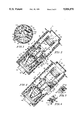
- FIG. 2 is a transverse sectional view of the filling control system, illustrating a slide member inside a fill passageway, a fill valve inside the fill passageway in its normally closed position, and two tank venting valves in their normally closed position;
- FIG. 3 is a sectional view taken along lines 3--3 of FIGS. 2, 4, and 7 illustrating the relative position of the two venting valves, a pressure/vacuum valve, a contaminant drain valve, a nozzle shutoff valve, and a nozzle shutoff tube surrounding the fill passageway;
- FIG. 4 is a view similar to FIG. 2 illustrating the position of the pressure/vacuum valve in its normally closed position
- FIG. 5 is a sectional view of the pressure/vacuum valve shown in FIG. 4 illustrating the pressure valve in its open position to vent fuel vapor from the fuel tank;
- FIG. 6 is a sectional view of the pressure/vacuum valve illustrating the vacuum valve in its open position to vent the atmospheric air into the fuel tank;
- FIG. 7 is an enlarged view illustrating the configuration of a closure member of the fill valve
- FIG. 8 is a transverse sectional view similar to FIGS. 2 and 4 illustrating the nozzle shutoff valve in its normally closed position and illustrating the contaminant drain valve in its normally open position;
- FIG. 9 is a plan view of the filling control system illustrating the "appearance" cover on the outer end of the filler neck;
- FIG. 10 is a transverse sectional view of the filling control system during refueling of the fuel tank illustrating a fuel nozzle inside the fill passageway to move the fill valve to its fill passageway-opening position, the nozzle shutoff valve in its open position, and the contaminant drain valve in its closed position;
- FIG. 11 is a sectional view similar to FIG. 10 illustrating the two tank venting valves in their open position when the fill valve is in the fill passageway-opening position;
- FIG. 12 is a sectional view similar to FIG. 11 illustrating operation of a fuel nozzle overtravel mechanism to accommodate a long pump nozzle;
- FIG. 13 is a transverse sectional view of a second embodiment of the present invention which includes an onboard fuel vapor recovery system;
- FIG. 14 is a view similar to FIG. 13 illustrating operation of the filling control system shown in FIG. 13 during refueling.
- FIG. 15 is a sectional view illustrating a retaining member for holding the pump nozzle in a proper position inside the fill passageway.
- the filling control system 10 of the present invention is schematically illustrated in the block diagram shown in FIG. 1.
- the filling control system 10 provides an assembly for controlling the refueling of a vehicle fuel tank 12 having a filler neck 14.
- Fuel tank 12 can also include a suitable roll-over valve 16.
- the filling control system 10 eliminates the need for conventional fuel caps.
- a fuel nozzle (not shown in FIG. 1) is inserted into the filling control system 10 in the direction of arrow 18.
- the filling control system 10 includes an appearance cover 20, a nozzle restrictor 22, a nozzle seal 24, a closure door seal 26, and a normally closed closure door 28 leading to a fill passageway 30.
- the fuel nozzle is inserted through the appearance cover 20 and through nozzle restrictor 22.
- Nozzle restrictor 22 permits only unleaded fuel nozzles to pass through the restrictor 22 into fill passageway 30.
- Nozzle seal 24 engages the outer periphery of the fuel nozzle to provide a seal.
- Closure door seal 26 provides a seal for closure door 28 when the closure door 28 is in its normally closed position during times other than refueling. Fuel nozzle moves closure door 28 from its normally closed position to an open position as it is inserted into the fill passageway 30.
- valve control apparatus 32 is connected to a fill valve 34 located in fill passageway 30.
- Fill valve 34 is a normally closed valve for closing or blocking the fill passageway 30 when the fuel nozzle is removed from the fill passageway 30.
- Fuel nozzle moves valve control apparatus 32 in the direction of arrow 36 to open fill valve 34. Fuel can then be dispensed through the open fill passageway 30 into filler neck 14 of fuel tank 12.
- a normally open contaminant drain valve 38 is provided to permit drainage of such contaminants from the fill passageway 30.
- Contaminant drain valve 38 remains in its normally open position when the fill valve 34 is in its normally closed position.
- drain contaminant valve 38 moves to a closed position to prevent fuel from escaping the fill passageway 30 through a drain aperture as best shown in FIG. 10.
- the filling control system 10 further includes a normally closed nozzle shutoff valve 40.
- a nozzle shutoff tube 42 interconnects the fuel tank 12 with a vent housing of filling control system 10.
- Nozzle shutoff valve 40 is a normally closed valve used to seal an end of the nozzle shutoff tube 42 inside the vent housing at times other than during refueling.
- valve control apparatus 32 moves nozzle shutoff valve 40 to an open position.
- Nozzle shutoff tube 42 provides make-up air to fill the interior region of the vent housing as fuel enters fuel tank 12. Once the level of fuel inside tank 12 rises above the end of nozzle shutoff tube 42 located inside fuel tank 12, a vacuum is created inside fill the interior region of vent housing which automatically shuts off the fuel nozzle. This feature is best shown in FIG. 10.
- the filling control system 10 also includes a normally closed tank venting valve 44 and a pressure/vacuum valve 46.
- a tank venting tube 48 connects the fuel tank 12 with a chamber inside the vent housing.
- Tank venting valve 44 is a normally closed valve to provide a seal between the atmosphere and the fuel tank 12 during times other than refueling of the fuel tank 12.
- valve control apparatus 32 moves fill valve 34 which moves tank venting valve 44 to an open position in response to introduction of the fuel nozzle into fill passageway 30.
- the open tank venting valve 44 vents fuel tank 12 to the atmosphere while the fuel nozzle dispenses fuel into tank 12 through filler neck 14. This feature is best shown in FIG. 11.
- the pressure/vacuum valve 46 is also normally closed. Pressure/vacuum valve 46 permits fuel vapor from fuel tank 12 to pass to the atmosphere when the pressure inside fuel tank 12 rises above a predetermined level. In addition, pressure/vacuum valve 46 vents atmospheric air into fuel tank 12 if the pressure within fuel tank 12 drops below a predetermined level.
- the pressure/vacuum valve is best shown in FIGS. 4-6.
- FIGS. 2, 4, and 8 illustrate the filling control system 10 in its "run position" at times other than during refueling of the fuel tank 12.
- Filling control system 10 includes a vent housing 50 defining an interior region 52 inside vent housing 50.
- a fuel nozzle housing 54 is located within interior region 52 to define fill passageway 30 within fuel nozzle housing 54. It is understood that fuel nozzle housing 54 and vent housing 50 may be formed integrally as a single unit.
- Nozzle actuated valve control apparatus or slide member 32 is situated within fill passageway 30.
- Slide member 32 includes a shaft portion 56 and a nozzle engaging portion 58 appended to a first end of shaft 56.
- a second end of slide member 32 is connected to a closure member 60 of fill valve 34.
- the closure member 60 provides the valve for opening and closing fill passageway 30. Closure member 60 is best illustrated in FIG. 7.
- Fuel nozzle housing 54 includes a partition 57 for dividing fill passageway 30 into an outer chamber 59 communicating with the atmosphere and an inner chamber 61 communicating with the fuel tank filler neck 14.
- Partition 57 is formed to include an aperture 63 interconnecting outer chamber 59 with inner chamber 61.
- Closure member 60 is situated in inner chamber 61 of fill passageway 30 and is configured to close the aperture 63 to block flow of fluid from outer chamber 59 to inner chamber 61 upon movement of fill valve 34 to its fill passageway-closing position illustrated in FIGS. 2, 4, and 8.
- a spring 69 biases fill valve 34 to its normally closed position. Spring 69 engages end wall 67 of vent housing 50 as shown in FIG. 2 to load closure member 60 against a valve seat on partition 57 surrounding aperture 63.
- Closure member 60 includes a generally conical base portion 62 and a generally spherical portion 64.
- Generally spherical portion 64 is formed to include a channel 66 for slidably receiving shaft 56 of slide member 32.
- a cross member 68 is connected to the second end of shaft 56 inside closure member 60 to retain shaft 56 within closure member 60.
- a resilient covering material 65 is situated over spherical portion 64 to provide a sealing surface on closure member 60. The covering material 65 extends through channel 66 to provide an annular valve seat 70 around shaft 56 and inside closure member 60. Valve seat 70 engages a cross member 68 connected to shaft 56 of slide member 32 to seal channel 66.
- a rigid biasing spring 72 is situated inside closure member 60 to bias slide member 32 towards opening 55 providing pump nozzle admitting means into fuel nozzle housing 54.
- Spring 72 is stronger than spring 69 for reasons explained below in connection with the nozzle overtravel feature shown in FIGS. 11 and 12.
- Covering material 65 engages valve seat 73 to close fill passageway 30.
- a dividing wall 80 is provided between vent housing 50 and fuel nozzle housing 54 to divide the annular region between vent housing 50 and fuel nozzle housing 54 into first and second annular chambers 82 and 84.
- the dividing wall 80 is formed to include a pair of first apertures 86 for interconnecting the first and second chambers 82 and 84 in fluid communication.
- the filling control system includes a first port 88 which provides an opening between the atmosphere and the first annular chamber 82 located in interior region 52 of vent housing 50.
- a second port opening 90 opens into the second chamber 84.
- Tank venting tube 48 is connected to second port 90 for communicating fuel vapor from the fuel tank 12 to the second chamber 84 through the second port 90.
- First and second venting valves 92 and 93 shown in FIG. 2 are provided for normally closing the first apertures 86 to block flow of fuel vapors from the fuel tank 12 to the atmosphere through the first and second chambers 82 and 84.
- Vent valves 92 and 93 include bias springs 94 and 95 for biasing vent valves 92 to their normally closed position shown in FIG. 2.
- Vent valves 92 and 93 are connected to actuator rods 96 and 98, respectively, by suitable fasteners 100 and 102.
- Actuator rods 96 and 98 are integrally connected to fill valve 34 as shown, for example, in FIG. 2.
- FIG. 3 illustrates the relative position of vent valves 92 and 93 spaced about fuel nozzle housing 54 inside vent housing 50.
- Dividing wall 86 is also formed to include a second aperture 110 for interconnecting first and second chambers 82 and 84.
- filling control system 10 includes a pressure/vacuum valve 46.
- Pressure/vacuum valve 46 includes a pressure valve 112 biased to a normally closed position by spring 114.
- Pressure vacuum valve 46 also includes a vacuum valve 116 biased to a normally closed position by spring 118.
- pressure valve 112 moves upwardly to the position shown in FIG. 5. This permits fuel vapor to vent from fuel tank 12 to the atmosphere in the direction of arrow 111 through aperture 110.
- vacuum valve 116 moves to the position shown in FIG. 6 to admit ambient air extant in first chamber 82 into second chamber 84 through the second aperture means 110. This occurs only when the pressure of fuel vapor in the second chamber 84 falls below a predetermined negative pressure.
- the position of the pressure/vacuum valve 46 relative to vent valves 92 and 93 inside vent housing 50 is best shown in FIG. 3.
- a drain contaminant valve 38 is provided, as best shown in FIG. 8. Contaminants entering interior region 52 of vent housing 50 pass in the direction of arrows 120.
- a drain passageway 122 is formed to extend from fill passageway 30 through fuel housing 54 and through vent housing 50 to the ground underneath the vehicle. As such, the outside end of drain passageway 122 is normally open to the atmosphere.
- Contaminant drain valve 38 includes a plunger 126 movable within a chamber 124.
- Plunger 126 includes a biasing spring 128 attached to a connector wall 130 extending between vent housing 50 and fuel nozzle housing 54.
- An actuator rod 134 on fill valve 34 engages plunger 126 and moves plunger 126 against the force of spring 128 to a normally open position to permit contaminants to pass through drain passageway 122 while fill valve 34 is in its normally closed position.
- the position of the contaminant drain valve 38 inside vent housing 50 is best shown in FIG. 3.
- FIG. 8 best illustrates closure door 28.
- Closure door 28 is coupled to a pivot arm 140.
- Pivot arm 140 is pivotably movable about a pivot shaft 142 to move closure door 28 from its normally closed position against closure door seal 26 to its open position.
- a spring biases pivot arm 140 to maintain closure door 28 in its normally closed position shown in FIG. 8.
- closure door pivots to its open position illustrated in FIG. 10.
- FIG. 8 further illustrates the configuration of nozzle shutoff valve 40 in its normally closed position.
- Nozzle shutoff valve 40 is connected to slide member 32 by a support arm 144.
- nozzle shutoff valve 40 engages and seals an end 146 of nozzle shutoff tube 42 which extends into interior region 52 of vent housing 50 through an aperture 148 in vent housing 50.
- the position of nozzle shutoff valve 40 and nozzle shutoff tube 42 inside vent housing 50 is best shown in FIG. 3.
- FIGS. 10-12 Operation of the filling control system 10 when system 10 is in its "fill position" during refueling is best illustrated in FIGS. 10-12.
- a fuel nozzle 75 is inserted into filling control system 10 through appearance cover 20.
- Appearance cover 20 is provided to give the outward appearance that the filler neck is closed to provide comfort to consumers unable to see the internal valve mechanisms provided inside the filler neck and is best shown in FIG. 9.
- Appearance cover 20 includes a plurality of sections 150 defining an opening 152 in appearance cover 20. Opening 152 is not aligned with the center of vent housing 50.
- Fuel nozzle 75 then enters interior region 52 of vent housing 50.
- Nozzle restrictor 22 permits entry of only an unleaded fuel nozzles 75 into fuel housing 54.
- Nozzle seal 24 engages the outer periphery of fuel nozzle 75 to seal the fuel nozzle 75.
- Fuel nozzle 75 engages closure door 28 and pivots closure door 28 about pivot shaft 142 to its open position shown in FIG. 10. Fuel nozzle 75 then contacts nozzle engaging member 58 of slide member 32. Fuel nozzle 75 moves the slide member 32 in the direction of arrow 154 to move closure member 60 of fill valve 34 against spring 69 and away from valve seat 73 to its fill passageway-opening position. This permits fuel to pass through aperture 63 formed in partition 57 from the outer chamber 59 to the inner chamber 61 of fill passageway 30. This permits fuel to be discharged from fuel nozzle 75 into filler neck 14.
- the drain passageway 122 is closed and sealed to permit development of a vacuum around the fuel nozzle during refueling as soon as the fuel level rises high enough in the tank to close the mouth of tube 42 and stop the flow of make-up vapor into the filler neck through the open nozzle shutoff valve.
- a normal fuel nozzle 75 provided at service stations includes an automatic shutoff feature which normally acts to shut off the flow of fuel from the fuel nozzle 75 when the fuel tank 12 is full.
- This shutoff feature is controlled by aspirator 156 provided in fuel nozzle 75 which shuts off the fuel nozzle 75 when a vacuum is created inside interior region 52 of vent housing 50.
- aspirator 156 provided in fuel nozzle 75 which shuts off the fuel nozzle 75 when a vacuum is created inside interior region 52 of vent housing 50.
- tank venting valves 92 and 93 are moved to the open position illustrated in FIG. 11 by actuator rods 96 and 98, respectively.
- the actuator rods 96 and 98 pull the tank venting valves 92 and 93 away from the first apertures 86. Therefore, the tank venting valves 92 and 93 open the pair of first apertures 86. This permits venting of fuel vapor from inside fuel tank 12 through tank venting tube 48, through second chamber 84, through first apertures 86, through first chambers 82, and through port 88 to the atmosphere during refueling.
- FIG. 12 illustrates the filling control system 10 in its run position, when a long fuel nozzle 75 is inserted into fuel nozzle housing 54.
- Spring 72 situated inside closure member 60 is a rigid spring, stronger than spring 69. Spring 72 normally maintains slide member 32 in the position shown in FIGS. 2, 4, 8, 10, and 11. However, when a long fuel nozzle 75 is inserted into fuel housing 54, the fuel nozzle 75 causes slide member 32 to slide through channel 66 of closure member 60 to move to the position shown in FIG. 12. Therefore, spring 72 permits slide member 32 to move relative to closure member 60 of fill valve 34 when a long fuel nozzle 75 is used.
- This provides a fuel nozzle 75 overtravel mechanism for the filling control system 10. The overtravel mechanism prevents damage to fill valve 34 when a long fuel nozzle 75 is used to refuel fuel tank 12.
- FIGS. 13-15 A second embodiment to the present invention is illustrated in FIGS. 13-15.
- the capless refueling system is configured to cooperate with an onboard fuel vapor recovery system shown diagrammatically in FIG. 13 to prevent fuel vapor from escape into the atmosphere during refueling.
- FIG. 13 illustrates the filling control system 210 in its run position.
- the filling control system 210 includes a vent housing 215 defining an interior region 220 within vent housing 215.
- a movable nozzle-retaining member 216 is provided to position fuel nozzle 75 properly inside the filling control system 210.
- Retaining member 216 is a self-actuated, spring-biased, nozzle latch to hold the nozzle 75 in the proper orientation for hands-off refueling.
- Interior region 220 provides a fill passageway 230 inside vent housing 215.
- a slide member 232 is situated inside fill passageway 230.
- a fill valve 234 is also situated inside fill passageway 230.
- Fill valve 234 is a normally closed valve which blocks flow of fluid through fill passageway 230 when filling control system 210 is in its run position shown in FIG. 13.
- Fuel valve 234 includes a body portion 236 and a ball portion 238.
- Vent housing 215 includes a partition 240 for dividing fill passageway 230 into an outer chamber 242 communicating with the atmosphere and an inner chamber 244 communicating with filler neck 214 of fuel tank 212.
- Partition 240 is formed to include an aperture 246 to provide fluid communication between the outer chamber 242 and the inner chamber 244.
- a valve seat 248 is coupled to partition 240 to provide a seal when fill valve 234 is in its fill passageway-closing position as shown in FIG. 13.
- Valve seat 248 abuts ball 238 of fill valve 234 to seal the fill passageway 230.
- Fill valve 234 is biased to its normally closed position by spring 250.
- An end of spring 250 abuts an end wall 252 of vent housing 215.
- a normally open contaminant drain valve 258 is also provided to remove contaminants which enter into interior region 220 when the filling control system 210 is in its run position.
- Contaminant drain valve 258 includes an actuator rod 260 and a sealing member or pad 262 coupled to a first end of the actuator rod 260.
- Contaminant drain valve 258 includes a drain passageway 264 extending through vent housing 215 to provide fluid communication between interior region 220 of vent housing 215 and the atmosphere when filling control system 210 is in its run position shown in FIG. 13.
- a second end of actuator rod 260 is coupled to a support arm 268 of slide member 232.
- a spring 266 biases the actuator arm to its extended position shown in FIG. 13.
- the filling control system 210 also includes a nozzle shut-off valve 270.
- Nozzle shut-off valve 270 seals an end 271 of nozzle shut-off tube 272 located inside interior region 220 when filling control system 210 is in its run position.
- Nozzle shut-off valve 270 includes a sealing member 274 coupled to a support arm 276 of slide member 232.
- FIG. 14 illustrates the filling control system 210 in its fill position.
- a nozzle 75 is inserted through nozzle restrictor 222, nozzle seal 224, and closure door seal 226.
- Nozzle 75 moves closure door 228 to its open position shown in FIG. 14 by pivoting the closure door 228 about pivot shaft 229.
- Fuel nozzle 75 then engages engaging member 254 of slide member 232 and moves the slide member in the direction of arrow 255.
- Shaft 256 of slide member 232 includes an end portion 257 which abuts ball 238 of fill valve 234.
- slide member 232 forces ball 238 fill valve 234 away from valve seat 248 against the force of spring 250 to open fill valve 234.
- Fuel is then permitted to be discharged from fuel nozzle 75 through outer chamber 242 and inner chamber 244 into filler neck 214.
- containment drain valve 258 moves to its closed position. Sealing pad 262 engages a wall 265 to cover and seal drain passageway 264. This blocks passage of fuel through drain passageway 264 during refueling.
- slide member 232 also opens nozzle shut-off valve 270. As shown in FIG. 14, seal 274 moves with slide member 232 away from opening 271 of nozzle shut-off tube 272. This provides an automatic shut-off feature as discussed above with reference to the first preferred embodiment.
- nozzle-retaining member 216 is provided to hold nozzle 75 in a proper position within interior region 220.
- Nozzle-retaining member 216 is biased toward the nozzle 75 by a spring 217 and engages, for example, a collar 219 provided on nozzle 75 to hold nozzle 75 in a proper position during refueling.
- Filling control system 210 also includes a vapor recovery system 280.
- Vapor recovery system 280 includes a venting valve 282 and an overfill shut-off valve 286 connected to venting valve 282 by vapor flow passage. 284.
- Overfill shut-off valve hose 294 connects overfill shut-off valve 286 to fuel tank 212.
- Venting valve 282 is at least partially controlled by an actuation conduit 281 coupled to vent housing 215.
- Vapor recovery system 280 acts to control the flow of fuel vapor from fuel tank 212 to a conventional canister 290 through a fuel vapor discharge hose 292.
- the canister 290 acts as a fuel vapor treatment site for treating and controlling fuel vapor routed thereto.
- the canister 290 is a conventional charcoal canister or other vapor condenser which adsorbs liquid fuel entrained in the recovered fuel vapor on a substrate to permit recombustion within the vehicle engine (not shown). Details of the operation of vapor recovery system 280 are discussed in U.S. Pat. No. 4,816,045 which is assigned to the assignee of the present invention.
- valve assembly 300 for controlling the flow of air from the atmosphere to actuation conduit 281 and the flow of fuel vapor from tank tube 296 to actuation conduit 281 is shown in FIGS. 13 and 14 to control operation of the onboard fuel vapor recovery system automatically.
- Valve assembly 300 is shown to include a valve 302 and bias means 304 for yieldably moving valve 302 between a "run" position shown in FIG. 13 and a "refueling" position as shown in FIG. 14.
- a transfer tube 306 is provided for communicating ambient air to the valve 302 as shown in FIGS. 13 and 14.
- a pair of sealing rings 308 are provided for establishing a seal between valve 302 and the wall defining the channel 310 in which valve 302 is free to reciprocate.
- Valve 302 is formed to include several interior passageways situated to interconnect selected pairs of tubes 281, 296, and 306 as a function of the position of valve 302 in channel 310 to control the operation of the tank venting system via module 280.
- the valve 302 is formed to include an axial passageway 312 and a transverse passageway 314 interconnecting axial passageway 312 at a junction inside valve 302.
- passageways 312 and 314 normally cooperate to interconnect tubes 281 and 296 in fluid communication so that fuel vapor is conducted from fuel tank 212 to venting valve 282 so that venting valve 282 will be exposed to tank pressure on both sides. In such a condition, venting valve 282 will remain closed to block flow of fuel vapor from the fuel tank 212 to the canister 290 as explained in greater detail in U.S. Pat. No. 4,816,045.
- venting valve 282 is exposed to a pressure imbalance because it sees tank pressure in tube 284 and atmospheric pressure in tube 281 causing the venting valve 282 to move to a venting or open position permitting fuel vapor to be conducted past venting valve 282 from fuel tank 212 to canister 290.
- the filling control system 210 also includes a safety bypass valve 298. Upon failure of the fuel nozzle 75 to shut-off, bypass valve 298 is activated to divert fuel through hose 300 so that the fuel swirls in the upper portion of the interior region 220 of vent housing 215 to alert the user to shut the fuel nozzle 75 off.
Abstract
Description
Claims (36)
Priority Applications (3)
| Application Number | Priority Date | Filing Date | Title |
|---|---|---|---|
| US07/498,612 US5056570A (en) | 1990-03-26 | 1990-03-26 | Capless vehicle refueling system |
| DE4109337A DE4109337A1 (en) | 1990-03-26 | 1991-03-19 | CAPLESS VEHICLE REFUELING DEVICE |
| JP3083021A JPH04224420A (en) | 1990-03-26 | 1991-03-25 | Cap-less car fuel supply system |
Applications Claiming Priority (1)
| Application Number | Priority Date | Filing Date | Title |
|---|---|---|---|
| US07/498,612 US5056570A (en) | 1990-03-26 | 1990-03-26 | Capless vehicle refueling system |
Publications (1)
| Publication Number | Publication Date |
|---|---|
| US5056570A true US5056570A (en) | 1991-10-15 |
Family
ID=23981783
Family Applications (1)
| Application Number | Title | Priority Date | Filing Date |
|---|---|---|---|
| US07/498,612 Expired - Lifetime US5056570A (en) | 1990-03-26 | 1990-03-26 | Capless vehicle refueling system |
Country Status (3)
| Country | Link |
|---|---|
| US (1) | US5056570A (en) |
| JP (1) | JPH04224420A (en) |
| DE (1) | DE4109337A1 (en) |
Cited By (75)
| Publication number | Priority date | Publication date | Assignee | Title |
|---|---|---|---|---|
| US5195566A (en) * | 1991-05-01 | 1993-03-23 | Mecrom Ott & Holey Ohg | Cap for the filler neck of liquid containers |
| US5271438A (en) * | 1992-06-22 | 1993-12-21 | Stant Manufacturing Inc. | Capless vehicle refueling system with moving fill passageway |
| US5282499A (en) * | 1992-08-27 | 1994-02-01 | General Motors Corporation | Remote reservoir filler |
| US5291924A (en) * | 1990-10-30 | 1994-03-08 | Firma Carl Freudenberg | Sealing system for use in the filler neck of a fuel tank |
| US5320147A (en) * | 1993-05-06 | 1994-06-14 | Ford Motor Company | Fuel filler pipe fill control module |
| US5398737A (en) * | 1992-07-10 | 1995-03-21 | Instrumentarium Corporation | Connecting mechanism |
| US5431199A (en) * | 1993-11-30 | 1995-07-11 | Benjey, Robert P | Redundant seal for vehicle filler neck |
| US5437317A (en) * | 1993-02-04 | 1995-08-01 | Om Corporation | Ventilation line opening/closing means of fuel tank |
| US5474048A (en) * | 1993-12-24 | 1995-12-12 | Honda Giken Kogyo Kabushiki Kaisha | Evaporative fuel-processing system for internal combustion engines |
| WO1996033095A1 (en) | 1995-04-21 | 1996-10-24 | Stant Manufacturing Inc. | Closure assembly for a tank filler neck |
| US5568828A (en) * | 1994-11-30 | 1996-10-29 | Stant Manufacturing Inc. | Fuel-delivery control system |
| USD381004S (en) * | 1995-04-21 | 1997-07-15 | Stant Manufacturing Inc. | Shroud for a filler neck crown assembly |
| US5730194A (en) * | 1996-03-21 | 1998-03-24 | Stant Manufacturing Inc. | Capless filler neck closure system |
| USD403643S (en) * | 1996-10-24 | 1999-01-05 | Stant Manufacturing Inc. | Filler neck crown assembly |
| US5860460A (en) * | 1995-03-03 | 1999-01-19 | Honda Giken Kogyo Kabushiki Kaisha | Refueling pipe structure in fuel tank |
| WO1999003697A1 (en) | 1997-07-17 | 1999-01-28 | Tesma International Inc. | Capless refueling assembly |
| US5921424A (en) * | 1995-11-21 | 1999-07-13 | Blau Internatiional Gesmbh | Closure device for a vehicle tank filler neck |
| US5944075A (en) * | 1998-02-06 | 1999-08-31 | Turner; Delwin James | Removable quick-fill fuel cap |
| US5960839A (en) * | 1998-08-05 | 1999-10-05 | Ford Global Technologies, Inc. | Fuel tank system |
| US6056029A (en) * | 1999-03-03 | 2000-05-02 | Stant Manufacturing Inc. | Fuel-Transfer system |
| US6092685A (en) * | 1997-10-16 | 2000-07-25 | Tesma International Inc. | Capless refueling assembly |
| US6189581B1 (en) | 1998-05-08 | 2001-02-20 | Stant Manufacturing Inc. | Filler neck closure |
| US6250348B1 (en) | 1999-01-29 | 2001-06-26 | J. C. Carter Company, Inc. | Refueling nozzle |
| US6311741B1 (en) | 2000-03-29 | 2001-11-06 | Ford Global Technologies, Inc | Fuel tank fuel vapor emission control through air ingestion reduction |
| USRE37776E1 (en) * | 1995-04-21 | 2002-07-02 | Stant Manufacturing Inc. | Closure assembly for a tank filler neck |
| US6446826B1 (en) | 1997-02-11 | 2002-09-10 | Stant Manufacturing Inc. | Seal for filler neck closure assembly |
| US6546972B1 (en) | 2001-11-21 | 2003-04-15 | Stant Manufacturing Inc. | Filler neck for a fuel system |
| US20040000554A1 (en) * | 2002-05-01 | 2004-01-01 | Jeffery Griffin | Static charge dissipater for filler neck closure |
| US6691750B1 (en) | 2002-11-04 | 2004-02-17 | Stant Manufacturing Inc. | Floating nozzle collar for capless filler neck |
| US6698475B2 (en) * | 2000-12-19 | 2004-03-02 | Kautex Textron Gmbh & Co. Kg | Fuel tank |
| US20040074556A1 (en) * | 1999-12-03 | 2004-04-22 | O'connell Patrick R. | Fuel tank filler neck and method of manufacturing same |
| US6755057B2 (en) * | 2002-11-04 | 2004-06-29 | Stant Manufacturing Inc. | Dust cover lock system for vehicle filler neck |
| US20040163732A1 (en) * | 2003-02-21 | 2004-08-26 | Rainer Gramss | Closing device for a filling tube of a fuel tank in an automobile |
| US6789586B2 (en) | 2001-11-20 | 2004-09-14 | Illinois Tool Works Inc. | Breakaway capless refueling assembly |
| US6880593B1 (en) * | 2003-12-10 | 2005-04-19 | Dayco Products, Llc | Fuel fill system |
| US20050115636A1 (en) * | 2002-02-04 | 2005-06-02 | Nobel Plastiques | Head for a fuel tank filler neck |
| US20050155671A1 (en) * | 2004-01-15 | 2005-07-21 | Mcclung Chad A. | Closure and vent system for capless filler neck |
| US6968874B1 (en) | 2004-10-07 | 2005-11-29 | Martinrea Industries, Inc. | Capless automotive fueling system |
| US20050263211A1 (en) * | 2004-05-28 | 2005-12-01 | Mccracken Douglas D | Fuel filler neck assembly and method of fabricating |
| US6983773B1 (en) * | 2000-09-27 | 2006-01-10 | Toyoda Gosei Co., Ltd. | Oil feeder of fuel tank |
| US20060065325A1 (en) * | 1999-12-03 | 2006-03-30 | O'connell Patrick R | Fuel tank filler neck and method of manufacturing same |
| US7028727B1 (en) * | 2002-12-09 | 2006-04-18 | Saint Technologies, Inc. | Easy use valved fluid container assembly and valve system for same |
| US7048019B2 (en) | 2003-09-30 | 2006-05-23 | Shelby Enterprises, Inc. | Fuel filler tube assembly and manufacturing method |
| US7055557B1 (en) * | 2005-03-03 | 2006-06-06 | Eaton Corporation | Dual seal filler neck with air relief valve |
| WO2006066294A1 (en) * | 2004-12-20 | 2006-06-29 | Tesma Motoren- Und Getriebetechnik Gmbh | Cap-free filler pipe for the tank of a motor vehicle |
| US20070163672A1 (en) * | 2003-12-08 | 2007-07-19 | Matt Luntz | Automatic shutoff refueling receiver |
| US20070209733A1 (en) * | 2006-03-09 | 2007-09-13 | Honda Motor Co., Ltd. | High flow fuel inlet pipe |
| US20070261757A1 (en) * | 2005-12-29 | 2007-11-15 | Smith Gregory F | Filler tube assembly |
| US20080000544A1 (en) * | 2006-06-28 | 2008-01-03 | Ford Global Technologies, Llc | Fuel filler nozzle for automotive vehicle |
| DE102006056553A1 (en) * | 2006-07-31 | 2008-02-21 | Alfmeier Präzision AG Baugruppen und Systemlösungen | Filler neck for the fuel tank of a motor vehicle |
| US20080237230A1 (en) * | 2004-01-19 | 2008-10-02 | Itw Automotive Products Gmbh & Co. Kg | Filler Neck to Fill Fuel Into a Vehicle Tank |
| US20080237231A1 (en) * | 2007-03-27 | 2008-10-02 | Magna Steyr Fuel Systems Gesmbh | Filler neck of a fuel tank with an arrangement for preventing incorrect fueling |
| US20080295906A1 (en) * | 2007-05-29 | 2008-12-04 | Mccracken Douglas D | Fuel filler neck assembly and method of fabricating |
| US20100224282A1 (en) * | 2009-02-26 | 2010-09-09 | Magna Steyr Fuel Systems Gesmbh | Filler head for a fuel tank having a protective device |
| US20110011860A1 (en) * | 2005-12-29 | 2011-01-20 | Smith Gregory F | Filler tube assembly |
| WO2012020313A2 (en) * | 2010-08-11 | 2012-02-16 | Emco Wheaton Corp. | Adaptor for fluid tank |
| US20120234302A1 (en) * | 2011-03-16 | 2012-09-20 | Takeshi Shimura | Evaporative fuel treatment apparatus of vehicle |
| US20120298213A1 (en) * | 2010-01-14 | 2012-11-29 | Tiss Limited | Anti siphon device |
| US20130075395A1 (en) * | 2011-09-27 | 2013-03-28 | Toyoda Gosei Co., Ltd. | Fuel tank opening-closing device |
| US20130313818A1 (en) * | 2012-04-27 | 2013-11-28 | Leigh Maxwell Remfry | Refueling Coupling |
| US8662118B2 (en) | 2011-12-01 | 2014-03-04 | Emco Wheaton Corp. | Liquid filling system |
| US8701694B2 (en) | 2011-03-10 | 2014-04-22 | Stant Usa Corp. | Mount for inlet check valve |
| US20140216563A1 (en) * | 2013-02-06 | 2014-08-07 | Ford Global Technologies, Llc | Capless refueling system cleaning using engine vacuum |
| US9022053B2 (en) | 2011-03-10 | 2015-05-05 | Stant Usa Corp. | Mount for inlet check valve |
| US9067487B2 (en) | 2012-08-30 | 2015-06-30 | Fca Us Llc | Collapsible fuel door housing for a vehicle |
| US20150337775A1 (en) * | 2014-05-21 | 2015-11-26 | Ford Global Technologies, Llc | System and methods for purging a fuel vapor canister buffer |
| US20160001653A1 (en) * | 2013-02-26 | 2016-01-07 | Illinois Tool Works Inc. | Draining fuel nozzle-receiving assembly |
| US9434248B2 (en) * | 2012-09-28 | 2016-09-06 | Toyoda Gosei Co., Ltd. | Fuel tank opening and closing device |
| US9457650B2 (en) * | 2012-08-28 | 2016-10-04 | Ford Global Technologies, Llc | Drain slot for capless fuel filler insert |
| US9850119B2 (en) * | 2016-03-16 | 2017-12-26 | Blend-Rite Industries, Inc. | Automatic truck tank fill system |
| US10000117B2 (en) * | 2012-02-17 | 2018-06-19 | Stant Usa Corp. | Filler neck closure assembly |
| US20180229599A1 (en) * | 2017-02-16 | 2018-08-16 | Toyoda Gosei Co., Ltd. | Fuel supply device |
| US20180272861A1 (en) * | 2017-03-22 | 2018-09-27 | Denso Corporation | Fuel tank system |
| US10675970B2 (en) | 2016-08-15 | 2020-06-09 | Ford Global Technologies, Llc | Vehicle capless refueling system |
| US20220089018A1 (en) * | 2020-09-23 | 2022-03-24 | Hyundai Motor Company | Apparatus for controlling shut-off of fuel gun in filler pipe of fuel tank |
Families Citing this family (10)
| Publication number | Priority date | Publication date | Assignee | Title |
|---|---|---|---|---|
| DE4223081C2 (en) * | 1992-07-14 | 1997-03-13 | Kaco Gmbh Co | Sealing device for a filler neck of a motor vehicle |
| CA2102569A1 (en) * | 1993-11-05 | 1995-05-06 | Stanley Robert Elsdon | Automatic shut-off valve arrangement |
| FR2730675B1 (en) * | 1995-02-21 | 1997-04-04 | Journee Paul Sa | DEVICE FOR FILLING A FUEL TANK FOR A MOTOR VEHICLE PROVIDED WITH A FUEL VAPOR RECOVERY DEVICE |
| FR2740739B1 (en) * | 1995-11-08 | 1997-12-05 | Journee Paul Sa | IMPROVED DEVICE FOR FILLING A MOTOR VEHICLE FUEL TANK |
| AT1595U1 (en) * | 1996-07-03 | 1997-08-25 | Blau Automobiltechnik Gmbh | MULTI-FUNCTION VALVE FOR A FUEL TANK FILLER |
| DE19747986C2 (en) | 1997-10-30 | 2002-09-12 | Bosch Gmbh Robert | Cap for a tank |
| DE10110189B4 (en) * | 2001-03-02 | 2009-07-09 | Kautex Textron Gmbh & Co. Kg | Fuel tank |
| DE10352767A1 (en) | 2003-11-12 | 2005-06-23 | Alfred Engelmann Holding Gmbh | Closing device for a tank access opening, in particular for filler neck in motor vehicles |
| ES2314579T3 (en) * | 2005-02-10 | 2009-03-16 | Gerdes Gmbh | REMOVABLE FITTING FITTING WITHOUT COVER FOR FILLING FITTING OF A DEPOSIT OF A MOTOR VEHICLE. |
| JP6702123B2 (en) * | 2016-09-30 | 2020-05-27 | 豊田合成株式会社 | Refueling device |
Citations (36)
| Publication number | Priority date | Publication date | Assignee | Title |
|---|---|---|---|---|
| US3289711A (en) * | 1965-12-13 | 1966-12-06 | Walker Brooks | Device for controlling the hydrocarbon evaporation losses from automotive vehicles |
| US3477611A (en) * | 1968-04-03 | 1969-11-11 | Ford Motor Co | Fuel tank having reduced fuel vapor emission |
| US3543484A (en) * | 1968-05-24 | 1970-12-01 | Edwin R Davis | Fuel vapor adsorbing apparatus |
| US3643690A (en) * | 1969-09-13 | 1972-02-22 | Toyota Motor Co Ltd | Vented fuel tank |
| US3748829A (en) * | 1970-07-02 | 1973-07-31 | Calgon Corp | Adsorbing evaporative emission during fueling of automotive vehicles |
| US3763901A (en) * | 1971-01-25 | 1973-10-09 | C Viland | Method of preventing loss of hydrocarbons to atmosphere |
| US3884204A (en) * | 1974-04-15 | 1975-05-20 | Gen Motors Corp | Tank fill vapor control |
| US3907153A (en) * | 1974-02-19 | 1975-09-23 | Gen Motors Corp | Fuel tank venting system |
| US3911977A (en) * | 1973-09-14 | 1975-10-14 | Peugeot | Filler pipe end structure, in particular for vehicle tank |
| US3921412A (en) * | 1974-07-18 | 1975-11-25 | Rohr Industries Inc | Vapor recovery apparatus employing dispensing nozzle with condensing capacity |
| US3938564A (en) * | 1975-01-06 | 1976-02-17 | Kaiser Aerospace And Electronics Corporation | Quick-release fuel coupling for racing cars |
| US4122968A (en) * | 1976-11-10 | 1978-10-31 | The Goodyear Tire & Rubber Company | Vapor recovery filler neck assembly |
| US4142647A (en) * | 1977-12-15 | 1979-03-06 | General Motors Corporation | Fuel tank venting system |
| US4232715A (en) * | 1978-12-28 | 1980-11-11 | Chevron Research Company | Coaxial vapor recovery nozzle |
| US4312649A (en) * | 1979-01-09 | 1982-01-26 | Kawaski Jukogyo Kabushiki Kaisha | Fuel vapor arresting means for motorcycle engine fuel system |
| US4420392A (en) * | 1981-03-06 | 1983-12-13 | Stant Inc. | Fuel-water separator with flow-reduction feature |
| US4424839A (en) * | 1980-01-22 | 1984-01-10 | Honda Giken Kogyo Kabushiki Kaisha | Inlet for a fuel tank |
| US4441533A (en) * | 1978-12-04 | 1984-04-10 | Snyder George H | Automatic fuel dispenser |
| US4630749A (en) * | 1986-03-18 | 1986-12-23 | General Motors Corporation | Fuel fill tube with vapor vent and overfill protection |
| US4651889A (en) * | 1984-03-23 | 1987-03-24 | Toyota Jidosha Kabushiki Kaisha | Fuel tank nozzle having a dual purpose valve |
| US4694847A (en) * | 1986-03-07 | 1987-09-22 | Stant Inc. | Roll-over valve with sealing ball |
| US4699638A (en) * | 1986-03-31 | 1987-10-13 | Stant Inc. | Two-stage roll-over valve |
| US4701198A (en) * | 1984-03-24 | 1987-10-20 | Toyota Jidosha Kabushiki Kaisha | Fuel tank for use in a motor vehicle |
| US4702386A (en) * | 1986-06-06 | 1987-10-27 | Vernay Laboratories, Inc. | Fuel filler pipe seal |
| US4714172A (en) * | 1986-12-23 | 1987-12-22 | Gt Development Corporation | Vapor recovery systems |
| US4722454A (en) * | 1985-11-16 | 1988-02-02 | Dr. Ing. H.C.F Porsche Aktiengesellschaft | Filler inlet for a fuel tank, particularly for motor vehicles |
| US4741369A (en) * | 1987-02-12 | 1988-05-03 | Chrysler Motors Corporation | Inletting device for fuel tank |
| US4747508A (en) * | 1987-03-09 | 1988-05-31 | General Motors Corporation | Fuel tank venting |
| US4765504A (en) * | 1987-08-31 | 1988-08-23 | General Motors Corporation | Vapor venting valve for vehicle fuel system |
| US4770677A (en) * | 1986-03-31 | 1988-09-13 | Stant Inc. | Vapor recovery system |
| US4809863A (en) * | 1987-10-16 | 1989-03-07 | Colt Industries Inc | Fill neck assembly for on board refueling vapor recovery system |
| US4816045A (en) * | 1986-03-31 | 1989-03-28 | Stant Inc. | Vapor recovery system |
| US4826511A (en) * | 1986-03-31 | 1989-05-02 | Stant Inc. | Vapor recovery system |
| US4836835A (en) * | 1986-03-31 | 1989-06-06 | Stant Inc. | Vacuum-actuated vapor recovery system |
| US4877146A (en) * | 1986-03-31 | 1989-10-31 | Stant Inc. | Vacuum-controlled vapor recovery system |
| US4883103A (en) * | 1986-03-31 | 1989-11-28 | Stant Inc. | Filler neck sealing assembly |
-
1990
- 1990-03-26 US US07/498,612 patent/US5056570A/en not_active Expired - Lifetime
-
1991
- 1991-03-19 DE DE4109337A patent/DE4109337A1/en not_active Withdrawn
- 1991-03-25 JP JP3083021A patent/JPH04224420A/en active Pending
Patent Citations (36)
| Publication number | Priority date | Publication date | Assignee | Title |
|---|---|---|---|---|
| US3289711A (en) * | 1965-12-13 | 1966-12-06 | Walker Brooks | Device for controlling the hydrocarbon evaporation losses from automotive vehicles |
| US3477611A (en) * | 1968-04-03 | 1969-11-11 | Ford Motor Co | Fuel tank having reduced fuel vapor emission |
| US3543484A (en) * | 1968-05-24 | 1970-12-01 | Edwin R Davis | Fuel vapor adsorbing apparatus |
| US3643690A (en) * | 1969-09-13 | 1972-02-22 | Toyota Motor Co Ltd | Vented fuel tank |
| US3748829A (en) * | 1970-07-02 | 1973-07-31 | Calgon Corp | Adsorbing evaporative emission during fueling of automotive vehicles |
| US3763901A (en) * | 1971-01-25 | 1973-10-09 | C Viland | Method of preventing loss of hydrocarbons to atmosphere |
| US3911977A (en) * | 1973-09-14 | 1975-10-14 | Peugeot | Filler pipe end structure, in particular for vehicle tank |
| US3907153A (en) * | 1974-02-19 | 1975-09-23 | Gen Motors Corp | Fuel tank venting system |
| US3884204A (en) * | 1974-04-15 | 1975-05-20 | Gen Motors Corp | Tank fill vapor control |
| US3921412A (en) * | 1974-07-18 | 1975-11-25 | Rohr Industries Inc | Vapor recovery apparatus employing dispensing nozzle with condensing capacity |
| US3938564A (en) * | 1975-01-06 | 1976-02-17 | Kaiser Aerospace And Electronics Corporation | Quick-release fuel coupling for racing cars |
| US4122968A (en) * | 1976-11-10 | 1978-10-31 | The Goodyear Tire & Rubber Company | Vapor recovery filler neck assembly |
| US4142647A (en) * | 1977-12-15 | 1979-03-06 | General Motors Corporation | Fuel tank venting system |
| US4441533A (en) * | 1978-12-04 | 1984-04-10 | Snyder George H | Automatic fuel dispenser |
| US4232715A (en) * | 1978-12-28 | 1980-11-11 | Chevron Research Company | Coaxial vapor recovery nozzle |
| US4312649A (en) * | 1979-01-09 | 1982-01-26 | Kawaski Jukogyo Kabushiki Kaisha | Fuel vapor arresting means for motorcycle engine fuel system |
| US4424839A (en) * | 1980-01-22 | 1984-01-10 | Honda Giken Kogyo Kabushiki Kaisha | Inlet for a fuel tank |
| US4420392A (en) * | 1981-03-06 | 1983-12-13 | Stant Inc. | Fuel-water separator with flow-reduction feature |
| US4651889A (en) * | 1984-03-23 | 1987-03-24 | Toyota Jidosha Kabushiki Kaisha | Fuel tank nozzle having a dual purpose valve |
| US4701198A (en) * | 1984-03-24 | 1987-10-20 | Toyota Jidosha Kabushiki Kaisha | Fuel tank for use in a motor vehicle |
| US4722454A (en) * | 1985-11-16 | 1988-02-02 | Dr. Ing. H.C.F Porsche Aktiengesellschaft | Filler inlet for a fuel tank, particularly for motor vehicles |
| US4694847A (en) * | 1986-03-07 | 1987-09-22 | Stant Inc. | Roll-over valve with sealing ball |
| US4630749A (en) * | 1986-03-18 | 1986-12-23 | General Motors Corporation | Fuel fill tube with vapor vent and overfill protection |
| US4826511A (en) * | 1986-03-31 | 1989-05-02 | Stant Inc. | Vapor recovery system |
| US4699638A (en) * | 1986-03-31 | 1987-10-13 | Stant Inc. | Two-stage roll-over valve |
| US4770677A (en) * | 1986-03-31 | 1988-09-13 | Stant Inc. | Vapor recovery system |
| US4816045A (en) * | 1986-03-31 | 1989-03-28 | Stant Inc. | Vapor recovery system |
| US4836835A (en) * | 1986-03-31 | 1989-06-06 | Stant Inc. | Vacuum-actuated vapor recovery system |
| US4877146A (en) * | 1986-03-31 | 1989-10-31 | Stant Inc. | Vacuum-controlled vapor recovery system |
| US4883103A (en) * | 1986-03-31 | 1989-11-28 | Stant Inc. | Filler neck sealing assembly |
| US4702386A (en) * | 1986-06-06 | 1987-10-27 | Vernay Laboratories, Inc. | Fuel filler pipe seal |
| US4714172A (en) * | 1986-12-23 | 1987-12-22 | Gt Development Corporation | Vapor recovery systems |
| US4741369A (en) * | 1987-02-12 | 1988-05-03 | Chrysler Motors Corporation | Inletting device for fuel tank |
| US4747508A (en) * | 1987-03-09 | 1988-05-31 | General Motors Corporation | Fuel tank venting |
| US4765504A (en) * | 1987-08-31 | 1988-08-23 | General Motors Corporation | Vapor venting valve for vehicle fuel system |
| US4809863A (en) * | 1987-10-16 | 1989-03-07 | Colt Industries Inc | Fill neck assembly for on board refueling vapor recovery system |
Cited By (116)
| Publication number | Priority date | Publication date | Assignee | Title |
|---|---|---|---|---|
| US5291924A (en) * | 1990-10-30 | 1994-03-08 | Firma Carl Freudenberg | Sealing system for use in the filler neck of a fuel tank |
| US5195566A (en) * | 1991-05-01 | 1993-03-23 | Mecrom Ott & Holey Ohg | Cap for the filler neck of liquid containers |
| US5271438A (en) * | 1992-06-22 | 1993-12-21 | Stant Manufacturing Inc. | Capless vehicle refueling system with moving fill passageway |
| WO1994000351A1 (en) * | 1992-06-22 | 1994-01-06 | Stant Manufacturing Inc. | Capless refueling system with moving fill passageway |
| US5398737A (en) * | 1992-07-10 | 1995-03-21 | Instrumentarium Corporation | Connecting mechanism |
| US5282499A (en) * | 1992-08-27 | 1994-02-01 | General Motors Corporation | Remote reservoir filler |
| US5437317A (en) * | 1993-02-04 | 1995-08-01 | Om Corporation | Ventilation line opening/closing means of fuel tank |
| US5320147A (en) * | 1993-05-06 | 1994-06-14 | Ford Motor Company | Fuel filler pipe fill control module |
| US5431199A (en) * | 1993-11-30 | 1995-07-11 | Benjey, Robert P | Redundant seal for vehicle filler neck |
| US5474048A (en) * | 1993-12-24 | 1995-12-12 | Honda Giken Kogyo Kabushiki Kaisha | Evaporative fuel-processing system for internal combustion engines |
| US5568828A (en) * | 1994-11-30 | 1996-10-29 | Stant Manufacturing Inc. | Fuel-delivery control system |
| US5860460A (en) * | 1995-03-03 | 1999-01-19 | Honda Giken Kogyo Kabushiki Kaisha | Refueling pipe structure in fuel tank |
| USRE37776E1 (en) * | 1995-04-21 | 2002-07-02 | Stant Manufacturing Inc. | Closure assembly for a tank filler neck |
| US5732840A (en) * | 1995-04-21 | 1998-03-31 | Stant Manufacturing Inc. | Closure assembly for a tank filler neck |
| USD381004S (en) * | 1995-04-21 | 1997-07-15 | Stant Manufacturing Inc. | Shroud for a filler neck crown assembly |
| WO1996033095A1 (en) | 1995-04-21 | 1996-10-24 | Stant Manufacturing Inc. | Closure assembly for a tank filler neck |
| US5921424A (en) * | 1995-11-21 | 1999-07-13 | Blau Internatiional Gesmbh | Closure device for a vehicle tank filler neck |
| US5730194A (en) * | 1996-03-21 | 1998-03-24 | Stant Manufacturing Inc. | Capless filler neck closure system |
| USD403643S (en) * | 1996-10-24 | 1999-01-05 | Stant Manufacturing Inc. | Filler neck crown assembly |
| US6446826B1 (en) | 1997-02-11 | 2002-09-10 | Stant Manufacturing Inc. | Seal for filler neck closure assembly |
| WO1999003697A1 (en) | 1997-07-17 | 1999-01-28 | Tesma International Inc. | Capless refueling assembly |
| US6009920A (en) * | 1997-07-17 | 2000-01-04 | Tesma International Inc. | Capless refueling assembly |
| US6092685A (en) * | 1997-10-16 | 2000-07-25 | Tesma International Inc. | Capless refueling assembly |
| US5944075A (en) * | 1998-02-06 | 1999-08-31 | Turner; Delwin James | Removable quick-fill fuel cap |
| US6189581B1 (en) | 1998-05-08 | 2001-02-20 | Stant Manufacturing Inc. | Filler neck closure |
| US5960839A (en) * | 1998-08-05 | 1999-10-05 | Ford Global Technologies, Inc. | Fuel tank system |
| US6250348B1 (en) | 1999-01-29 | 2001-06-26 | J. C. Carter Company, Inc. | Refueling nozzle |
| US6056029A (en) * | 1999-03-03 | 2000-05-02 | Stant Manufacturing Inc. | Fuel-Transfer system |
| US20060065325A1 (en) * | 1999-12-03 | 2006-03-30 | O'connell Patrick R | Fuel tank filler neck and method of manufacturing same |
| US20080128415A1 (en) * | 1999-12-03 | 2008-06-05 | Shelby Enterprises, Inc. | Fuel tank filler neck and method of manufacturing same |
| US7343942B2 (en) | 1999-12-03 | 2008-03-18 | Shelby Enterprises, Inc. | Fuel tank filler neck and method of manufacturing same |
| US7059365B2 (en) | 1999-12-03 | 2006-06-13 | Shelby Enterprises, Inc. | Fuel tank filler neck and method of manufacturing same |
| US20040074556A1 (en) * | 1999-12-03 | 2004-04-22 | O'connell Patrick R. | Fuel tank filler neck and method of manufacturing same |
| US6311741B1 (en) | 2000-03-29 | 2001-11-06 | Ford Global Technologies, Inc | Fuel tank fuel vapor emission control through air ingestion reduction |
| US6983773B1 (en) * | 2000-09-27 | 2006-01-10 | Toyoda Gosei Co., Ltd. | Oil feeder of fuel tank |
| US6698475B2 (en) * | 2000-12-19 | 2004-03-02 | Kautex Textron Gmbh & Co. Kg | Fuel tank |
| US6789586B2 (en) | 2001-11-20 | 2004-09-14 | Illinois Tool Works Inc. | Breakaway capless refueling assembly |
| EP1314606A2 (en) | 2001-11-21 | 2003-05-28 | Stant Manufacturing Inc. | Filler neck for a fuel system |
| US6546972B1 (en) | 2001-11-21 | 2003-04-15 | Stant Manufacturing Inc. | Filler neck for a fuel system |
| US20050115636A1 (en) * | 2002-02-04 | 2005-06-02 | Nobel Plastiques | Head for a fuel tank filler neck |
| US20050003095A1 (en) * | 2002-05-01 | 2005-01-06 | Jeffery Griffin | Method for making a filler neck closure |
| US20040000554A1 (en) * | 2002-05-01 | 2004-01-01 | Jeffery Griffin | Static charge dissipater for filler neck closure |
| US7163117B2 (en) | 2002-05-01 | 2007-01-16 | Stant Manufacturing Inc. | Static charge dissipater for filler neck closure |
| US6691750B1 (en) | 2002-11-04 | 2004-02-17 | Stant Manufacturing Inc. | Floating nozzle collar for capless filler neck |
| US6755057B2 (en) * | 2002-11-04 | 2004-06-29 | Stant Manufacturing Inc. | Dust cover lock system for vehicle filler neck |
| US7028727B1 (en) * | 2002-12-09 | 2006-04-18 | Saint Technologies, Inc. | Easy use valved fluid container assembly and valve system for same |
| US20040163732A1 (en) * | 2003-02-21 | 2004-08-26 | Rainer Gramss | Closing device for a filling tube of a fuel tank in an automobile |
| US6991006B2 (en) | 2003-02-21 | 2006-01-31 | Itw Automotive Products Gmbh & Co. | Closing device for a filing tube of a fuel tank in an automobile |
| US7677278B2 (en) | 2003-09-30 | 2010-03-16 | Shelby Enterprises, Inc. | Fuel filler tube assembly and manufacturing method |
| US20100132837A1 (en) * | 2003-09-30 | 2010-06-03 | Shelby Enterprises, Inc. | Fuel filler tube assembly and manufacturing method |
| US7048019B2 (en) | 2003-09-30 | 2006-05-23 | Shelby Enterprises, Inc. | Fuel filler tube assembly and manufacturing method |
| US20060174972A1 (en) * | 2003-09-30 | 2006-08-10 | Pacitto Angelo Jr | Fuel filler tube assembly and manufacturing method |
| US7467649B2 (en) * | 2003-12-08 | 2008-12-23 | Adel Wiggins Group | Automatic shutoff refueling receiver |
| US20070163672A1 (en) * | 2003-12-08 | 2007-07-19 | Matt Luntz | Automatic shutoff refueling receiver |
| WO2005061326A1 (en) * | 2003-12-10 | 2005-07-07 | Dayco Products, Llc | Fuel fill system |
| US6880593B1 (en) * | 2003-12-10 | 2005-04-19 | Dayco Products, Llc | Fuel fill system |
| US6923224B1 (en) | 2004-01-15 | 2005-08-02 | Stant Manufacturing Inc. | Closure and vent system for capless filler neck |
| US20050155671A1 (en) * | 2004-01-15 | 2005-07-21 | Mcclung Chad A. | Closure and vent system for capless filler neck |
| US7950425B2 (en) | 2004-01-19 | 2011-05-31 | Itw Automotive Products Gmbh & Co Kg | Filler neck to fill fuel into a vehicle tank |
| US20080237230A1 (en) * | 2004-01-19 | 2008-10-02 | Itw Automotive Products Gmbh & Co. Kg | Filler Neck to Fill Fuel Into a Vehicle Tank |
| US7258145B2 (en) | 2004-05-28 | 2007-08-21 | Dayco Products, Llc | Fuel filler neck assembly and method of fabricating |
| US20050263211A1 (en) * | 2004-05-28 | 2005-12-01 | Mccracken Douglas D | Fuel filler neck assembly and method of fabricating |
| US6994130B1 (en) | 2004-10-07 | 2006-02-07 | Martinrea Industries, Inc. | Capless automotive fueling system |
| US6968874B1 (en) | 2004-10-07 | 2005-11-29 | Martinrea Industries, Inc. | Capless automotive fueling system |
| US20070261742A1 (en) * | 2004-12-20 | 2007-11-15 | Magna Steyr Fuel Systems Gesmbh | Cap-Free-Filler Pipe for the Tank of a Motor Vehicle |
| DE112005003208B4 (en) * | 2004-12-20 | 2018-05-09 | Magna Steyr Fuel Systems Gesmbh | Lidless filler neck for the tank of a motor vehicle |
| US7721775B2 (en) | 2004-12-20 | 2010-05-25 | Magna Steyr Fuel Systems Gmbh | Cap-free-filler pipe for the tank of a motor vehicle |
| WO2006066294A1 (en) * | 2004-12-20 | 2006-06-29 | Tesma Motoren- Und Getriebetechnik Gmbh | Cap-free filler pipe for the tank of a motor vehicle |
| US7055557B1 (en) * | 2005-03-03 | 2006-06-06 | Eaton Corporation | Dual seal filler neck with air relief valve |
| US8622101B2 (en) * | 2005-12-29 | 2014-01-07 | David G. Smith | Filler tube assembly |
| US7757729B2 (en) * | 2005-12-29 | 2010-07-20 | Smith Gregory F | Filler tube assembly |
| US20070261757A1 (en) * | 2005-12-29 | 2007-11-15 | Smith Gregory F | Filler tube assembly |
| US20110011860A1 (en) * | 2005-12-29 | 2011-01-20 | Smith Gregory F | Filler tube assembly |
| US7343944B2 (en) | 2006-03-09 | 2008-03-18 | Honda Motor Co., Ltd. | High flow fuel inlet pipe |
| US20070209733A1 (en) * | 2006-03-09 | 2007-09-13 | Honda Motor Co., Ltd. | High flow fuel inlet pipe |
| US7530375B2 (en) | 2006-06-28 | 2009-05-12 | Ford Global Technologies, Llc | Fuel filler nozzle for automotive vehicle |
| US20080000544A1 (en) * | 2006-06-28 | 2008-01-03 | Ford Global Technologies, Llc | Fuel filler nozzle for automotive vehicle |
| US8087434B2 (en) | 2006-07-31 | 2012-01-03 | Alfmeier Prazision Ag Baugruppen Und Systemlosungen | Filler neck for the fuel tank of a vehicle |
| DE102006056553B4 (en) * | 2006-07-31 | 2013-09-12 | Alfmeier Präzision AG Baugruppen und Systemlösungen | Filler neck for the fuel tank of a motor vehicle |
| DE102006056553A1 (en) * | 2006-07-31 | 2008-02-21 | Alfmeier Präzision AG Baugruppen und Systemlösungen | Filler neck for the fuel tank of a motor vehicle |
| US20080237231A1 (en) * | 2007-03-27 | 2008-10-02 | Magna Steyr Fuel Systems Gesmbh | Filler neck of a fuel tank with an arrangement for preventing incorrect fueling |
| US7661550B2 (en) * | 2007-03-27 | 2010-02-16 | MAGNA STEYR Fuel Systems GesmgH | Filler neck of a fuel tank with an arrangement for preventing incorrect fueling |
| US20080295906A1 (en) * | 2007-05-29 | 2008-12-04 | Mccracken Douglas D | Fuel filler neck assembly and method of fabricating |
| US8353322B2 (en) * | 2009-02-26 | 2013-01-15 | Magna Steyr Fuel Systems Gesmbh | Filler head for a fuel tank having a protective device |
| US20100224282A1 (en) * | 2009-02-26 | 2010-09-09 | Magna Steyr Fuel Systems Gesmbh | Filler head for a fuel tank having a protective device |
| US20120298213A1 (en) * | 2010-01-14 | 2012-11-29 | Tiss Limited | Anti siphon device |
| WO2012020313A2 (en) * | 2010-08-11 | 2012-02-16 | Emco Wheaton Corp. | Adaptor for fluid tank |
| WO2012020313A3 (en) * | 2010-08-11 | 2012-04-05 | Emco Wheaton Corp. | Adaptor for fluid tank |
| US8701694B2 (en) | 2011-03-10 | 2014-04-22 | Stant Usa Corp. | Mount for inlet check valve |
| US9022053B2 (en) | 2011-03-10 | 2015-05-05 | Stant Usa Corp. | Mount for inlet check valve |
| US20120234302A1 (en) * | 2011-03-16 | 2012-09-20 | Takeshi Shimura | Evaporative fuel treatment apparatus of vehicle |
| US20130075395A1 (en) * | 2011-09-27 | 2013-03-28 | Toyoda Gosei Co., Ltd. | Fuel tank opening-closing device |
| US9340105B2 (en) * | 2011-09-27 | 2016-05-17 | Toyoda Gosei Co., Ltd. | Fuel tank opening-closing device |
| US8662118B2 (en) | 2011-12-01 | 2014-03-04 | Emco Wheaton Corp. | Liquid filling system |
| US10000117B2 (en) * | 2012-02-17 | 2018-06-19 | Stant Usa Corp. | Filler neck closure assembly |
| US10436365B2 (en) * | 2012-04-27 | 2019-10-08 | Leigh Maxwell Remfry | Refueling coupling |
| US20130313818A1 (en) * | 2012-04-27 | 2013-11-28 | Leigh Maxwell Remfry | Refueling Coupling |
| US9457650B2 (en) * | 2012-08-28 | 2016-10-04 | Ford Global Technologies, Llc | Drain slot for capless fuel filler insert |
| US9067487B2 (en) | 2012-08-30 | 2015-06-30 | Fca Us Llc | Collapsible fuel door housing for a vehicle |
| US9434248B2 (en) * | 2012-09-28 | 2016-09-06 | Toyoda Gosei Co., Ltd. | Fuel tank opening and closing device |
| US20140216563A1 (en) * | 2013-02-06 | 2014-08-07 | Ford Global Technologies, Llc | Capless refueling system cleaning using engine vacuum |
| US9217402B2 (en) * | 2013-02-06 | 2015-12-22 | Ford Global Technologies, Llc | Capless refueling system cleaning using engine vacuum |
| US9724736B2 (en) | 2013-02-06 | 2017-08-08 | Ford Global Technologies, Llc | Capless refueling system cleaning using engine vacuum |
| US20160001653A1 (en) * | 2013-02-26 | 2016-01-07 | Illinois Tool Works Inc. | Draining fuel nozzle-receiving assembly |
| US9662972B2 (en) * | 2013-02-26 | 2017-05-30 | Illinois Tool Works Inc. | Draining fuel nozzle-receiving assembly |
| US9599072B2 (en) * | 2014-05-21 | 2017-03-21 | Ford Global Technologies, Llc | System and methods for purging a fuel vapor canister buffer |
| US20150337775A1 (en) * | 2014-05-21 | 2015-11-26 | Ford Global Technologies, Llc | System and methods for purging a fuel vapor canister buffer |
| US9850119B2 (en) * | 2016-03-16 | 2017-12-26 | Blend-Rite Industries, Inc. | Automatic truck tank fill system |
| US10675970B2 (en) | 2016-08-15 | 2020-06-09 | Ford Global Technologies, Llc | Vehicle capless refueling system |
| US20180229599A1 (en) * | 2017-02-16 | 2018-08-16 | Toyoda Gosei Co., Ltd. | Fuel supply device |
| US10500947B2 (en) * | 2017-02-16 | 2019-12-10 | Toyoda Gosei Co., Ltd. | Fuel supply device |
| US20180272861A1 (en) * | 2017-03-22 | 2018-09-27 | Denso Corporation | Fuel tank system |
| CN108626034A (en) * | 2017-03-22 | 2018-10-09 | 株式会社电装 | Fuel tank system |
| CN108626034B (en) * | 2017-03-22 | 2022-02-22 | 浜名湖电装株式会社 | Fuel tank system |
| US20220089018A1 (en) * | 2020-09-23 | 2022-03-24 | Hyundai Motor Company | Apparatus for controlling shut-off of fuel gun in filler pipe of fuel tank |
| US11801746B2 (en) * | 2020-09-23 | 2023-10-31 | Hyundai Motor Company | Apparatus for controlling shut-off of fuel gun in filler pipe of fuel tank |
Also Published As
| Publication number | Publication date |
|---|---|
| DE4109337A1 (en) | 1991-10-02 |
| JPH04224420A (en) | 1992-08-13 |
Similar Documents
| Publication | Publication Date | Title |
|---|---|---|
| US5056570A (en) | Capless vehicle refueling system | |
| CA1079239A (en) | Interlock system for a gasoline dispensing nozzle | |
| US5535772A (en) | Tank venting control system | |
| US5755248A (en) | Fuel tank venting control valve assembly | |
| US5183087A (en) | Refueling vapor recovery system | |
| US5375633A (en) | System for controlling the release of fuel vapors from a vehicle fuel tank | |
| US4836835A (en) | Vacuum-actuated vapor recovery system | |
| US5282497A (en) | Fuel delivery and vapor control system for controlling the release of fuel vapors from a vehicle fuel tank | |
| CA2198008C (en) | Vapor recovery system with two stage valve | |
| US4630749A (en) | Fuel fill tube with vapor vent and overfill protection | |
| US4874020A (en) | System for controlling the release of fuel vapors from a vehicle fuel tank | |
| EP0647194B1 (en) | Filler neck | |
| US5687778A (en) | Dual valve tank venting system | |
| US6675779B2 (en) | Dual float valve for fuel tank vent with liquid carryover filter | |
| US4917157A (en) | Vehicle tank vapor vent valve assembly | |
| EP0758974B1 (en) | Fill limit valve assembly | |
| US5960817A (en) | Control valve and system for fuel vapor recovery | |
| EP1199207A2 (en) | Fuel tank vent control valve | |
| EP0790144A2 (en) | Vehicle refueling valve | |
| US5592963A (en) | Control valve and system for fuel vapor recovery | |
| EP0648637A1 (en) | Vapour recovery system | |
| EP1415845A2 (en) | Floating nozzle collar for capless filler neck | |
| US4157104A (en) | Gasoline dispensing and vapor recovery apparatus | |
| US5647334A (en) | Fuel vapor recovery system control valve | |
| US5131439A (en) | System for controlling the release of fuel vapors from a vehicle fuel tank |
Legal Events
| Date | Code | Title | Description |
|---|---|---|---|
| AS | Assignment |
Owner name: STANT INC., A CORP. OF DE., INDIANA Free format text: ASSIGNMENT OF ASSIGNORS INTEREST.;ASSIGNORS:HARRIS, ROBERT S.;GRIFFIN, JEFFREY;REEL/FRAME:005327/0021 Effective date: 19900425 |
|
| STCF | Information on status: patent grant |
Free format text: PATENTED CASE |
|
| AS | Assignment |
Owner name: STANT MANUFACTURING INC., INDIANA Free format text: CERTIFICATE OF AMENDMENT OF CERTIFICATE OF INCORPORATION;ASSIGNOR:STANT INC.;REEL/FRAME:006290/0790 Effective date: 19910820 |
|
| AS | Assignment |
Owner name: CHEMICAL BANK, NEW YORK Free format text: SECURITY INTEREST;ASSIGNORS:STANT CORPORATION;STANT MANUFACTURING, INC.;STANDARD-THOMSON CORPORATION;AND OTHERS;REEL/FRAME:006663/0452 Effective date: 19930728 |
|
| FEPP | Fee payment procedure |
Free format text: PAYOR NUMBER ASSIGNED (ORIGINAL EVENT CODE: ASPN); ENTITY STATUS OF PATENT OWNER: LARGE ENTITY |
|
| FPAY | Fee payment |
Year of fee payment: 4 |
|
| FEPP | Fee payment procedure |
Free format text: PAYER NUMBER DE-ASSIGNED (ORIGINAL EVENT CODE: RMPN); ENTITY STATUS OF PATENT OWNER: LARGE ENTITY Free format text: PAYOR NUMBER ASSIGNED (ORIGINAL EVENT CODE: ASPN); ENTITY STATUS OF PATENT OWNER: LARGE ENTITY |
|
| AS | Assignment |
Owner name: STANT CORPORATION, THE, COLORADO Free format text: RELEASE;ASSIGNOR:CHEMICAL BANK;REEL/FRAME:009703/0152 Effective date: 19981201 |
|
| FPAY | Fee payment |
Year of fee payment: 8 |
|
| FPAY | Fee payment |
Year of fee payment: 12 |
|
| AS | Assignment |
Owner name: GMAC COMMERICAL FINANCE LLC, AS AGENT, NEW YORK Free format text: SECURITY AGREEMENT;ASSIGNORS:STANT CORPORATION;STANDARD-THOMSON CORPORATION;STANT MANUFACTURING INC.;REEL/FRAME:021158/0232 Effective date: 20080618 Owner name: GMAC COMMERICAL FINANCE LLC, AS AGENT,NEW YORK Free format text: SECURITY AGREEMENT;ASSIGNORS:STANT CORPORATION;STANDARD-THOMSON CORPORATION;STANT MANUFACTURING INC.;REEL/FRAME:021158/0232 Effective date: 20080618 |
|
| AS | Assignment |
Owner name: STANT USA CORP., INDIANA Free format text: ASSIGNMENT OF ASSIGNORS INTEREST;ASSIGNOR:STANT MANUFACTURING INC.;REEL/FRAME:023471/0086 Effective date: 20091027 Owner name: STANT USA CORP.,INDIANA Free format text: ASSIGNMENT OF ASSIGNORS INTEREST;ASSIGNOR:STANT MANUFACTURING INC.;REEL/FRAME:023471/0086 Effective date: 20091027 |
|
| AS | Assignment |
Owner name: GMAC COMMERICAL FINANCE LLC, AS AGENT, ILLINOIS Free format text: SECURITY AGREEMENT;ASSIGNOR:STANT USA CORP.;REEL/FRAME:023498/0035 Effective date: 20091027 Owner name: GMAC COMMERICAL FINANCE LLC, AS AGENT,ILLINOIS Free format text: SECURITY AGREEMENT;ASSIGNOR:STANT USA CORP.;REEL/FRAME:023498/0035 Effective date: 20091027 |
|
| AS | Assignment |
Owner name: STANT CORPORATION, INDIANA Free format text: RELEASE BY SECURED PARTY;ASSIGNOR:GMAC COMMERICAL FINANCE LLC, AS AGENT;REEL/FRAME:023498/0499 Effective date: 20091027 Owner name: STANDARD-THOMSON, INDIANA Free format text: RELEASE BY SECURED PARTY;ASSIGNOR:GMAC COMMERICAL FINANCE LLC, AS AGENT;REEL/FRAME:023498/0499 Effective date: 20091027 Owner name: STANT MANUFACTURING INC., INDIANA Free format text: RELEASE BY SECURED PARTY;ASSIGNOR:GMAC COMMERICAL FINANCE LLC, AS AGENT;REEL/FRAME:023498/0499 Effective date: 20091027 Owner name: STANT CORPORATION,INDIANA Free format text: RELEASE BY SECURED PARTY;ASSIGNOR:GMAC COMMERICAL FINANCE LLC, AS AGENT;REEL/FRAME:023498/0499 Effective date: 20091027 Owner name: STANDARD-THOMSON,INDIANA Free format text: RELEASE BY SECURED PARTY;ASSIGNOR:GMAC COMMERICAL FINANCE LLC, AS AGENT;REEL/FRAME:023498/0499 Effective date: 20091027 Owner name: STANT MANUFACTURING INC.,INDIANA Free format text: RELEASE BY SECURED PARTY;ASSIGNOR:GMAC COMMERICAL FINANCE LLC, AS AGENT;REEL/FRAME:023498/0499 Effective date: 20091027 |
|
| AS | Assignment |
Owner name: STANT USA CORP., INDIANA Free format text: RELEASE OF GRANT OF A SECURITY INTEREST -- PATENTS;ASSIGNOR:ALLY COMMERCIAL FINANCE LLC (FORMERLY KNOWN AS GMAC COMMERCIAL FINANCE LLC);REEL/FRAME:032982/0598 Effective date: 20140514 |