US5052448A - Self stitching multilayer papermaking fabric - Google Patents
Self stitching multilayer papermaking fabric Download PDFInfo
- Publication number
- US5052448A US5052448A US07/309,785 US30978589A US5052448A US 5052448 A US5052448 A US 5052448A US 30978589 A US30978589 A US 30978589A US 5052448 A US5052448 A US 5052448A
- Authority
- US
- United States
- Prior art keywords
- machine direction
- fabric layer
- direction yarns
- cross machine
- yarns
- Prior art date
- Legal status (The legal status is an assumption and is not a legal conclusion. Google has not performed a legal analysis and makes no representation as to the accuracy of the status listed.)
- Ceased
Links
Images


Classifications
-
- D—TEXTILES; PAPER
- D21—PAPER-MAKING; PRODUCTION OF CELLULOSE
- D21F—PAPER-MAKING MACHINES; METHODS OF PRODUCING PAPER THEREON
- D21F1/00—Wet end of machines for making continuous webs of paper
- D21F1/0027—Screen-cloths
- D21F1/0036—Multi-layer screen-cloths
- D21F1/0045—Triple layer fabrics
Definitions
- This invention relates to woven papermakers' fabrics and especially to forming fabrics, including those known as fourdrinier wires.
- a water slurry or suspension of cellulosic fibers is fed onto the top of the upper run of a traveling endless belt or fabric of woven wire and/or synthetic material.
- the belt provides a papermaking surface and operates as a filter to separate the cellulosic fibers from the aqueous medium to form a wet paper web.
- the forming belt serves as a filter element to separate the aqueous medium from the cellulosic fibers by providing for the drainage of the aqueous medium through its mesh openings, also known as drainage holes.
- the forming fabric also serves as a drive belt.
- the machine direction yarns are subjected to considerable tensile stress and, for this reason, are sometimes referred to as the load bearing yarns.
- the cross machine direction yarns on the bottom surface of the forming fabric are subjected to the abrasive forces of the paper machine elements and, for this reason, are often times referred to as the wear resisting yarns.
- Such papermakers' fabrics are manufactured in two basic ways to form an endless belt. First, they can be flat woven by a flat weaving process with their ends joined by any one of a number of well known methods to form the endless belt. Alternatively, they can be woven directly in the form of a continuous belt by means of an endless weaving process. In a flat woven papermakers' fabric, the warp yarns extend in the machine direction and the filling yarns extend in the cross machine direction. In a papermakers' fabric having been woven in an endless fashion, the warp yarns extend in the cross machine direction and the filling yarns extend in the machine direction.
- machine direction and “cross machine direction” refer respectively to a direction equivalent to the direction of travel of the papermakers' fabric on the papermaking machine and a direction transverse to this direction of travel. Both methods are well known in the art and the term “endless belt” as used herein refers to belts made by either method.
- the fibers in the slurry to form the paper are generally of relatively short length. Accordingly, in order to ensure good paper quality, the side of the papermakers' fabric which contacts the paper stock should provide high support for the stock, preferably in the cross machine direction because paper fibers delivered from the headbox to the forming fabric are generally aligned in the machine direction more so than they are aligned in the cross machine direction. Retaining these paper fibers on the top of the forming fabric during the drainage process is more effectively accomplished by providing a permeable structure with a paper contacting surface grid configuration that increases the probability that paper fibers will be supported. Thus the grid spans in both directions should be shorter than the paper fibers so that a high percentage of bridging occurs.
- the ideal papermaking fabric must be fine enough to support and retain a high percentage of the deposited paper fibers, durable enough to withstand wear and give adequate life, strong enough to resist tensile forces to minimize stretching, and open enough to provide drainage and to simplify cleaning.
- Meeting these multiple criteria generally requires that two layers of fabric be woven at once by utilizing threads of different size and/or count per inch for the sheet making portion and the wear/stretch resisting portion respectively.
- the final fabric would have the desirable papermaking qualities on the surface that faces the paper web and the desirable wear resistance properties on the machine contacting surface.
- such papermakers' fabrics are produced from two separate fabrics, one having the qualities desired for the paper contacting side and the other with the qualities desired on the machine contacting side and then the two fabrics are stitched together by additional stitching yarns as a single papermakers' fabric.
- This type fabric is commonly called a triple-layer or TRI-X fabric.
- the stitching yarn in an independently stitched triple-layer fabric must be a relatively small diameter yarn; hence it is often hard pressed to withstand the imposed tensile and abrasive forces.
- Yet another drawback of independently stitched so-called triple-layer forming fabrics is increased production costs. Where the stitching yarns are inserted as picks or shutes the weaving time is at a minimum increased in direct proportion to the number of additional strands per inch required to achieve a satisfactory, from the marking standpoint and the structural standpoint, stitching pattern.
- the subsequent cost of joining needed to make the product endless for operation on the papermaking machine is also increased.
- Another object of the present invention is to provide a papermakers' forming fabric having uniform drainage paths through the structure from the sheet side surface to the machine side surface.
- a further object of the present invention is to provide a papermakers' forming fabric with high permeability and high stretch resistance for effective draining and efficient cleaning with trouble-free running.
- Another object of the present invention is to provide such a papermakers' forming fabric while maintaining a durable wear resistant machine element contacting surface.
- Still another object of the present invention is to provide a papermakers' forming fabric, the economics of which fall well within that of even brown paper parameters.
- the present invention is a multi-layer papermakers' forming fabric, particularly useful for the production of brown paper.
- the fabric which could be classified as a true dual-layer fabric, incorporates a top papermaking surface fabric formed of relatively fine machine direction and cross machine direction yarns and a bottom machine equipment contacting surface fabric formed of relatively coarse machine direction and cross machine direction yarns.
- the fabric is a self-stitched construction in which selected top fabric layer cross machine direction yarns will descend to the bottom fabric layer and wrap around certain bottom fabric layer machine direction yarns to bind the two fabric layer together.
- the optimum geometric structure is achieved by designing and matching the top fabric layer and the bottom fabric layer such that ideal seating conditions and ideal self-stitching conditions are realized.
- the ideal self-stitching condition between the top fabric layer and the bottom fabric layer is one in which the path of the self-stitch yarn is symmetrical and the elongation of the self-stitch yarn is minimal for the particular weave pattern combination.
- the distortion of the top fabric layer sheet surface will be minimized and the burial of the self-stitch yarn relative to the bottom fabric layer machine surface will be maximized.
- the proper self-stitch pattern will also produce a composite fabric having the required amount of structural integrity.
- the ideal interface symmetry between the top fabric layer and the bottom fabric layer is one where the weaves are positioned such that the machine direction floats of the one fabric are interfaced against the cross machine direction floats of the other fabric in a 90 degree cross-shaped orientation made. It is this seating arrangement that optimizes the uniform drainage paths and the permeability needed to produce a good draining and easily cleaned forming fabric.
- FIGS. 1a-1c illustrate the upper papermaking surface, a machine direction section, and a cross machine direction section, respectively, of the top fabric layer of one embodiment of the fabric of the present invention.
- FIGS. 2a-2d illustrate the bottom fabric layer upper interfacing surface, a machine direction section, and two cross machine direction sections, respectively, of one embodiment of the fabric of the present invention.
- FIGS. 3a-3e illustrate the various seating arrangements possible for the cross machine direction yarn floats of the top fabric and bottom fabric layers for the fabric of the present invention.
- FIG. 4 illustrates the relationship between the papermaking surface of the top fabric layer and the interfacing surface of the bottom fabric layer showing the ideal seating arrangement utilized in the fabric of the present invention.
- FIG. 5 illustrates the relationship between the bottom surface imprint of the top fabric layer and the top surface imprint of the bottom fabric showing the 90° seating arrangement layer of the fabric of the present invention.
- FIGS. 6a-6e illustrate the top fabric layer sheet making surface and the bottom fabric layer interfacing surface, two machine direction sections and two cross machine direction sections, respectively, of the preferred embodiment of the fabric of the present invention.
- FIG. 7 illustrates the papermaking surface view of the top fabric layer overlaid on the interfacing surface view of the bottom fabric layer of the preferred embodiment of the fabric, as also shown in FIGS. 6a-6e.
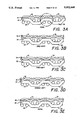
- FIG. 8a illustrates a cross machine section of the fabric of FIG. 7, taken along the line 8a--8a in FIG. 7 and FIB. 8b illustrates a cross machine section of the fabric of FIG. 7, taken along the line of 8b--8b in FIG. 7.
- the present invention is a papermakers' forming fabric particularly useful for, but not restricted to, the formation of brown paper.
- the fabric has a high fiber support, uniform drainage paths, high permeability, high stretch resistance, good abrasion resistance, and can be produced at a cost that makes it economical as a brown paper forming fabric.
- the fabric of the present invention is a self-stitched construction including two essentially distinct fabric layers, one on top of the other.
- the top layer that will form the papermaking surface incorporates relatively fine yarns in both the machine direction and the cross machine direction, which, in the preferred embodiment, are woven in a 2 ⁇ 2 weave pattern.
- the bottom fabric layer that will contact the machine elements incorporates relatively coarse yarns in the machine direction and the cross machine direction, also preferably in a 2 ⁇ 2 weave pattern.
- This fabric is essentially a hybrid double-layer structure in that each layer contains its own system of machine direction yarns and cross machine direction yarns. The only discontinuity in either layer occurs when selected cross machine direction yarns from the top fabric layer dive down and engage selected machine direction yarns from the bottom fabric layer to create the composite structure by binding the two layers together. No additional binding thread is necessary.
- the required ideal seating condition and ideal self-stitching condition are described with reference to the drawing below.
- the machine direction yarns and the cross machine direction yarns used in the present invention are preferably synthetic yarns of materials conventionally used in such fabrics, such as polyamides (Nylon), polyesters (Dacron), and acrylic fibers (Orlon, Dynel and Acrilan), or co-polymers (Saran).
- the machine direction yarns and the cross machine direction yarns may be in the form of monofilament, multifilament or staple yarns or plied or wrapped yarns.
- the specific physical properties of the selected yarns, for example, modulus, elongation, free shrink and thermal shrink can be chosen to optimize the geometry configuration of the final fabric product.
- the diameter of the yarns employed in the fabric for the present invention is determined by the position in the fabric structure.
- the machine direction yarns and the cross machine direction yarns in the top fabric layer are approximately equal in diameter and approximately half the size of the machine direction yarns and the cross machine direction yarns in the bottom fabric layer, those yarns also being approximately equal in diameter.
- the top fabric layer incorporates yarns that are 0.16 millimeter (machine direction) by 0.18 millimeter (cross machine direction) and the bottom fabric layer incorporates yarns that are 0.34 millimeter (machine direction) by 0.36 millimeter (cross machine direction).
- the size of the yarns in both systems can be increased or decreased to suit the individual requirements of a particular application for the papermaking fabric.
- the weave pattern used in the preferred embodiment of the fabric of the present invention is a twill weave characterized by a diagonal line on the face of the fabric.
- Both the top fabric layer and the bottom fabric layer are 2 ⁇ 2 twill, meaning that the machine direction yarns go over two cross machine direction yarns and under two cross machine direction yarns in a repeating pattern.
- the twills in the mating fabrics will have a reverse orientation relative to each other, that is the upper surface of the top fabric layer is a right to left twill while the upper surface of the bottom fabric layer is a left to right twill or vice versa.
- the top fabric layer and the bottom fabric layer must be positioned relative to each other such that the relationship between the lower surface machine direction floats of the top fabric layer interface with the upper surface cross machine direction floats of the bottom fabric layer in a maximum contact same plane, essentially 90 degree cross shaped orientation mode, which provides ideal interface symmetry.
- FIG. 1a illustrates the upper papermaking surface of the top fabric layer
- FIG. 1b is a machine direction section (taken along line 1b--1b in FIG. 1a)
- FIG. 1c is a cross machine direction section (taken along line 1c--1c in FIG. 1a), respectively, of the top fabric layer of one embodiment of the present invention.
- the top fabric layer 10 includes relatively fine machine direction 12 and cross machine direction 14 yarns interwoven in a 2 ⁇ 2 twill weave pattern.
- the floats of cross machine direction yarn 14 can be seen across the papermaking surface view. Consistent with the 2 ⁇ 2 twill weave, these floats ascend from right to left across the fabric 10, constituting a right to left twill.
- FIGS. 2a illustrates the upper interfacing surface of the bottom layer fabric
- FIG. 2b illustrates machine direction section (taken along the line 2b--2b in FIG. 2a)
- FIGS. 2c and 2d illustrate cross machine direction sections (taken along the lines 2c--2c and 2d--2d in FIG. 2a), respectively, of the bottom fabric layer used in one embodiment of the fabric of the present invention.
- the bottom fabric layer 20 includes relatively coarse machine direction 22 and cross machine direction 24 yarns interwoven in a 2 ⁇ 2 twill pattern. The floats of cross machine direction yarn 24 can be seen across the interfacing surface view in FIG. 2a.
- FIGS. 3a-3e illustrates the possible and the ideal seating arrangements between the top fabric layer 10 and the bottom fabric layer 20 at the stacked or overlying cross machine direction yarns.
- the top fabric layer machine direction yarns 12 and the bottom fabric layer machine direction yarns 22 are unstacked, that is each bottom fabric layer machine direction yarn 22 is intermediately spaced between a pair of top fabric machine direction yarns 12.
- the non-stitching cross machine direction yarns 14 of the top fabric layer and the cross machine direction yarns 24 of the bottom fabric layer are stacked. That is, the bottom fabric layer cross machine direction yarn 24 is directly under the top fabric layer cross machine direction yarn 14. This is illustrated in FIG. 3a and FIG. 3e.
- FIGS. 3a-3e show positions of only a non-stitching cross machine direction yarn of the top fabric layer relative to a cross machine direction yarn of the bottom fabric layer. This distinction is further explained by comparing FIGS. 3a-3e to FIGS. 6b and 6c.
- the top fabric layer 10 can then be positioned relative to the bottom fabric 20 in four locals, labeled Ideal, One-Left, Two-Left, Three-Left, and Ideal again respectively. It should also be noted that only in the ideal position are the top fabric layer 10 and the bottom fabric layer 20 oriented such that both lower surface machine direction floats of the top fabric layer 10 interface with the upper surface cross machine direction floats of the bottom fabric layer in the prescribed maximum contact same plane, essentially 90 degree, cross shaped orientation mode, as shown in FIG. 5 and described below.
- FIG. 4 illustrates the relationship between the papermaking surface of the top fabric layer 10 and the interfacing surface of the bottom fabric layer 20 where the above-described seating arrangement has been achieved.
- the self-stitching points used in the composite fabric structure of one embodiment of the present invention have been marked with a "o” and labeled "S".
- more or less self-stitching points could be utilized, provided they meet the ideal location criteria, depending upon the overall papermaking and structural requirements of the final composite forming fabric product.
- FIG. 5 illustrates the relationship between the lower surface imprint of the top fabric layer 10 and the upper surface imprint of the bottom fabric layer 20 utilized in one embodiment of the present invention.
- the mating of these respective imprints indicate the areas where the yarns of the two fabric layers interface.
- the lower machine direction floats 12 of the top fabric layer 10 contact the upper cross machine direction floats 24 of the bottom fabric layer 20 in a maximum contact same plane, essentially 90 degree cross shaped orientation mode, the cross shape being shown in FIG. 5; this ideal interface area is circled in FIGS. 3a and 6b.
- a typical ideal self-stitching point "S" where the fine cross machine direction yarn 14 of the top fabric layer 10 can most easily dip down, specifically dip further down from its already down position, to engage the machine direction yarn 22 of the bottom fabric layer 20 at its highest most accessible point is indicated by the "S" label.
- both the ideal seating arrangement and the ideal self-stitching points are representative typical positions which occur frequently within a pattern repeat. In a properly designed composite fabric, all the interfacing areas should satisfy the ideal seating arrangement criteria. However, the number of ideal self-stitching points "S" actually utilized within a pattern repeat will depend upon the ultimate objectives for the product.
- FIG. 6a illustrates the combined structure, specifically the relationship between the sheet making upper surface of the top fabric layer 10, and interfacing upper surface of the bottom fabric layer 20 of the preferred embodiment of the present invention where the above-described ideal seating arrangement has been achieved.
- the ideal in the composite fabric structure of one embodiment of the present invention have been marked with an "o" and labeled "S".
- FIG. 6b, taken along line 6b-6b in FIG. 6a, and FIG. 6c, taken along line 6c-6c in FIG. 6a illustrate two cross machine direction sections and FIG. 6d, taken along line 6d-6d in FIG. 6a, and FIG. 6e, taken along line 6e-6e in FIG. 6a, illustrate two machine direction sections of the preferred embodiment of the present invention.
- FIGS. 6b and 6c illustrate the paths of the two distinct cross machine direction yarns the non-stitching yarn in the former and the stitching yarn in the latter, and clearly show the role and positioning of these alternating cross machine direction yarns in this fabric.
- the typical ideal seating arrangement previously described is apparent in the cross machine direction section in FIG. 6b where there is a stacked relationship between the cross machine direction yarns 14 of the top fabric layer 10 and the cross machine direction yarns 24 of the bottom fabric layer 20.
- FIG. 6c no bottom fabric layer 20 cross machine direction yarn 24 below the fabric layer 10 cross machine direction yarn 14 which in this case is a stitching yarn as are all alternating top fabric layer 10 cross machine direction yarns 14.
- the typical ideal self-stitching point marked "S" is apparent in FIG.
- the self-stitching is done by each self-stitching top fabric layer cross machine direction yarn 14 on every eighth bottom fabric layer machine direction yarn 22 so that, with the alternating nature of the stitching pattern, every machine direction yarn 22 in the bottom fabric layer 20 is eventually interlaced with every other cross machine direction yarn 14 from the top fabric layer 10 within the confines of one pattern repeat.
- the self-stitch provided by every other fine cross machine direction yarn 14 from the top fabric layer 10 is merely an extension from its already down or under float position which allows it to descend somewhat further down to interlace with the machine direction yarn 22 in the bottom fabric layer 20 which is at that point in its highest position.
- the machine direction yarn 22 in the bottom fabric 20 is optimally accessible.
- the elevation of representative machine direction yarns relative to each other in a weave repeat is shown in FIG. 2D. As can be seen in that figure, a possible stitch point occurs when the machine direction yarn is at a highest elevation compared to the other machine direction yarns in the weave repeat.
- FIG. 7 illustrates the combined structure with the papermaking surface of the top fabric layer 10 overlaid on the interfacing surface of the bottom fabric layer 20 and the self-stitch points marked with an "o" and labeled "S".
- a typical ideal seating arrangement will produce a situation where the lower floats of the machine direction yarns 12 in the top fabric layer 10 interface with the upper float of the cross machine direction yarn 24 in the bottom fabric layer 20 in the required 90 degree cross-shaped orientation mode, as shown within the circled area.
- This ideal seating arrangement condition occurs numerous times within a pattern repeat of the present invention.
- the ideal self-stitching points, marked "o” and labeled "S” typically, also occur quite frequently within a pattern repeat.
- the utilized frequency of these ideal self-stitching points which exist along every other fine cross machine direction yarn 14 in the top fabric layer 10 is once every sixteen machine direction yarns 12 in the top fabric layer 10 and once every eight machine direction yarns 22 in the bottom fabric layer 20.
- the net result is that at some point along every machine direction yarn 22 in the bottom fabric layer 20 an interlace is achieved with the top fabric layer 10 within a pattern repeat.
- This self-stitching frequency can be increased or decreased, always using the ideal self-stitching points only, depending upon the particular application for the final product.
- FIGS. 8a and 8b illustrate the two configurations, non-stitching and stitching for the cross machine direction yarns 14 of the top fabric layer 10 as they relate to the bottom fabric layer 20 in the preferred embodiment of the present invention.
- FIG. 8a illustrates the cross machine direction yarns 14 of the composite fabric taken along line 8a--8a in FIG. 7 at the stacked, non-stitching position
- FIG. 8b taken along line 8b--8b in FIG. 7, shows the intermediately spaced self-stitching yarns cross machine direction yarn 14 of the top fabric layer 10.
- the typical ideal seating arrangement is circled and the typical self-stitching point is marked "o" and labeled "S".
Abstract
Description
Claims (15)
Priority Applications (5)
| Application Number | Priority Date | Filing Date | Title |
|---|---|---|---|
| US07/309,785 US5052448A (en) | 1989-02-10 | 1989-02-10 | Self stitching multilayer papermaking fabric |
| CA000612064A CA1327742C (en) | 1989-02-10 | 1989-09-20 | Papermaking fabric |
| AU49085/90A AU626631B2 (en) | 1989-02-10 | 1990-02-05 | Papermaking fabric |
| JP2031288A JP2563842B2 (en) | 1989-02-10 | 1990-02-09 | Fabric for papermaking |
| US08/129,674 USRE35777E (en) | 1989-02-10 | 1993-09-30 | Self stitching multilayer papermaking fabric |
Applications Claiming Priority (1)
| Application Number | Priority Date | Filing Date | Title |
|---|---|---|---|
| US07/309,785 US5052448A (en) | 1989-02-10 | 1989-02-10 | Self stitching multilayer papermaking fabric |
Related Child Applications (1)
| Application Number | Title | Priority Date | Filing Date |
|---|---|---|---|
| US08/129,674 Reissue USRE35777E (en) | 1989-02-10 | 1993-09-30 | Self stitching multilayer papermaking fabric |
Publications (1)
| Publication Number | Publication Date |
|---|---|
| US5052448A true US5052448A (en) | 1991-10-01 |
Family
ID=23199671
Family Applications (2)
| Application Number | Title | Priority Date | Filing Date |
|---|---|---|---|
| US07/309,785 Ceased US5052448A (en) | 1989-02-10 | 1989-02-10 | Self stitching multilayer papermaking fabric |
| US08/129,674 Expired - Lifetime USRE35777E (en) | 1989-02-10 | 1993-09-30 | Self stitching multilayer papermaking fabric |
Family Applications After (1)
| Application Number | Title | Priority Date | Filing Date |
|---|---|---|---|
| US08/129,674 Expired - Lifetime USRE35777E (en) | 1989-02-10 | 1993-09-30 | Self stitching multilayer papermaking fabric |
Country Status (4)
| Country | Link |
|---|---|
| US (2) | US5052448A (en) |
| JP (1) | JP2563842B2 (en) |
| AU (1) | AU626631B2 (en) |
| CA (1) | CA1327742C (en) |
Cited By (24)
| Publication number | Priority date | Publication date | Assignee | Title |
|---|---|---|---|---|
| US5112685A (en) * | 1991-02-11 | 1992-05-12 | Hoechst Celanese Corporation | Dryer screen made from poly(2-methyl-1,5-pentylene) terephthalamide |
| US5130155A (en) * | 1989-05-10 | 1992-07-14 | Masato Yamate | Processed raw egg preservable at room temperature and process therefor |
| US5454405A (en) * | 1994-06-02 | 1995-10-03 | Albany International Corp. | Triple layer papermaking fabric including top and bottom weft yarns interwoven with a warp yarn system |
| US5482567A (en) * | 1994-12-06 | 1996-01-09 | Huyck Licensco, Inc. | Multilayer forming fabric |
| US5520225A (en) * | 1995-01-23 | 1996-05-28 | Wangner Systems Corp. | Pocket arrangement in the support surface of a woven papermaking fabric |
| AT1726U1 (en) * | 1996-09-18 | 1997-10-27 | Tiroler Loden Gmbh | FABRICS AND METHOD FOR THE PRODUCTION THEREOF |
| EP0834609A1 (en) * | 1996-09-18 | 1998-04-08 | Tiroler Loden GmbH | Fabric for the manufacture of a garment and process for the manufacture of this fabric |
| EP0889160A1 (en) * | 1997-07-02 | 1999-01-07 | Andreas Kufferath GmbH & Co. KG | Screencloth for papermaking machine |
| US5954097A (en) * | 1996-08-14 | 1999-09-21 | The Procter & Gamble Company | Papermaking fabric having bilaterally alternating tie yarns |
| US6148869A (en) * | 1998-12-17 | 2000-11-21 | Wangner Systems Corporation | Dual layer papermaking fabric formed in a balanced weave |
| WO2000076622A1 (en) * | 1999-06-16 | 2000-12-21 | Tamfelt Oyj Abp | Filter cloth and replaceable filter module |
| US6202705B1 (en) | 1998-05-23 | 2001-03-20 | Astenjohnson, Inc. | Warp-tied composite forming fabric |
| US6227256B1 (en) | 1999-12-13 | 2001-05-08 | Albany International Corp. | Multi-layer papermaking fabric having long weft floats on its support and machine surfaces |
| US6581645B1 (en) | 1999-06-29 | 2003-06-24 | Astenjohnson, Inc. | Warp-tied composite forming fabric |
| US20060112999A1 (en) * | 2004-11-26 | 2006-06-01 | Nippon Filcon Co., Ltd. | Industrial two-layer fabric |
| US20060169346A1 (en) * | 2005-02-01 | 2006-08-03 | Ernest Fahrer | Multiple contour binders in triple layer fabrics |
| US20060278295A1 (en) * | 2005-05-19 | 2006-12-14 | Nippon Filcon Co. | Industrial two-layer fabric |
| US20070151617A1 (en) * | 2005-12-29 | 2007-07-05 | Ernest Fahrer | Different contour paired binders in multi-layer fabrics |
| EP2584091A1 (en) | 2011-10-22 | 2013-04-24 | Heimbach GmbH & Co. KG | Woven papermaker fabric, in particular a forming fabric |
| EP2899311A1 (en) | 2014-01-28 | 2015-07-29 | Heimbach GmbH & Co. KG | Paper maker fabric |
| WO2017161511A1 (en) * | 2016-03-23 | 2017-09-28 | 许长云 | Weft self-binding forming fabric |
| US20180245247A1 (en) * | 2015-08-25 | 2018-08-30 | Nitta Corporation | Textile machine belt |
| EP3384085A4 (en) * | 2015-12-04 | 2019-11-27 | Valmet Technologies Oy | Paper machine fabric |
| US20220195642A1 (en) * | 2020-12-23 | 2022-06-23 | Valmet Technologies Oy | Industrial Textile |
Families Citing this family (26)
| Publication number | Priority date | Publication date | Assignee | Title |
|---|---|---|---|---|
| US5983953A (en) | 1994-09-16 | 1999-11-16 | Weavexx Corporation | Paper forming progess |
| US5967195A (en) | 1997-08-01 | 1999-10-19 | Weavexx Corporation | Multi-layer forming fabric with stitching yarn pairs integrated into papermaking surface |
| ATE211191T1 (en) | 1998-11-18 | 2002-01-15 | Heimbach Gmbh Thomas Josef | TEXTILE SURFACE STRUCTURE |
| US6179013B1 (en) | 1999-10-21 | 2001-01-30 | Weavexx Corporation | Low caliper multi-layer forming fabrics with machine side cross machine direction yarns having a flattened cross section |
| US6585006B1 (en) | 2000-02-10 | 2003-07-01 | Weavexx Corporation | Papermaker's forming fabric with companion yarns |
| US6244306B1 (en) | 2000-05-26 | 2001-06-12 | Weavexx Corporation | Papermaker's forming fabric |
| US6253796B1 (en) | 2000-07-28 | 2001-07-03 | Weavexx Corporation | Papermaker's forming fabric |
| US6745797B2 (en) | 2001-06-21 | 2004-06-08 | Weavexx Corporation | Papermaker's forming fabric |
| US6860969B2 (en) | 2003-01-30 | 2005-03-01 | Weavexx Corporation | Papermaker's forming fabric |
| US6837277B2 (en) | 2003-01-30 | 2005-01-04 | Weavexx Corporation | Papermaker's forming fabric |
| US7059357B2 (en) | 2003-03-19 | 2006-06-13 | Weavexx Corporation | Warp-stitched multilayer papermaker's fabrics |
| US6896009B2 (en) * | 2003-03-19 | 2005-05-24 | Weavexx Corporation | Machine direction yarn stitched triple layer papermaker's forming fabrics |
| US7243687B2 (en) * | 2004-06-07 | 2007-07-17 | Weavexx Corporation | Papermaker's forming fabric with twice as many bottom MD yarns as top MD yarns |
| DE102004044572A1 (en) * | 2004-09-15 | 2006-03-30 | Voith Fabrics Patent Gmbh | Paper machine clothing |
| US7195040B2 (en) * | 2005-02-18 | 2007-03-27 | Weavexx Corporation | Papermaker's forming fabric with machine direction stitching yarns that form machine side knuckles |
| US7484538B2 (en) * | 2005-09-22 | 2009-02-03 | Weavexx Corporation | Papermaker's triple layer forming fabric with non-uniform top CMD floats |
| US7219701B2 (en) * | 2005-09-27 | 2007-05-22 | Weavexx Corporation | Papermaker's forming fabric with machine direction stitching yarns that form machine side knuckles |
| US7275566B2 (en) | 2006-02-27 | 2007-10-02 | Weavexx Corporation | Warped stitched papermaker's forming fabric with fewer effective top MD yarns than bottom MD yarns |
| US7580229B2 (en) | 2006-04-27 | 2009-08-25 | Hitachi Global Storage Technologies Netherlands B.V. | Current-perpendicular-to-the-plane (CPP) magnetoresistive sensor with antiparallel-free layer structure and low current-induced noise |
| US7487805B2 (en) * | 2007-01-31 | 2009-02-10 | Weavexx Corporation | Papermaker's forming fabric with cross-direction yarn stitching and ratio of top machined direction yarns to bottom machine direction yarns of less than 1 |
| US7624766B2 (en) * | 2007-03-16 | 2009-12-01 | Weavexx Corporation | Warped stitched papermaker's forming fabric |
| US20090183795A1 (en) * | 2008-01-23 | 2009-07-23 | Kevin John Ward | Multi-Layer Papermaker's Forming Fabric With Long Machine Side MD Floats |
| US8304586B2 (en) * | 2010-02-02 | 2012-11-06 | Celanese International Corporation | Process for purifying ethanol |
| US7766053B2 (en) * | 2008-10-31 | 2010-08-03 | Weavexx Corporation | Multi-layer papermaker's forming fabric with alternating paired and single top CMD yarns |
| US8251103B2 (en) * | 2009-11-04 | 2012-08-28 | Weavexx Corporation | Papermaker's forming fabric with engineered drainage channels |
| US8344186B2 (en) * | 2010-02-02 | 2013-01-01 | Celanese International Corporation | Processes for producing ethanol from acetaldehyde |
Citations (5)
| Publication number | Priority date | Publication date | Assignee | Title |
|---|---|---|---|---|
| DE3224236A1 (en) * | 1982-06-29 | 1984-03-08 | Hermann Wangner Gmbh & Co Kg, 7410 Reutlingen | Composite fabric as a covering for the sheet-forming region of a paper machine |
| DE3329740A1 (en) * | 1983-08-17 | 1985-03-07 | Hermann Wangner Gmbh & Co Kg, 7410 Reutlingen | COVERING FOR PAPER MACHINES |
| US4554953A (en) * | 1983-02-18 | 1985-11-26 | Hermann Wangner Gmbh & Co. | Composite fabric for use as clothing for the sheet forming section of a papermaking machine |
| US4564051A (en) * | 1983-07-16 | 1986-01-14 | Andreas Kufferath Gmbh & Co. Kg | Multiple ply dewatering screen particularly for a web forming part of a paper making machine |
| US4945952A (en) * | 1987-02-19 | 1990-08-07 | F. Oberdorfer Gmbh & Co. Kg Industriegewebe-Technik | Multiple layer paper making wire with zig zag directed connecting threads between layers |
Family Cites Families (59)
| Publication number | Priority date | Publication date | Assignee | Title |
|---|---|---|---|---|
| US3127308A (en) * | 1964-03-31 | Dual wire dewatering apparatus | ||
| US173677A (en) * | 1876-02-15 | Improvement in fabrics | ||
| US636482A (en) * | 1897-04-12 | 1899-11-07 | William L Barrell | Drier-felt for paper-machines. |
| US1983352A (en) * | 1930-05-16 | 1934-12-04 | New England Fibre Blanket Comp | Printer's blanket and method of making |
| US1879243A (en) * | 1931-06-05 | 1932-09-27 | Mount Vernonwoodberry Mills In | Fabric |
| US1994280A (en) * | 1932-04-21 | 1935-03-12 | Hindle Thomas | Drier felt for use on paper making machines |
| US2047542A (en) * | 1933-02-13 | 1936-07-14 | William A Barrell | Drier felt for paper machines and the like |
| US1991366A (en) * | 1933-02-13 | 1935-02-19 | William A Barrell | Asbestos faced drier felt |
| DE731243C (en) * | 1934-10-26 | 1943-02-04 | Geraer Filztuchfabrik Lechla & | Drying felt |
| GB451752A (en) * | 1936-01-01 | 1936-08-11 | Thomas Hardman And Sons Ltd | An improved felt for use in the manufacture of paper, cardboard and analogous materials |
| US2157082A (en) * | 1937-04-16 | 1939-05-02 | Ayers Ltd | Felt |
| US2180054A (en) * | 1937-08-23 | 1939-11-14 | Hindle Thomas | Paper maker's drier felt |
| US2713193A (en) * | 1950-01-14 | 1955-07-19 | Bates Mfg Co | Textile fabrics and methods for producing the fabrics |
| US2742059A (en) * | 1951-02-22 | 1956-04-17 | J H Fenner & Co Holdings Ltd | Multiple-ply textile fabrics |
| US2949134A (en) * | 1955-09-23 | 1960-08-16 | Scapa Dryers Ltd | Papermakers' felts and like industrial woven textile fabrics |
| US2936796A (en) * | 1956-07-03 | 1960-05-17 | Scapa Dryers Ltd | Paper-makers' dryer felt |
| US2934097A (en) * | 1956-12-06 | 1960-04-26 | Hindle Thomas | Papermakers' dryer felts |
| US2862283A (en) * | 1957-05-28 | 1958-12-02 | Russell Mfg Co | Anti-friction fabric |
| US3222246A (en) * | 1961-12-14 | 1965-12-07 | Huyck Corp | Backup wire for fourdrinier machine |
| US3207659A (en) * | 1963-01-22 | 1965-09-21 | Huyck Corp | Method of making papermaker's fabric and the finished fabric |
| US3214329A (en) * | 1963-01-24 | 1965-10-26 | Huyck Corp | Fabric press improvements |
| SE307728B (en) * | 1963-03-20 | 1969-01-13 | Schullstroem & Sjoestroems Fab | |
| US3214326A (en) * | 1963-04-16 | 1965-10-26 | Huyck Corp | Paper pressing method, felt and apparatus |
| US3325909A (en) * | 1966-01-27 | 1967-06-20 | Huyck Corp | Fabric for pumping fluids |
| US3573164A (en) * | 1967-08-22 | 1971-03-30 | Procter & Gamble | Fabrics with improved web transfer characteristics |
| US3885603A (en) * | 1973-11-21 | 1975-05-27 | Creech Evans S | Papermaking fabric |
| US3885602A (en) * | 1973-11-21 | 1975-05-27 | Creech Evans S | Woven fourdrinier fabric |
| SE385486B (en) * | 1974-10-10 | 1976-07-05 | Nordiska Maskinfilt Ab | PROPAGATION WIRE FOR PAPER, CELLULOSE OR SIMILAR MACHINES AND MANUFACTURED THE SAME |
| US4289173A (en) * | 1975-10-30 | 1981-09-15 | Scapa-Porritt Limited | Papermakers fabrics |
| US4141388A (en) * | 1977-03-23 | 1979-02-27 | Albany International Corporation | Paper machine dryer fabric |
| US4186780A (en) * | 1978-12-15 | 1980-02-05 | Albany International Corp. | Seam construction for multi-layer felts |
| US4359069A (en) * | 1980-08-28 | 1982-11-16 | Albany International Corp. | Low density multilayer papermaking fabric |
| DE3036409C2 (en) * | 1980-09-26 | 1983-01-20 | Hermann Wangner Gmbh & Co Kg, 7410 Reutlingen | Double-layer screen for the screen part of a paper machine |
| US4403632A (en) * | 1981-03-19 | 1983-09-13 | Albany International Corp. | Corrugator belt with high air permeability |
| US4361618A (en) * | 1981-05-18 | 1982-11-30 | Ascoe Felts, Inc. | Papermakers felt with improved drainage |
| SE430425C (en) * | 1981-06-23 | 1986-09-19 | Nordiskafilt Ab | PREPARATION WIRES FOR PAPER, CELLULOSA OR SIMILAR MACHINES |
| DE3146385C2 (en) * | 1981-11-23 | 1985-10-31 | Hermann Wangner Gmbh & Co Kg, 7410 Reutlingen | Double-layer fabric as a covering for paper machines |
| DE3224187C2 (en) * | 1982-06-29 | 1989-01-12 | Hermann Wangner Gmbh & Co Kg, 7410 Reutlingen | Bandage fabric as a covering for the sheet forming area of a paper machine |
| DE3301810C2 (en) * | 1983-01-20 | 1986-01-09 | Hermann Wangner Gmbh & Co Kg, 7410 Reutlingen | Composite fabric as a covering for the sheet forming part of a paper machine |
| SE435739B (en) * | 1983-02-23 | 1984-10-15 | Nordiskafilt Ab | DOUBLE TEXTILE TYPE FORMATION WIRES |
| DE3329739C1 (en) * | 1983-08-17 | 1985-01-10 | Hermann Wangner Gmbh & Co Kg, 7410 Reutlingen | Multi-layer covering for paper machines |
| KR930006052B1 (en) * | 1984-03-15 | 1993-07-03 | 미쯔비시 지도샤 고교 가부시끼가이샤 | Device for controlling engine and method thereof |
| DE3426264A1 (en) * | 1984-07-17 | 1986-01-30 | Franz F. 5160 Düren Kufferath | DRAINAGE TAPE FOR PRESSES IN THE WET OF A PAPER MACHINE |
| US4642261A (en) * | 1984-12-21 | 1987-02-10 | Unaform Inc. | Papermakers fabric having a tight bottom weft geometry |
| JPS61275493A (en) * | 1985-05-30 | 1986-12-05 | 日本フイルコン株式会社 | Double fabric for papermaking |
| JPS6297994A (en) * | 1985-10-21 | 1987-05-07 | 日本フイルコン株式会社 | Double fabric for papermaking |
| JPS62162091A (en) * | 1986-01-09 | 1987-07-17 | 日本フイルコン株式会社 | Papermaking double fabric |
| US4709732A (en) * | 1986-05-13 | 1987-12-01 | Huyck Corporation | Fourteen harness dual layer weave |
| DE3627775A1 (en) * | 1986-08-16 | 1988-02-18 | Demetron | METHOD FOR PRODUCING TARGETS |
| DE3634134A1 (en) * | 1986-10-07 | 1988-04-21 | Wangner Gmbh Co Kg Hermann | COVER FOR THE SHEET FORMING PART OF A PAPER MACHINE |
| US4759975A (en) * | 1986-11-06 | 1988-07-26 | Asten Group, Inc. | Papermaker's wet press felt having multi-layered base fabric |
| CA1277209C (en) * | 1986-11-28 | 1990-12-04 | Dale B. Johnson | Composite forming fabric |
| JPS63145496A (en) * | 1986-12-02 | 1988-06-17 | 日本フイルコン株式会社 | Papermaking multilayer fabric |
| US4705601A (en) * | 1987-02-05 | 1987-11-10 | B.I. Industries, Inc. | Multi-ply paper forming fabric with ovate warp yarns in lowermost ply |
| US4759976A (en) * | 1987-04-30 | 1988-07-26 | Albany International Corp. | Forming fabric structure to resist rewet of the paper sheet |
| AU623102B2 (en) * | 1987-10-07 | 1992-05-07 | Tamfelt, Inc. | Papermaker press felt |
| US4921750A (en) * | 1988-05-25 | 1990-05-01 | Asten Group, Inc. | Papermaker's thru-dryer embossing fabric |
| FI81624C (en) * | 1988-12-08 | 1990-11-12 | Tamfelt Oy Ab | PAPPERSMASKINDUK. |
| US5013330A (en) * | 1989-12-04 | 1991-05-07 | Asten Group, Inc. | Multi-layered papermakers fabric for thru-dryer application |
-
1989
- 1989-02-10 US US07/309,785 patent/US5052448A/en not_active Ceased
- 1989-09-20 CA CA000612064A patent/CA1327742C/en not_active Expired - Fee Related
-
1990
- 1990-02-05 AU AU49085/90A patent/AU626631B2/en not_active Ceased
- 1990-02-09 JP JP2031288A patent/JP2563842B2/en not_active Expired - Fee Related
-
1993
- 1993-09-30 US US08/129,674 patent/USRE35777E/en not_active Expired - Lifetime
Patent Citations (5)
| Publication number | Priority date | Publication date | Assignee | Title |
|---|---|---|---|---|
| DE3224236A1 (en) * | 1982-06-29 | 1984-03-08 | Hermann Wangner Gmbh & Co Kg, 7410 Reutlingen | Composite fabric as a covering for the sheet-forming region of a paper machine |
| US4554953A (en) * | 1983-02-18 | 1985-11-26 | Hermann Wangner Gmbh & Co. | Composite fabric for use as clothing for the sheet forming section of a papermaking machine |
| US4564051A (en) * | 1983-07-16 | 1986-01-14 | Andreas Kufferath Gmbh & Co. Kg | Multiple ply dewatering screen particularly for a web forming part of a paper making machine |
| DE3329740A1 (en) * | 1983-08-17 | 1985-03-07 | Hermann Wangner Gmbh & Co Kg, 7410 Reutlingen | COVERING FOR PAPER MACHINES |
| US4945952A (en) * | 1987-02-19 | 1990-08-07 | F. Oberdorfer Gmbh & Co. Kg Industriegewebe-Technik | Multiple layer paper making wire with zig zag directed connecting threads between layers |
Cited By (38)
| Publication number | Priority date | Publication date | Assignee | Title |
|---|---|---|---|---|
| US5130155A (en) * | 1989-05-10 | 1992-07-14 | Masato Yamate | Processed raw egg preservable at room temperature and process therefor |
| US5112685A (en) * | 1991-02-11 | 1992-05-12 | Hoechst Celanese Corporation | Dryer screen made from poly(2-methyl-1,5-pentylene) terephthalamide |
| US5454405A (en) * | 1994-06-02 | 1995-10-03 | Albany International Corp. | Triple layer papermaking fabric including top and bottom weft yarns interwoven with a warp yarn system |
| CN1066793C (en) * | 1994-08-23 | 2001-06-06 | 阿尔巴尼国际公司 | Triple layer papermaking fabric providing improved fiber support |
| US5482567A (en) * | 1994-12-06 | 1996-01-09 | Huyck Licensco, Inc. | Multilayer forming fabric |
| US5520225A (en) * | 1995-01-23 | 1996-05-28 | Wangner Systems Corp. | Pocket arrangement in the support surface of a woven papermaking fabric |
| US5954097A (en) * | 1996-08-14 | 1999-09-21 | The Procter & Gamble Company | Papermaking fabric having bilaterally alternating tie yarns |
| AT1726U1 (en) * | 1996-09-18 | 1997-10-27 | Tiroler Loden Gmbh | FABRICS AND METHOD FOR THE PRODUCTION THEREOF |
| EP0834609A1 (en) * | 1996-09-18 | 1998-04-08 | Tiroler Loden GmbH | Fabric for the manufacture of a garment and process for the manufacture of this fabric |
| AT404142B (en) * | 1996-09-18 | 1998-08-25 | Tiroler Loden Gmbh | FABRIC FOR PRODUCING CLOTHING AND METHOD FOR PRODUCING SUCH A FABRIC |
| US6110850A (en) * | 1996-09-18 | 2000-08-29 | Tiroler Loden Gmbh | Fabric |
| EP0889160A1 (en) * | 1997-07-02 | 1999-01-07 | Andreas Kufferath GmbH & Co. KG | Screencloth for papermaking machine |
| US6202705B1 (en) | 1998-05-23 | 2001-03-20 | Astenjohnson, Inc. | Warp-tied composite forming fabric |
| US6148869A (en) * | 1998-12-17 | 2000-11-21 | Wangner Systems Corporation | Dual layer papermaking fabric formed in a balanced weave |
| WO2000076622A1 (en) * | 1999-06-16 | 2000-12-21 | Tamfelt Oyj Abp | Filter cloth and replaceable filter module |
| US6581645B1 (en) | 1999-06-29 | 2003-06-24 | Astenjohnson, Inc. | Warp-tied composite forming fabric |
| US6227256B1 (en) | 1999-12-13 | 2001-05-08 | Albany International Corp. | Multi-layer papermaking fabric having long weft floats on its support and machine surfaces |
| US20060112999A1 (en) * | 2004-11-26 | 2006-06-01 | Nippon Filcon Co., Ltd. | Industrial two-layer fabric |
| US7412991B2 (en) * | 2004-11-26 | 2008-08-19 | Nippon Filcon Co., Ltd. | Industrial two-layer fabric |
| US20060169346A1 (en) * | 2005-02-01 | 2006-08-03 | Ernest Fahrer | Multiple contour binders in triple layer fabrics |
| US7124781B2 (en) * | 2005-02-01 | 2006-10-24 | Albany International Corp. | Multiple contour binders in triple layer fabrics |
| US20060278295A1 (en) * | 2005-05-19 | 2006-12-14 | Nippon Filcon Co. | Industrial two-layer fabric |
| US7426943B2 (en) * | 2005-05-19 | 2008-09-23 | Nippon Filcon Co., Ltd. | Industrial two-layer fabric |
| US20070151617A1 (en) * | 2005-12-29 | 2007-07-05 | Ernest Fahrer | Different contour paired binders in multi-layer fabrics |
| US7357155B2 (en) * | 2005-12-29 | 2008-04-15 | Albany International Corp. | Different contour paired binders in multi-layer fabrics |
| EP2584091A1 (en) | 2011-10-22 | 2013-04-24 | Heimbach GmbH & Co. KG | Woven papermaker fabric, in particular a forming fabric |
| US20130098497A1 (en) * | 2011-10-22 | 2013-04-25 | Heimbach Gmbh & Co. Kg | Woven papermaker fabric, in particular a forming fabric |
| US8640741B2 (en) * | 2011-10-22 | 2014-02-04 | Heimbach Gmbh & Co. Kg | Woven papermaker fabric, in particular a forming fabric |
| EP2899311A1 (en) | 2014-01-28 | 2015-07-29 | Heimbach GmbH & Co. KG | Paper maker fabric |
| US9745696B2 (en) | 2014-01-28 | 2017-08-29 | Heimbach Gmbh & Co. Kg | Paper maker fabric |
| US20180245247A1 (en) * | 2015-08-25 | 2018-08-30 | Nitta Corporation | Textile machine belt |
| US10557218B2 (en) * | 2015-08-25 | 2020-02-11 | Nitta Corporation | Textile machine belt |
| EP3384085A4 (en) * | 2015-12-04 | 2019-11-27 | Valmet Technologies Oy | Paper machine fabric |
| WO2017161511A1 (en) * | 2016-03-23 | 2017-09-28 | 许长云 | Weft self-binding forming fabric |
| US20220195642A1 (en) * | 2020-12-23 | 2022-06-23 | Valmet Technologies Oy | Industrial Textile |
| CN114657674A (en) * | 2020-12-23 | 2022-06-24 | 维美德技术有限公司 | Industrial textile |
| EP4019696A1 (en) * | 2020-12-23 | 2022-06-29 | Valmet Technologies, Inc. | Industrial textile |
| US11629438B2 (en) * | 2020-12-23 | 2023-04-18 | Valmet Technologies, Inc. | Industrial textile |
Also Published As
| Publication number | Publication date |
|---|---|
| JP2563842B2 (en) | 1996-12-18 |
| USRE35777E (en) | 1998-04-28 |
| AU626631B2 (en) | 1992-08-06 |
| JPH02269891A (en) | 1990-11-05 |
| AU4908590A (en) | 1990-08-16 |
| CA1327742C (en) | 1994-03-15 |
Similar Documents
| Publication | Publication Date | Title |
|---|---|---|
| US5052448A (en) | Self stitching multilayer papermaking fabric | |
| US4709732A (en) | Fourteen harness dual layer weave | |
| JP2896805B2 (en) | Forming fabric with intervening cross-machine directional yarn | |
| CA2177778C (en) | Sixteen harness multi-layer forming fabric | |
| US5025839A (en) | Two-ply papermakers forming fabric with zig-zagging MD yarns | |
| CA2528015C (en) | Industrial two-layer fabric | |
| US5641001A (en) | Papermaker's fabric with additional cross machine direction yarns positioned in saddles | |
| FI80091B (en) | FLERSKIKTIG PAPPERSMASKINSVIRA. | |
| CA1225570A (en) | Fabric for use as cloth for papermaking machines | |
| KR960007934A (en) | Triple layered paper fabric with improved fibrous support | |
| US5829489A (en) | Two-layer paper-making fabric having auxiliary weft on the paper-making side | |
| ZA200504164B (en) | Multi-layer fabric for paper making machines | |
| MXPA06006552A (en) | Double layer woven fabric for industrial use. | |
| JP2004534159A (en) | Industrial fabric including yarn assembly | |
| WO1999053135A1 (en) | Multilayer papermaking fabric | |
| US4789009A (en) | Sixteen harness dual layer weave | |
| US5601120A (en) | Pin seam with double end loops and method | |
| CA2759355C (en) | Industrial two-layer fabric | |
| FI87667B (en) | BEKLAEDNAD FOER EN ARKFORMNINGSDEL VID EN PAPPERSMASKIN | |
| JP2013501153A (en) | Forming fabric for manufacturing fibrous web materials | |
| AU2003300929A1 (en) | Multi-layer fabric for paper making machine | |
| CA2352898A1 (en) | Warp triplet forming fabrics with optional weft binder yarns | |
| MXPA00000825A (en) | Warp-tied composite forming fabric | |
| KR20070006817A (en) | Dryer fabric seam |
Legal Events
| Date | Code | Title | Description |
|---|---|---|---|
| AS | Assignment |
Owner name: HUYCK CORPORATION, NORTH CAROLINA Free format text: ASSIGNMENT OF ASSIGNORS INTEREST.;ASSIGNOR:GIVIN, WILLIAM R.;REEL/FRAME:005048/0601 Effective date: 19890222 |
|
| STCF | Information on status: patent grant |
Free format text: PATENTED CASE |
|
| AS | Assignment |
Owner name: HUYCK LICENSCO, INC., A DELAWARE CORPORATION, DELA Free format text: ASSIGNMENT OF ASSIGNORS INTEREST.;ASSIGNOR:HUYCK CORPORATION, A DE CORP.;REEL/FRAME:006080/0885 Effective date: 19920330 |
|
| RF | Reissue application filed |
Effective date: 19930930 |
|
| RR | Request for reexamination filed |
Effective date: 19940307 |
|
| FPAY | Fee payment |
Year of fee payment: 4 |
|
| FEPP | Fee payment procedure |
Free format text: PAYOR NUMBER ASSIGNED (ORIGINAL EVENT CODE: ASPN); ENTITY STATUS OF PATENT OWNER: LARGE ENTITY |
|
| AS | Assignment |
Owner name: WEAVEXX CORPORATION, NORTH CAROLINA Free format text: ASSIGNMENT OF ASSIGNORS INTEREST;ASSIGNOR:HUYCK LICENSCO, INC.;REEL/FRAME:008478/0787 Effective date: 19970424 |
|
| FEPP | Fee payment procedure |
Free format text: PAYOR NUMBER ASSIGNED (ORIGINAL EVENT CODE: ASPN); ENTITY STATUS OF PATENT OWNER: LARGE ENTITY Free format text: PAYER NUMBER DE-ASSIGNED (ORIGINAL EVENT CODE: RMPN); ENTITY STATUS OF PATENT OWNER: LARGE ENTITY |
|
| AS | Assignment |
Owner name: CIBC WORLD MARKETS PLC, UNITED KINGDOM Free format text: SECURITY AGREEMENT;ASSIGNORS:ZERIUM SA;WEAVEXX CORPORATION;STOWE WOODWARD LICENSCO LLC;AND OTHERS;REEL/FRAME:013791/0539 Effective date: 20030225 |
|
| AS | Assignment |
Owner name: XERIUM S.A., MASSACHUSETTS Free format text: RELEASE BY SECURED PARTY;ASSIGNOR:CIBC WORLD MARKETS PLC;REEL/FRAME:026732/0743 Effective date: 20050519 Owner name: STOWE WOODWARD LICENSCO LLC, MASSACHUSETTS Free format text: RELEASE BY SECURED PARTY;ASSIGNOR:CIBC WORLD MARKETS PLC;REEL/FRAME:026732/0743 Effective date: 20050519 Owner name: WEAVEXX CORPORATION, MASSACHUSETTS Free format text: RELEASE BY SECURED PARTY;ASSIGNOR:CIBC WORLD MARKETS PLC;REEL/FRAME:026732/0743 Effective date: 20050519 Owner name: HUYCK LICENSCO INC., MASSACHUSETTS Free format text: RELEASE BY SECURED PARTY;ASSIGNOR:CIBC WORLD MARKETS PLC;REEL/FRAME:026732/0743 Effective date: 20050519 Owner name: STOWE WOODWARD LLC, MASSACHUSETTS Free format text: RELEASE BY SECURED PARTY;ASSIGNOR:CIBC WORLD MARKETS PLC;REEL/FRAME:026732/0743 Effective date: 20050519 |
|
| AS | Assignment |
Owner name: JEFFERIES FINANCE LLC, NEW YORK Free format text: GRANT OF SECURITY INTEREST;ASSIGNOR:WEAVEXX, LLC;REEL/FRAME:030427/0555 Effective date: 20130517 Owner name: PNC BANK NATIONAL ASSOCIATION, PENNSYLVANIA Free format text: GRANT OF SECURITY INTEREST;ASSIGNOR:WEAVEXX, LLC;REEL/FRAME:030427/0542 Effective date: 20130517 |
|
| AS | Assignment |
Owner name: WEAVEXX, LLC, NORTH CAROLINA Free format text: RELEASE BY SECURED PARTY;ASSIGNOR:PNC BANK, NATIONAL ASSOCIATION, AS COLLATERAL AGENT;REEL/FRAME:037044/0059 Effective date: 20151103 |
|
| AS | Assignment |
Owner name: WEAVEXX, LLC, NORTH CAROLINA Free format text: RELEASE BY SECURED PARTY;ASSIGNOR:JEFFERIES FINANCE LLC;REEL/FRAME:039637/0771 Effective date: 20160809 |