US5052390A - Method and apparatus for defibrillating the heart using internal esophageal electrode and external chest electrode - Google Patents
Method and apparatus for defibrillating the heart using internal esophageal electrode and external chest electrode Download PDFInfo
- Publication number
- US5052390A US5052390A US07/214,778 US21477888A US5052390A US 5052390 A US5052390 A US 5052390A US 21477888 A US21477888 A US 21477888A US 5052390 A US5052390 A US 5052390A
- Authority
- US
- United States
- Prior art keywords
- patient
- electrode
- heart
- defibrillation
- joules
- Prior art date
- Legal status (The legal status is an assumption and is not a legal conclusion. Google has not performed a legal analysis and makes no representation as to the accuracy of the status listed.)
- Expired - Lifetime
Links
Images


Classifications
-
- A—HUMAN NECESSITIES
- A61—MEDICAL OR VETERINARY SCIENCE; HYGIENE
- A61N—ELECTROTHERAPY; MAGNETOTHERAPY; RADIATION THERAPY; ULTRASOUND THERAPY
- A61N1/00—Electrotherapy; Circuits therefor
- A61N1/02—Details
- A61N1/04—Electrodes
- A61N1/05—Electrodes for implantation or insertion into the body, e.g. heart electrode
- A61N1/0517—Esophageal electrodes
-
- A—HUMAN NECESSITIES
- A61—MEDICAL OR VETERINARY SCIENCE; HYGIENE
- A61N—ELECTROTHERAPY; MAGNETOTHERAPY; RADIATION THERAPY; ULTRASOUND THERAPY
- A61N1/00—Electrotherapy; Circuits therefor
- A61N1/18—Applying electric currents by contact electrodes
- A61N1/32—Applying electric currents by contact electrodes alternating or intermittent currents
- A61N1/38—Applying electric currents by contact electrodes alternating or intermittent currents for producing shock effects
- A61N1/39—Heart defibrillators
- A61N1/3904—External heart defibrillators [EHD]
-
- A—HUMAN NECESSITIES
- A61—MEDICAL OR VETERINARY SCIENCE; HYGIENE
- A61N—ELECTROTHERAPY; MAGNETOTHERAPY; RADIATION THERAPY; ULTRASOUND THERAPY
- A61N1/00—Electrotherapy; Circuits therefor
- A61N1/18—Applying electric currents by contact electrodes
- A61N1/32—Applying electric currents by contact electrodes alternating or intermittent currents
- A61N1/38—Applying electric currents by contact electrodes alternating or intermittent currents for producing shock effects
- A61N1/39—Heart defibrillators
- A61N1/395—Heart defibrillators for treating atrial fibrillation
Definitions
- This invention relates to a method of defibrillating the heart.
- Heart fibrillation There are two types of heart fibrillation, namely, ventricular and atrial fibrillation.
- ventricular fibrillation When a person's heart is in ventricular fibrillation, death is imminent. In ventricular fibrillation, the heart cells that stimulate the heart muscles are not coordinated so that although they stimulate the muscles, they produce rapid, erratic excitation without coordinated contraction of the ventricle. There is no effective simultaneous action to cause the heart to beat in rhythmic fashion. To avoid death, immediate defibrillation is essential.
- Atrial fibrillation When a person's heart is in atrial fibrillation, the atria are uncoordinated and are not beating in a rhythmic fashion. Atrial fibrillation generally is not life threatening. Atrial fibrillation with a clinically stable patient may be resolved with drug therapy, and when necessary, with electrical fibrillation. If atrial defibrillation is coupled with rapid ventricular response and other medical problems, it may be necessary to perform emergency electrical defibrillation.
- Defibrillation is achieved by delivering to the heart cells enough voltage to override the erratic voltages in the fibrillating heart so that they can rearrange themselves with order. That action is called "repolarization". In this "repolarized" condition no heart action of any kind occurs for a period of three to eight seconds. After this three to eight seconds period, the heart cells arrange themselves to either fibrillate again or start a coordinated effort to beat in rhythm. If they fibrillate again, it is necessary to defibrillate them again, usually with more power. It may be necessary to do this several times before the heart cells arrange themselves to coordinate and beat in rhythm.
- Defibrillation by high power is the accepted procedure today. Heavy duty equipment is required to deliver a very severe electric shock to the patient.
- the shock is delivered by placing two large paddle-type electrodes, each about three inches in diameter, at selected locations on the chest. By pressing down hard on the electrodes to make good electrical contact with the skin, and by pressing a button provided on one of the paddle electrodes, the system is triggered so as to deliver the shock.
- the electrical shock is very abrupt; several thousand volts are impressed across the electrodes in a few milliseconds. In accordance with this procedure, in theory if the patient is given a large enough shock, some of it will pass though the heart and achieve repolarization.
- the power required for this type of defibrillation is a minimum of 100 joules; sometimes 200 joules are required, and usually 360 joules are necessary.
- the need is to use the smallest amount of power to the patient to accomplish defibrillation as it is the least abusive to the patient.
- the emphasis has been placed on electrical wave shape to achieve efficiency and thereby reduce the power necessary for defibrillation.
- two small intimately located electrodes are used.
- one electrode is located in the lower esophagus intimate to the posterior section of the heart and the other small electrode is placed on the chest approximately on a line between the two nipples and part way between the sternum and the left nipple.
- one electrode is located in the lower esophagus intimate to the posterior section of the heart and the other small electrode is placed on the chest approximately over the apex of the left ventricle.
- the placement of the electrodes provides a precise electrical path through the heart as selected by the location of the chest electrode, depending on whether atrial or ventricular defibrillation is required.
- the power required is at a minimum of 30 to 70 joules, usually at the 50 joule level. This is equivalent to the power commonly used for internal defibrillation.
- the internal electrode in the esophagus may be inserted through the mouth in the fashion of a gastric tube.
- the electrode itself may be of selected stiffness and flexibility so that it can be inserted directly into the esophagus.
- the electrode carries a plurality of circular contacts provided in the surface of the lower end of the tube.
- a stop may be carried on the other end of the electrode which will engage the face of the patient so as to prevent further electrode insertion when the distal end is in the proper location.
- a stop may be carried on the other end of the electrode which will engage the nares of the patent so as to prevent further electrode insertion when the distal end is in the proper location.
- the external electrode may be an adhesively attached electrode as is commonly used for EKG, etc.
- the defibrillation unit may be reduced in size.
- the reduction in size may be quite remarkable because the components in most defibrillators--the large capacitor, the batteries to charge the capacitor, the rectifiers to recharge the batteries, and the relay to discharge the capacitor to the electrodes, are all heavy duty electrical equipment. By reducing the power needed, these may be reduced in size and weight and may be of solid state electronic components instead of electrical components.
- the size and weight of the defibrillator unit may be reduced to 1/4 to 1/3 the size and weight of the units now used to deliver 30-360 joules.
- FIG. 1 is a somewhat diagrammatic view, of the head and chest of a patient and showing the use of the present invention
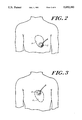
- FIGS. 2 and 3 are plan views of a patient and showing the preferred precise placement of the external electrode on the chest to perform ventricular and atrial defibrillation, respectively;
- FIG. 4 is a perspective view of the two electrodes used to perform defibrillation in accordance with the present invention.
- FIG. 5 is an enlarged perspective view of the distal end of the internal electrode shown in FIG. 4;
- FIG. 6 is a box diagram of the electrical circuit connected to the electrode to supply the defibrillating pulse.
- FIG. 1 depicts a patient being assisted by the defibrillating system of the present invention.
- a first electrode 10 is shown disposed in the patient's esophagus 11, and an external electrode 12 is shown placed on the patient's chest.
- the electrodes are connected to an electrical circuit 16 shown in FIG. 6 which impresses a pulse across the electrodes 10 and 12 so as to instantaneously direct current through the heart.
- the electrode 10 is shown to include a curved, tubular body 18 which is shaped to be inserted directly into the patient's esophagus without the aid of a larger tubular member serving as a guide for that purpose. It is to be understood, however, that the system of the present invention may be used in combination with other apparatus, and it is contemplated that the electrode 10 in certain situations may be guided into the esophagus through a previously inserted tube such as a gastric tube.
- the electrode 10 carries a stop 20 at its proximal end 22 which may be used to limit the depth of penetration of the electrode 10 into the esophagus.
- the stop 20 should not cover the mouth or otherwise interfere with the passage of air to and from the lungs.
- the body of the electrode 10 preferably is somewhat flexible, in the nature of a commercially available gastric tube, so that it may be inserted in the esophagus and will not injure the esophageal lining. It may or may not call for the use of lubricant. Moreover, the electrode may be inserted through the mouth or nose.
- the electrode may be identical to that shown in U.S. Pat. No. 4,574,807 dated Mar. 11, 1988 and entitled “Method and Apparatus for Pacing the Heart Employing Internal and External Electrodes". The present applicant is a coinventor in that patent. The electrode is also shown in applicant's U.S. Pat. No. 4,683,890 dated Aug. 4, 1987 and entitled "Method and Apparatus for Controlled Breathing Employing Internal and External Electrodes".
- the distal end 30 of the electrode 10 is shown in detail. It includes four contact rings 24A-24D embedded in its surface. While four rings are shown, a lesser or greater number may be used.
- the contact rings in the embodiment shown are formed from a continuous length of tinned copper wire 26.
- the wire 26 extends inside the body 18 to first ring contact 24A, in turn formed by several turns of wire, on the surface of the body 18.
- the wire again enters the body 18 beyond the contact 24A and reemerges at the next ring contact 24B, also formed by several additional turns of wire.
- the third and fourth ring contacts 24C and 24D are similarly formed and connected to one another by the wire inside the body.
- the four electrode contacts are connected in series and formed from a single length of wire.
- each of the ring contacts may be 0.2-inch in axial length, and they may be spaced one inch apart.
- the wire may typically be 24-gauge
- the distal end 30 of the body is provided with a smooth, rounded tip 31 which will slide smoothly down the esophagus or guide tube (if used).
- the distal end 30 is positioned so that the several ring contacts 24 lie in the lower third of the esophagus intimate to the posterior section of the heart H.
- the stop 20 insures proper positioning of the electrode.
- the external electrode 12 may be like those used in electrocardiogram machines. As shown in FIG. 4, the electrode includes a flat, circular pad 32. A conducting gelatin is applied to the pad 32 when used to make good electrical contact with the patient's skin. The under surface of the pad 32 may also carry an adhesive to secure the electrode in place on the patient's chest.
- the electrodes are shown connected to a defibrillator 36 which represents any one of the many units now commercially available and capable of rendering a variable discharge. For use as part of the present invention, it must be capable of producing energy outputs (shock) in the 30-70 joules range.
- the unit may, of course, include a variety of display scopes, meters and recorders for indicating heart rate, electrocardiograph, available energy, energy selectors, etc.
- the unit shown has a capacitor 60, battery 62, wave shaper 64, switch controlled relay 66 and output control dial 68 for providing the energy output for defibrillation. Assuming the battery 62 is sufficiently charged, it will charge the capacitor 60 which in turn may be discharged by the switch controlled relay 66.
- the switch controlling the relay may be carried by external electrode 12. The battery may in turn be charged from a 110 volt source through the charger 70.
- the several contact rings 24 on the internal electrode 10 are each capable of defining the electrical path to the externally applied electrode 12 so that the current of limited value will flow between them and through the heart.
- the contact ring 24 on the internal electrode which defines the path of least resistance with the electrode 12 placed on the chest will complete the electrical circuit.
- FIGS. 2 and 3 the precise location for the placement of the external electrode is suggested for both atrial and ventricular defibrillation.
- FIG. 3 which shows the placement of the external electrode for atrial defibrillation
- electrode 12 is on a line between the nipples N of the patient, part way between the sternum and the left nipple.
- FIG. 2 the external electrode 12 is shown placed above the apex of the left ventrical. With that placement, the electrical path between the inner and outer electrodes passes directly through the left ventrical.
- the minimum electrical resistance encountered enables minimum energy to be used as an instantaneous discharge from presently available units.
- the present invention permits the use of available defibrillators capable of reducing the energy discharge to 30-100 joules, it invites the manufacture and use of smaller and much less expensive defibrillators than those now available having ranges from 30-360 joules.
Abstract
Description
Claims (8)
Priority Applications (4)
| Application Number | Priority Date | Filing Date | Title |
|---|---|---|---|
| US07/214,778 US5052390A (en) | 1988-07-05 | 1988-07-05 | Method and apparatus for defibrillating the heart using internal esophageal electrode and external chest electrode |
| GB8825414A GB2220356A (en) | 1988-07-05 | 1988-10-31 | Defibrillating the heart using internal esophageal electrode and external chest electrode |
| DE3838025A DE3838025A1 (en) | 1988-07-05 | 1988-11-09 | METHOD AND DEVICE FOR DEFIBRILLING THE HEART USING AN INTERNAL EEAR EAR ELECTRODE AND AN EXTERNAL CHEST ELECTRODE |
| JP63308689A JPH01303161A (en) | 1987-07-05 | 1988-12-06 | Method and apparatus for defibrillation of heart using in vivo esophagus electrode and in vitro breast electrode |
Applications Claiming Priority (1)
| Application Number | Priority Date | Filing Date | Title |
|---|---|---|---|
| US07/214,778 US5052390A (en) | 1988-07-05 | 1988-07-05 | Method and apparatus for defibrillating the heart using internal esophageal electrode and external chest electrode |
Publications (1)
| Publication Number | Publication Date |
|---|---|
| US5052390A true US5052390A (en) | 1991-10-01 |
Family
ID=22800393
Family Applications (1)
| Application Number | Title | Priority Date | Filing Date |
|---|---|---|---|
| US07/214,778 Expired - Lifetime US5052390A (en) | 1987-07-05 | 1988-07-05 | Method and apparatus for defibrillating the heart using internal esophageal electrode and external chest electrode |
Country Status (4)
| Country | Link |
|---|---|
| US (1) | US5052390A (en) |
| JP (1) | JPH01303161A (en) |
| DE (1) | DE3838025A1 (en) |
| GB (1) | GB2220356A (en) |
Cited By (28)
| Publication number | Priority date | Publication date | Assignee | Title |
|---|---|---|---|---|
| US5191885A (en) * | 1989-02-06 | 1993-03-09 | Arczo Medical Electronics, Inc. | Method of terminating an arrhythmia |
| US5343860A (en) * | 1989-02-06 | 1994-09-06 | Arzco Medical Systems, Inc. | Esophageal recording/pacing catheter with thermistor and cardiac imaging transceiver |
| US5394880A (en) * | 1994-03-17 | 1995-03-07 | Atlee, Iii; John L. | Esophageal stethoscope |
| US5715816A (en) * | 1993-12-06 | 1998-02-10 | Sensor Devices, Inc. | Oximeter probes and methods for the invasive use thereof |
| US5743261A (en) * | 1993-12-06 | 1998-04-28 | Sensor Devices, Inc. | Methods and apparatus for the invasive use of oximeter probes |
| US5904711A (en) * | 1996-02-08 | 1999-05-18 | Heartport, Inc. | Expandable thoracoscopic defibrillation catheter system and method |
| US6449507B1 (en) | 1996-04-30 | 2002-09-10 | Medtronic, Inc. | Method and system for nerve stimulation prior to and during a medical procedure |
| US6487446B1 (en) | 2000-09-26 | 2002-11-26 | Medtronic, Inc. | Method and system for spinal cord stimulation prior to and during a medical procedure |
| US6532388B1 (en) | 1996-04-30 | 2003-03-11 | Medtronic, Inc. | Method and system for endotracheal/esophageal stimulation prior to and during a medical procedure |
| US20030074039A1 (en) * | 1999-06-25 | 2003-04-17 | Puskas John D. | Devices and methods for vagus nerve stimulation |
| US6628987B1 (en) | 2000-09-26 | 2003-09-30 | Medtronic, Inc. | Method and system for sensing cardiac contractions during vagal stimulation-induced cardiopalegia |
| US20040186531A1 (en) * | 1996-04-30 | 2004-09-23 | Jahns Scott E. | Method and system for nerve stimulation and cardiac sensing prior to and during a medical procedure |
| WO2006097923A1 (en) * | 2005-03-16 | 2006-09-21 | Hadasit Medical Research Services And Development Company Ltd. | A defibrillation system and method for generating a predetermined voltage pulse for defibrillation |
| US7142910B2 (en) | 1997-08-26 | 2006-11-28 | Emory University | Methods of indirectly stimulating the vagus nerve with an electrical field |
| US7269457B2 (en) | 1996-04-30 | 2007-09-11 | Medtronic, Inc. | Method and system for vagal nerve stimulation with multi-site cardiac pacing |
| US20100004708A1 (en) * | 1996-04-30 | 2010-01-07 | Medtronic, Inc. | Method and system for nerve stimulation and cardiac sensing prior to and during a medical procedure |
| US8406868B2 (en) | 2010-04-29 | 2013-03-26 | Medtronic, Inc. | Therapy using perturbation and effect of physiological systems |
| US8620425B2 (en) | 2010-04-29 | 2013-12-31 | Medtronic, Inc. | Nerve signal differentiation in cardiac therapy |
| US8639327B2 (en) | 2010-04-29 | 2014-01-28 | Medtronic, Inc. | Nerve signal differentiation in cardiac therapy |
| US8706223B2 (en) | 2011-01-19 | 2014-04-22 | Medtronic, Inc. | Preventative vagal stimulation |
| US8718763B2 (en) | 2011-01-19 | 2014-05-06 | Medtronic, Inc. | Vagal stimulation |
| US8725259B2 (en) | 2011-01-19 | 2014-05-13 | Medtronic, Inc. | Vagal stimulation |
| US8781582B2 (en) | 2011-01-19 | 2014-07-15 | Medtronic, Inc. | Vagal stimulation |
| US8781583B2 (en) | 2011-01-19 | 2014-07-15 | Medtronic, Inc. | Vagal stimulation |
| US9636512B2 (en) * | 2014-11-05 | 2017-05-02 | Medtronic, Inc. | Implantable cardioverter-defibrillator (ICD) system having multiple common polarity extravascular defibrillation electrodes |
| WO2017151576A1 (en) * | 2016-02-29 | 2017-09-08 | The Methodist Hospital System | System and method using cardiac-esophageal impedance mapping to predict and detect esophageal injury during cardiac ablation procedures |
| US10736773B2 (en) | 2013-03-13 | 2020-08-11 | Advanced Cooling Therapy, Inc. | Devices, systems, and methods for managing patient temperature and correcting cardiac arrhythmia |
| US11553963B2 (en) | 2021-03-09 | 2023-01-17 | Circle Safe | Phrenic nerve stimulation |
Families Citing this family (1)
| Publication number | Priority date | Publication date | Assignee | Title |
|---|---|---|---|---|
| NL2001698C2 (en) * | 2008-06-18 | 2009-12-22 | Nasophlex B V | Cardioverter / defibrillator. |
Citations (4)
| Publication number | Priority date | Publication date | Assignee | Title |
|---|---|---|---|---|
| US4198963A (en) * | 1978-10-19 | 1980-04-22 | Michigan Instruments, Inc. | Cardiopulmonary resuscitator, defibrillator and monitor |
| US4574807A (en) * | 1984-03-02 | 1986-03-11 | Carl Hewson | Method and apparatus for pacing the heart employing external and internal electrodes |
| US4640298A (en) * | 1980-06-03 | 1987-02-03 | Peter Pless | Esophageal electrode probe useful for electrical stimulation of the heart |
| US4706688A (en) * | 1981-05-18 | 1987-11-17 | Don Michael T Anthony | Non-invasive cardiac device |
Family Cites Families (4)
| Publication number | Priority date | Publication date | Assignee | Title |
|---|---|---|---|---|
| US4088138A (en) * | 1974-01-02 | 1978-05-09 | Cardiac Resuscitator Corp. | Cardiac resuscitator and monitoring apparatus |
| US4351330A (en) * | 1978-01-30 | 1982-09-28 | Scarberry Eugene N | Emergency internal defibrillation |
| JPS6135871A (en) * | 1984-07-27 | 1986-02-20 | Matsui Denki Kogyo Kk | Spray foaming apparatus |
| US4735206A (en) * | 1986-07-28 | 1988-04-05 | Brunswick Manufacturing Co., Inc. | Method and apparatus for defibrillating and pacing the heart |
-
1988
- 1988-07-05 US US07/214,778 patent/US5052390A/en not_active Expired - Lifetime
- 1988-10-31 GB GB8825414A patent/GB2220356A/en not_active Withdrawn
- 1988-11-09 DE DE3838025A patent/DE3838025A1/en not_active Withdrawn
- 1988-12-06 JP JP63308689A patent/JPH01303161A/en active Pending
Patent Citations (4)
| Publication number | Priority date | Publication date | Assignee | Title |
|---|---|---|---|---|
| US4198963A (en) * | 1978-10-19 | 1980-04-22 | Michigan Instruments, Inc. | Cardiopulmonary resuscitator, defibrillator and monitor |
| US4640298A (en) * | 1980-06-03 | 1987-02-03 | Peter Pless | Esophageal electrode probe useful for electrical stimulation of the heart |
| US4706688A (en) * | 1981-05-18 | 1987-11-17 | Don Michael T Anthony | Non-invasive cardiac device |
| US4574807A (en) * | 1984-03-02 | 1986-03-11 | Carl Hewson | Method and apparatus for pacing the heart employing external and internal electrodes |
Cited By (44)
| Publication number | Priority date | Publication date | Assignee | Title |
|---|---|---|---|---|
| US5191885A (en) * | 1989-02-06 | 1993-03-09 | Arczo Medical Electronics, Inc. | Method of terminating an arrhythmia |
| US5343860A (en) * | 1989-02-06 | 1994-09-06 | Arzco Medical Systems, Inc. | Esophageal recording/pacing catheter with thermistor and cardiac imaging transceiver |
| US5715816A (en) * | 1993-12-06 | 1998-02-10 | Sensor Devices, Inc. | Oximeter probes and methods for the invasive use thereof |
| US5743261A (en) * | 1993-12-06 | 1998-04-28 | Sensor Devices, Inc. | Methods and apparatus for the invasive use of oximeter probes |
| US5394880A (en) * | 1994-03-17 | 1995-03-07 | Atlee, Iii; John L. | Esophageal stethoscope |
| US5904711A (en) * | 1996-02-08 | 1999-05-18 | Heartport, Inc. | Expandable thoracoscopic defibrillation catheter system and method |
| US20100004708A1 (en) * | 1996-04-30 | 2010-01-07 | Medtronic, Inc. | Method and system for nerve stimulation and cardiac sensing prior to and during a medical procedure |
| US7184829B2 (en) | 1996-04-30 | 2007-02-27 | Medtronic, Inc. | Method and system for nerve stimulation prior to and during a medical procedure |
| US6532388B1 (en) | 1996-04-30 | 2003-03-11 | Medtronic, Inc. | Method and system for endotracheal/esophageal stimulation prior to and during a medical procedure |
| US8036741B2 (en) | 1996-04-30 | 2011-10-11 | Medtronic, Inc. | Method and system for nerve stimulation and cardiac sensing prior to and during a medical procedure |
| US6449507B1 (en) | 1996-04-30 | 2002-09-10 | Medtronic, Inc. | Method and system for nerve stimulation prior to and during a medical procedure |
| US20040186531A1 (en) * | 1996-04-30 | 2004-09-23 | Jahns Scott E. | Method and system for nerve stimulation and cardiac sensing prior to and during a medical procedure |
| US7269457B2 (en) | 1996-04-30 | 2007-09-11 | Medtronic, Inc. | Method and system for vagal nerve stimulation with multi-site cardiac pacing |
| US7225019B2 (en) | 1996-04-30 | 2007-05-29 | Medtronic, Inc. | Method and system for nerve stimulation and cardiac sensing prior to and during a medical procedure |
| US7142910B2 (en) | 1997-08-26 | 2006-11-28 | Emory University | Methods of indirectly stimulating the vagus nerve with an electrical field |
| US7310552B2 (en) | 1997-08-26 | 2007-12-18 | Puskas John D | Apparatus for indirectly stimulating the vagus nerve with an electrical field |
| US7340299B2 (en) | 1997-08-26 | 2008-03-04 | Puskas John D | Methods of indirectly stimulating the vagus nerve to achieve controlled asystole |
| US7072720B2 (en) | 1999-06-25 | 2006-07-04 | Emory University | Devices and methods for vagus nerve stimulation |
| US7840278B1 (en) | 1999-06-25 | 2010-11-23 | Puskas John D | Devices and methods for vagus nerve stimulation |
| US20030074039A1 (en) * | 1999-06-25 | 2003-04-17 | Puskas John D. | Devices and methods for vagus nerve stimulation |
| US6487446B1 (en) | 2000-09-26 | 2002-11-26 | Medtronic, Inc. | Method and system for spinal cord stimulation prior to and during a medical procedure |
| US7184828B2 (en) | 2000-09-26 | 2007-02-27 | Medtronic, Inc. | Method and system for spinal cord stimulation prior to and during a medical procedure |
| US20070208381A1 (en) * | 2000-09-26 | 2007-09-06 | Medtronic, Inc. | Method and system for spinal cord stimulation prior to and during a medical procedure |
| US6628987B1 (en) | 2000-09-26 | 2003-09-30 | Medtronic, Inc. | Method and system for sensing cardiac contractions during vagal stimulation-induced cardiopalegia |
| WO2006097923A1 (en) * | 2005-03-16 | 2006-09-21 | Hadasit Medical Research Services And Development Company Ltd. | A defibrillation system and method for generating a predetermined voltage pulse for defibrillation |
| US8406868B2 (en) | 2010-04-29 | 2013-03-26 | Medtronic, Inc. | Therapy using perturbation and effect of physiological systems |
| US8888699B2 (en) | 2010-04-29 | 2014-11-18 | Medtronic, Inc. | Therapy using perturbation and effect of physiological systems |
| US8620425B2 (en) | 2010-04-29 | 2013-12-31 | Medtronic, Inc. | Nerve signal differentiation in cardiac therapy |
| US8639327B2 (en) | 2010-04-29 | 2014-01-28 | Medtronic, Inc. | Nerve signal differentiation in cardiac therapy |
| US11129988B2 (en) | 2010-04-29 | 2021-09-28 | Medtronic, Inc. | Nerve signal differentiation in cardiac therapy |
| US8423134B2 (en) | 2010-04-29 | 2013-04-16 | Medtronic, Inc. | Therapy using perturbation and effect of physiological systems |
| US10207112B2 (en) | 2010-04-29 | 2019-02-19 | Medtronic, Inc. | Cardiac therapy including vagal stimulation |
| US9468764B2 (en) | 2010-04-29 | 2016-10-18 | Medtronic, Inc. | Nerve signal differentiation in cardiac therapy |
| US8718763B2 (en) | 2011-01-19 | 2014-05-06 | Medtronic, Inc. | Vagal stimulation |
| US8781583B2 (en) | 2011-01-19 | 2014-07-15 | Medtronic, Inc. | Vagal stimulation |
| US9155893B2 (en) | 2011-01-19 | 2015-10-13 | Medtronic, Inc. | Use of preventative vagal stimulation in treatment of acute myocardial infarction or ischemia |
| US9211413B2 (en) | 2011-01-19 | 2015-12-15 | Medtronic, Inc. | Preventing use of vagal stimulation parameters |
| US8781582B2 (en) | 2011-01-19 | 2014-07-15 | Medtronic, Inc. | Vagal stimulation |
| US8725259B2 (en) | 2011-01-19 | 2014-05-13 | Medtronic, Inc. | Vagal stimulation |
| US8706223B2 (en) | 2011-01-19 | 2014-04-22 | Medtronic, Inc. | Preventative vagal stimulation |
| US10736773B2 (en) | 2013-03-13 | 2020-08-11 | Advanced Cooling Therapy, Inc. | Devices, systems, and methods for managing patient temperature and correcting cardiac arrhythmia |
| US9636512B2 (en) * | 2014-11-05 | 2017-05-02 | Medtronic, Inc. | Implantable cardioverter-defibrillator (ICD) system having multiple common polarity extravascular defibrillation electrodes |
| WO2017151576A1 (en) * | 2016-02-29 | 2017-09-08 | The Methodist Hospital System | System and method using cardiac-esophageal impedance mapping to predict and detect esophageal injury during cardiac ablation procedures |
| US11553963B2 (en) | 2021-03-09 | 2023-01-17 | Circle Safe | Phrenic nerve stimulation |
Also Published As
| Publication number | Publication date |
|---|---|
| GB2220356A (en) | 1990-01-10 |
| GB8825414D0 (en) | 1988-11-30 |
| JPH01303161A (en) | 1989-12-07 |
| DE3838025A1 (en) | 1990-01-11 |
Similar Documents
| Publication | Publication Date | Title |
|---|---|---|
| US5052390A (en) | Method and apparatus for defibrillating the heart using internal esophageal electrode and external chest electrode | |
| US4735206A (en) | Method and apparatus for defibrillating and pacing the heart | |
| Spickler et al. | Totally self-contained intracardiac pacemaker | |
| US3866615A (en) | Portable electronic cardiac stimulator | |
| US4683890A (en) | Method and apparatus for controlled breathing employing internal and external electrodes | |
| US3738370A (en) | Method of defibrillating a malfunctioning heart by means of electrodes located within the atrium | |
| US5324323A (en) | Multiple channel cardiosynchronous myoplasty apparatus | |
| US5417713A (en) | Transesophageal defibrillating system | |
| US5314451A (en) | Replaceable battery for implantable medical device | |
| US7463924B2 (en) | Methods for determining placement of an implantable cardiac stimulus device | |
| US4821723A (en) | Biphasic waveforms for defibrillation | |
| US4481953A (en) | Endocardial lead having helically wound ribbon electrode | |
| US11083904B2 (en) | Bisphasic or multiphasic pulse waveform and method | |
| US3693627A (en) | Stimulator for treatment of tachycardia with a burst of stimuli having a continuously variable rate | |
| JP2004508149A (en) | Subcutaneously implantable defibrillator and optional pacemaker | |
| Fisher et al. | Comparative effectiveness of pacing techniques for termination of well‐tolerated sustained ventricular tachycardia | |
| US6751501B1 (en) | Method and apparatus for myocardial control | |
| US5383908A (en) | Defibrillation system having innominate vein electrode and method for its use | |
| US20050038474A1 (en) | Implantable automatic defibrillator with subcutaneous electrodes | |
| US20050038476A1 (en) | Coating/covering materials for the enhancement of defibrillation thresholds of implantable defibrillators/leads | |
| EP1592479B1 (en) | Tachy lead system for septal placement | |
| US6181967B1 (en) | Atrial defibrillator apparatus and method of use | |
| Troup | Early development of defibrillation devices | |
| Hickman et al. | A portable miniature transistorized radio-frequency coupled cardiac pacemaker | |
| WO2004080530A2 (en) | Specific method for implantable cardiac control |
Legal Events
| Date | Code | Title | Description |
|---|---|---|---|
| AS | Assignment |
Owner name: BRUNSWICK MANUFACTURING CO., INC., 6 THACHER LANE, Free format text: ASSIGNMENT OF ASSIGNORS INTEREST.;ASSIGNOR:HEWSON, CARL E.;REEL/FRAME:004958/0842 Effective date: 19880929 Owner name: BRUNSWICK MANUFACTURING CO., INC., A CORP. OF MA,M Free format text: ASSIGNMENT OF ASSIGNORS INTEREST;ASSIGNOR:HEWSON, CARL E.;REEL/FRAME:004958/0842 Effective date: 19880929 |
|
| AS | Assignment |
Owner name: BRUNSWICK BIOMEDICAL TECHNOLOGIES, INC., A MA CORP Free format text: ASSIGNMENT OF ASSIGNORS INTEREST.;ASSIGNOR:BRUNSWICK MANUFACTURING CO., INC.;REEL/FRAME:005426/0389 Effective date: 19900703 |
|
| STCF | Information on status: patent grant |
Free format text: PATENTED CASE |
|
| FEPP | Fee payment procedure |
Free format text: PAYOR NUMBER ASSIGNED (ORIGINAL EVENT CODE: ASPN); ENTITY STATUS OF PATENT OWNER: SMALL ENTITY |
|
| FPAY | Fee payment |
Year of fee payment: 4 |
|
| FEPP | Fee payment procedure |
Free format text: PAYER NUMBER DE-ASSIGNED (ORIGINAL EVENT CODE: RMPN); ENTITY STATUS OF PATENT OWNER: SMALL ENTITY Free format text: PAYOR NUMBER ASSIGNED (ORIGINAL EVENT CODE: ASPN); ENTITY STATUS OF PATENT OWNER: SMALL ENTITY |
|
| AS | Assignment |
Owner name: INTERNATIONALE NEDERLANDEN (U.S.) CAPITAL CORPORAT Free format text: COLLATERAL ASSIGNMENT AND SECURITY AGREEMENT (PATE;ASSIGNOR:BRUNSWICK BIOMEDICAL CORPORATION;REEL/FRAME:007894/0004 Effective date: 19960415 |
|
| FEPP | Fee payment procedure |
Free format text: PAT HOLDER CLAIMS SMALL ENTITY STATUS - SMALL BUSINESS (ORIGINAL EVENT CODE: SM02); ENTITY STATUS OF PATENT OWNER: SMALL ENTITY |
|
| FPAY | Fee payment |
Year of fee payment: 8 |
|
| REMI | Maintenance fee reminder mailed | ||
| FPAY | Fee payment |
Year of fee payment: 12 |
|
| SULP | Surcharge for late payment |
Year of fee payment: 11 |