US5050593A - Respirator triggering mechanism - Google Patents
Respirator triggering mechanism Download PDFInfo
- Publication number
- US5050593A US5050593A US07/531,949 US53194990A US5050593A US 5050593 A US5050593 A US 5050593A US 53194990 A US53194990 A US 53194990A US 5050593 A US5050593 A US 5050593A
- Authority
- US
- United States
- Prior art keywords
- valve
- expiratory
- patient
- respirator
- inspiratory
- Prior art date
- Legal status (The legal status is an assumption and is not a legal conclusion. Google has not performed a legal analysis and makes no representation as to the accuracy of the status listed.)
- Expired - Fee Related
Links
Images


Classifications
-
- A—HUMAN NECESSITIES
- A61—MEDICAL OR VETERINARY SCIENCE; HYGIENE
- A61M—DEVICES FOR INTRODUCING MEDIA INTO, OR ONTO, THE BODY; DEVICES FOR TRANSDUCING BODY MEDIA OR FOR TAKING MEDIA FROM THE BODY; DEVICES FOR PRODUCING OR ENDING SLEEP OR STUPOR
- A61M16/00—Devices for influencing the respiratory system of patients by gas treatment, e.g. mouth-to-mouth respiration; Tracheal tubes
- A61M16/20—Valves specially adapted to medical respiratory devices
-
- A—HUMAN NECESSITIES
- A61—MEDICAL OR VETERINARY SCIENCE; HYGIENE
- A61M—DEVICES FOR INTRODUCING MEDIA INTO, OR ONTO, THE BODY; DEVICES FOR TRANSDUCING BODY MEDIA OR FOR TAKING MEDIA FROM THE BODY; DEVICES FOR PRODUCING OR ENDING SLEEP OR STUPOR
- A61M16/00—Devices for influencing the respiratory system of patients by gas treatment, e.g. mouth-to-mouth respiration; Tracheal tubes
- A61M16/08—Bellows; Connecting tubes ; Water traps; Patient circuits
- A61M16/0816—Joints or connectors
- A61M16/0833—T- or Y-type connectors, e.g. Y-piece
-
- A—HUMAN NECESSITIES
- A61—MEDICAL OR VETERINARY SCIENCE; HYGIENE
- A61M—DEVICES FOR INTRODUCING MEDIA INTO, OR ONTO, THE BODY; DEVICES FOR TRANSDUCING BODY MEDIA OR FOR TAKING MEDIA FROM THE BODY; DEVICES FOR PRODUCING OR ENDING SLEEP OR STUPOR
- A61M16/00—Devices for influencing the respiratory system of patients by gas treatment, e.g. mouth-to-mouth respiration; Tracheal tubes
- A61M16/08—Bellows; Connecting tubes ; Water traps; Patient circuits
- A61M16/0816—Joints or connectors
- A61M16/0841—Joints or connectors for sampling
- A61M16/0858—Pressure sampling ports
-
- A—HUMAN NECESSITIES
- A61—MEDICAL OR VETERINARY SCIENCE; HYGIENE
- A61M—DEVICES FOR INTRODUCING MEDIA INTO, OR ONTO, THE BODY; DEVICES FOR TRANSDUCING BODY MEDIA OR FOR TAKING MEDIA FROM THE BODY; DEVICES FOR PRODUCING OR ENDING SLEEP OR STUPOR
- A61M16/00—Devices for influencing the respiratory system of patients by gas treatment, e.g. mouth-to-mouth respiration; Tracheal tubes
- A61M16/08—Bellows; Connecting tubes ; Water traps; Patient circuits
- A61M16/0866—Passive resistors therefor
-
- A—HUMAN NECESSITIES
- A61—MEDICAL OR VETERINARY SCIENCE; HYGIENE
- A61M—DEVICES FOR INTRODUCING MEDIA INTO, OR ONTO, THE BODY; DEVICES FOR TRANSDUCING BODY MEDIA OR FOR TAKING MEDIA FROM THE BODY; DEVICES FOR PRODUCING OR ENDING SLEEP OR STUPOR
- A61M16/00—Devices for influencing the respiratory system of patients by gas treatment, e.g. mouth-to-mouth respiration; Tracheal tubes
- A61M16/20—Valves specially adapted to medical respiratory devices
- A61M16/201—Controlled valves
- A61M16/206—Capsule valves, e.g. mushroom, membrane valves
-
- A—HUMAN NECESSITIES
- A61—MEDICAL OR VETERINARY SCIENCE; HYGIENE
- A61M—DEVICES FOR INTRODUCING MEDIA INTO, OR ONTO, THE BODY; DEVICES FOR TRANSDUCING BODY MEDIA OR FOR TAKING MEDIA FROM THE BODY; DEVICES FOR PRODUCING OR ENDING SLEEP OR STUPOR
- A61M16/00—Devices for influencing the respiratory system of patients by gas treatment, e.g. mouth-to-mouth respiration; Tracheal tubes
- A61M16/0003—Accessories therefor, e.g. sensors, vibrators, negative pressure
- A61M2016/0015—Accessories therefor, e.g. sensors, vibrators, negative pressure inhalation detectors
- A61M2016/0018—Accessories therefor, e.g. sensors, vibrators, negative pressure inhalation detectors electrical
- A61M2016/0024—Accessories therefor, e.g. sensors, vibrators, negative pressure inhalation detectors electrical with an on-off output signal, e.g. from a switch
-
- A—HUMAN NECESSITIES
- A61—MEDICAL OR VETERINARY SCIENCE; HYGIENE
- A61M—DEVICES FOR INTRODUCING MEDIA INTO, OR ONTO, THE BODY; DEVICES FOR TRANSDUCING BODY MEDIA OR FOR TAKING MEDIA FROM THE BODY; DEVICES FOR PRODUCING OR ENDING SLEEP OR STUPOR
- A61M39/00—Tubes, tube connectors, tube couplings, valves, access sites or the like, specially adapted for medical use
- A61M39/22—Valves or arrangement of valves
- A61M39/227—Valves actuated by a secondary fluid, e.g. hydraulically or pneumatically actuated valves
- A61M39/228—Valves actuated by a secondary fluid, e.g. hydraulically or pneumatically actuated valves with a tubular diaphragm constrictable by radial fluid force
Definitions
- This invention relates generally to triggering lung ventilating respirators and, more particularly, to a mechanism connecting a patient to a respirator for initiating the respiratory phase of the respirator.
- respirators in use today for this purpose are of the positive pressure type in which the lungs are inflated by a positive pressure supplied by the respirator during insufflation, followed by passive exhalation as the respirator pressure is removed, whereupon the lungs and chest wall recoil from their inflated positions.
- lung inflation may also be due in part to the patient's own respiratory efforts.
- the respirator acts as a mechanical assist to the patient, partially reducing the work involved and energy expended while the patient performs the breathing.
- the patient For the airway pressure to fall below threshold, the patient must evacuate, by his own active inspiratory efforts, a sizable volume from the respiratory circuit which includes the respirator tubings, connectors, passageway, humidifier and accessories which may be associated with them.
- the inspiratory effort required to trigger the respirator may become prohibitive, especially if the evacuation volume in the inspiratory circuit is relatively large compared to the capacity of their lungs. Thus, inspiratory triggering by such patients is often difficult, if at all possible.
- an inspiratory triggering device should be sensitive enough to provide the desired triggering with minimum encumbrance to the patient, and yet simple enough to be relatively light-weight, flexible, and low-cost. Furthermore, it should not adversely affect the well being of the patient or cause unnecessary inconvenience to the therapist in its operation. Such a device is presently lacking.
- an advantage of pressure triggering is that a pressure signal can be readily obtained by way of a side tap to the respiratory circuit proximal to the patient while direct attachment of the pressure transducer to the patient is not necessary.
- Its disadvantage, however, as used in current practice, is that the airway pressure that provides the trigger can be greatly attenuated in the presence of a large evacuation volume in the respiratory circuit. Apparatus that eliminates or minimizes the effect of the evaluation volume would be useful in providing sensitive pressure triggering and, hence, an object of the present invention.
- the invention resides in triggering mechanism for initiating a inspiratory phase of a respirator and includes a three-way connector which has an inspiratory conduit and an expiratory conduit. Both conduits are in communication with the respirator, as well as with a patient communicating conduit.
- a one-way valve is associated with the expiratory conduit to permit air (breath) flow only to the respirator and not from it.
- a shutter valve is associated with the inspiratory conduit to selectively permit air flow from the respirator to the patient.
- a pressure chamber surrounds and controls the operation of the inspiratory or shutter valve in response to changes in pressure in the expiratory conduit caused by a patient attempting to breathe.
- An air tap in the patient communicating conduit is connected to the respirator and when it detects a pressure change in the patient communicating tube of the three-way conduit, it triggers the respirator.
- the one-way valve in the expiratory conduit is a first closure valve and the shutter valve associated with the inspiratory conduit is a second closure valve. Together when closed, they isolate the patient from the air volume associated with the respirator and those tubes communicating with it. He is thus exposed only to the air volume of the three-way connector.
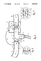
- FIG. 1 is a schematic, perspective view, partly in section, of a respirator triggering mechanism embodying the invention and shown connecting a patient to a respirator.
- FIG. 2 is a sectional view on an enlarged scale of the device shown at the time of inspiratory occlusion, when both its inspiratory and expiratory valves are in the closed positions.
- FIG. 3 is an enlarged, perspective, detailed view of the one-way or expiratory valve of the device.
- FIG. 4 is an enlarged, sectional detailed view of the expiratory valve in the open position.
- FIG. 5 is a detailed view of the shutter or inspiratory valve taken on the line V--V on FIG. 1.
- FIG. 6 is a detailed view of the inspiratory valve also taken on the line V--V but with the valve in the open position.
- FIG. 7 is an enlarged, sectional view of the inspiratory valve in the open position.
- FIG. 1 schematically shows the triggering device embodying the invention connecting a patient P to a respirator R.
- a three-way connector C has an inspiratory conduit 2 and expiratory conduit 4, each in communication with a patient connecting conduit 6 and the respirator R.
- the three-way connector may be made of polystyrene, polypropylene, polycarbonate or any other surgically acceptable material. Wherein a facial mask 8 is shown, a tracheal tube 10 alone could also be employed if conditions dictated.
- a one-way closure or expiratory valve 12 is associated with the expiratory conduit 4 to permit air (breath) flow only to the respirator, as shown by an arrow.
- a shutter or inspiratory valve generally designated 14 is associated with the inspiratory conduit 2 to selectively permit air flow from the respirator R to the patient.
- a pressure chamber 16 surrounds the inspiratory valve 14 and operates to open and close the valve in response to pressure change in the expiratory conduit 4 by the patient attempting to breathe.
- the expiratory conduit 4 is in communication with the pressure chamber 16 via a tube 18 connecting a tap 20 in the conduit to a tap 22 in the chamber.
- a side tap 24, which may also be called a pressure tap or air tap, in the patient conduit 6, is, as seen in FIGS. 1 and 2, a hollow tube in an opening in the patient conduit 6 which is connected to the respirator R by a flexible tube 26, allows the detection of airway pressure of the patient.
- the side tap 24 may be located any place in the three-way connector C within the confines of the valves 12 and 14.
- the inspiratory or shutter valve assembly 14 situated in the inspiratory conduit 4 of the three-way connector is as close as possible to the junction of the conduit to make the volume of the connector C as small as possible.
- the valve assembly 14 comprises a collapsible elastomeric ring 30 made, for example, of latex, is expanded and placed over two otherwise open ends 32, 34 (FIG. 7) of the inspiratory conduit 2.
- a concentric shutter disc 38 is located in the lumen of the inspiratory conduit 2 and is held in place by stems 40, 42 affixed to the inner wall of the conduit 4.
- the exterior of the flexible tube 30 is surrounded by the airtight pressure chamber 16 which, in turn, communicates with the expiratory conduit 4 via the tube 18.
- the expiratory valve 12 has an annular plastic disc 44 secured to the inner walls of the conduit 4. It has a control opening 46.
- a membrane, or perforated diaphram, 48 (also made, for example, of latex) has a plurality of circularly located openings 50. It is secured only at its periphery to the disc 44. There are no perforations in the center of the membrane which overlies the aperture 46 in the disc 44.
- valve 12 When air pressure on the right of the valve 12 is greater than on the left, as viewed in FIG. 2, air moves through the central aperture 46 of the disc 44, causing the membrane 48 to bulge outwardly to the left, as seen in FIG. 4, whereupon the air then exits through the apertures 50 in the membrane. When the pressure is reversed, air does not flow. In this instance, the pressure differential causes the membrane 48 to close the central aperture 46 with the membrane openings 50 located against the non-aperture portion of the disc 44 preventing flow from left to right, as viewed in FIGS. 2 and 4.
- the valve 12 is merely illustrative of one-way valves. Any equivalent valve may be employed.
- FIGS. 6 and 7 show the inspiratory valve 14 in the open position with the flexible, elastomeric tube 36 out of engagement with the shutter disc 38, whereby air may flow from right to left from the respirator R via a tube 49.
- FIGS. 2 and 5 show the inspiratory valve 14 in closed position which takes place when the pressure in the chamber 16 is greater than the pressure in the inspiratory conduit 4.
- the flexible, collapsible, elastomeric tube 30 closes down and seals against the central shutter disc 38. If desired, this disc 38 may be eliminated. In this instance, the tube 30 will collapse upon itself.
- the triggering device operates in the following manner: during the expiratory phase of the patient's breathing cycle, the expiratory valve 52 of the respirator R (FIG. 1) is open while the corresponding inspiratory valve 54 is closed. This results in no air flowing from the respirator R to the patient P via the tube 49. However, the tube 51 is then open to the respirator.
- the patient exhales through the face mask 18 (or the tracheal tube 10), the conduit 6 and thence through the aperature 46 of the annular one-way valve 12 and then through the perforations 50 of the elastomeric membrane 48.
- his airway pressure approximately equals the pressure in the expiratory conduit 4 and, thus, the pressure chamber 16 of the T-shaped, three-way valve. At the end of patient expiration and the beginning of inspiration, his airway pressure begins to fall while the pressure in the conduit 6 and, hence, in the pressure chamber 16 remains steady at the end-expiratory level.
- the resulting pressure gradient causes the elastomeric membrane 48 of the one-way valve 12 to seal against the annular ring 44, as seen in FIG. 2. This prevents retrograde gas flow from the expiratory tubing 51 and conduit 4 back to the patient.
- the relatively large gas volume in the expiratory tubing 4 to the left or downstream side of the one way valve 12 and the large connection tube 51 is, therefore, separated from the patient. Since the pressure in the chamber 16 is greater than the pressure in the inspiratory conduit 2, the shutter or inspiratory vale 14 is closed, as seen in FIG. 2.
- the pressure of the pressure chamber 16 insures that the exterior of the elastomeric tubing 30 is referred to any positive end expiratory pressure level in the preceding breath. Because of the simultaneous occlusion of both the inspiratory and expiratory valves 14 and 12, respectively, gas evacuation, due to inspiratory suction by the patient is confined to the relatively small volume inside the three-way connector, as then limited by those valves and the patient's lung. The patient is only exposed to the relatively small volume in the three-way connector C. This allows the patient's airway pressure to fall more rapidly than ordinarily possible if he were acting against a large volume. Thus, the patient, particularly those with small lungs or with weak lungs, needs only to inhale against a very small volume.
- the change in patient airway pressure is detected by a pressure transducer of the respirator (not shown) which is connected by way of plastic tubing 26 to the side tap 24 in the patient conduit 6.
- a pressure transducer of the respirator (not shown) which is connected by way of plastic tubing 26 to the side tap 24 in the patient conduit 6.
- the respirator R is triggered to begin the insufflation phase. Since the pressure transients in the inspiratory and expiratory tubings are eliminated, the pressure threshold can be set at a much more sensitive level without causing maltriggering.
- the expiratory valve 52 of the respirator R is then closed and the inspiratory valve 54 of the respirator R is then opened.
- the ensuing positive insufflation pressure from the respirator distends the elastomeric sleeve 30 returning the valve 14 to its normally open position and delivering inspiratory gas to the patient.
Abstract
Description
Claims (4)
Priority Applications (5)
| Application Number | Priority Date | Filing Date | Title |
|---|---|---|---|
| US07/531,949 US5050593A (en) | 1990-06-01 | 1990-06-01 | Respirator triggering mechanism |
| EP91910408A EP0532578B1 (en) | 1990-06-01 | 1991-05-28 | Respirator triggering mechanism |
| DE69103894T DE69103894T2 (en) | 1990-06-01 | 1991-05-28 | RELEASE MECHANISM FOR VENTILATORS. |
| PCT/US1991/003669 WO1991018638A1 (en) | 1990-06-01 | 1991-05-28 | Respirator triggering mechanism |
| AT91910408T ATE110971T1 (en) | 1990-06-01 | 1991-05-28 | RELEASE MECHANISM FOR RESPIRATORS. |
Applications Claiming Priority (1)
| Application Number | Priority Date | Filing Date | Title |
|---|---|---|---|
| US07/531,949 US5050593A (en) | 1990-06-01 | 1990-06-01 | Respirator triggering mechanism |
Publications (1)
| Publication Number | Publication Date |
|---|---|
| US5050593A true US5050593A (en) | 1991-09-24 |
Family
ID=24119748
Family Applications (1)
| Application Number | Title | Priority Date | Filing Date |
|---|---|---|---|
| US07/531,949 Expired - Fee Related US5050593A (en) | 1990-06-01 | 1990-06-01 | Respirator triggering mechanism |
Country Status (5)
| Country | Link |
|---|---|
| US (1) | US5050593A (en) |
| EP (1) | EP0532578B1 (en) |
| AT (1) | ATE110971T1 (en) |
| DE (1) | DE69103894T2 (en) |
| WO (1) | WO1991018638A1 (en) |
Cited By (48)
| Publication number | Priority date | Publication date | Assignee | Title |
|---|---|---|---|---|
| US5303699A (en) * | 1991-11-18 | 1994-04-19 | Intermed Equipamento Medico Hospitalar Ltda. | Infant ventilator with exhalation valves |
| WO1995028193A1 (en) * | 1994-04-19 | 1995-10-26 | Boesherz Jakob | Respirator, in particular for the treatment of respiratory insufficiency, and a method of operating said respirator |
| US5479920A (en) * | 1994-03-01 | 1996-01-02 | Vortran Medical Technology, Inc. | Breath actuated medicinal aerosol delivery apparatus |
| EP0701834A1 (en) * | 1994-09-16 | 1996-03-20 | Georges Boussignac | Respiratory assistance device |
| EP0728028A1 (en) * | 1993-11-09 | 1996-08-28 | Keith G. Lurie | Method and device for assisting cardiopulmonary resuscitation |
| WO1999052581A1 (en) * | 1998-04-09 | 1999-10-21 | Massachusetts Institute Of Technology | Ventilator triggering device |
| US6062219A (en) * | 1993-11-09 | 2000-05-16 | Cprx Llc | Apparatus and methods for assisting cardiopulmonary resuscitation |
| EP0990448A3 (en) * | 1998-08-19 | 2000-11-15 | Siemens-Elema AB | Valve |
| US6155257A (en) * | 1998-10-07 | 2000-12-05 | Cprx Llc | Cardiopulmonary resuscitation ventilator and methods |
| EP1077666A1 (en) * | 1998-05-15 | 2001-02-28 | Pulmonetic Systems, Inc. | Exhalation valve for mechanical ventilator |
| US6224562B1 (en) | 1998-06-11 | 2001-05-01 | Cprx Llc | Methods and devices for performing cardiopulmonary resuscitation |
| US6312399B1 (en) | 1998-06-11 | 2001-11-06 | Cprx, Llc | Stimulatory device and methods to enhance venous blood return during cardiopulmonary resuscitation |
| US6425393B1 (en) | 1993-11-09 | 2002-07-30 | Cprx Llc | Automatic variable positive expiratory pressure valve and methods |
| US6463327B1 (en) | 1998-06-11 | 2002-10-08 | Cprx Llc | Stimulatory device and methods to electrically stimulate the phrenic nerve |
| US20030037784A1 (en) * | 1993-11-09 | 2003-02-27 | Cprx Llc | Systems and methods for enhancing blood circulation |
| US20030192547A1 (en) * | 1993-11-09 | 2003-10-16 | Cprx Llc | CPR mask with compression timing metronome and methods |
| US6634355B2 (en) * | 1999-06-11 | 2003-10-21 | Colas Marie-Jose | Single breath induction anesthesia apparatus |
| US20040092961A1 (en) * | 2002-04-29 | 2004-05-13 | Viola Frank J. | Ligation clip applier and method |
| US20040154620A1 (en) * | 2001-10-19 | 2004-08-12 | Gale Peter P. | Pneumatic oxygen conserving device |
| US20040200474A1 (en) * | 1993-11-09 | 2004-10-14 | Advanced Circulatory Systems, Inc. | Systems and methods for modulating autonomic function |
| US20040200473A1 (en) * | 2003-04-08 | 2004-10-14 | Cprx Llc | CPR demonstration device and methods |
| US20040211416A1 (en) * | 2003-04-28 | 2004-10-28 | Advanced Circulatory Systems, Inc. | Systems and methods for increasing cerebral spinal fluid flow |
| US20040211417A1 (en) * | 2003-04-28 | 2004-10-28 | Advanced Circulatory Systems, Inc. | Ventilator and methods for treating head trauma |
| US20050016541A1 (en) * | 2001-09-28 | 2005-01-27 | Advanced Circulatory Systems, Inc. | Systems and methods to facilitate the delivery of drugs |
| US6863656B2 (en) | 2002-09-20 | 2005-03-08 | Advanced Circulatory Systems, Inc. | Stress test devices and methods |
| US20050056277A1 (en) * | 2003-09-11 | 2005-03-17 | Advanced Circulatory Systems, Inc. | Bag-valve resuscitation for treatment of hypotention, head trauma, and cardiac arrest |
| WO2006042547A1 (en) * | 2004-10-22 | 2006-04-27 | Innovision A/S | A respiration valve |
| FR2887776A1 (en) * | 2005-06-29 | 2007-01-05 | Taema Sa | Ventilator for generating inspiratory gas flow to patient, has pneumatic detection unit connected to pneumatic actuators and detecting inspiratory effort of patient for allowing generation of anticipated inspiratory flow |
| US20070017520A1 (en) * | 2001-10-19 | 2007-01-25 | Gale Peter P | Oxygen delivery apparatus |
| US20080102129A1 (en) * | 1993-01-29 | 2008-05-01 | Igor Gonda | Method of Use of Monomeric Insulin as a Means for Improving the Reproducibility of Inhaled Insulin |
| US20080108905A1 (en) * | 2002-09-20 | 2008-05-08 | Cprx, Llc | System for sensing, diagnosing and treating physiological conditions and methods |
| US20100031964A1 (en) * | 2008-08-11 | 2010-02-11 | Joseph William Turek | Flow control adapter for performing spirometry and pulmonary function testing |
| US7766011B2 (en) | 2003-04-28 | 2010-08-03 | Advanced Circulatory Systems, Inc. | Positive pressure systems and methods for increasing blood pressure and circulation |
| US7836881B2 (en) | 2003-04-28 | 2010-11-23 | Advanced Circulatory Systems, Inc. | Ventilator and methods for treating head trauma and low blood circulation |
| WO2011004274A1 (en) * | 2009-07-09 | 2011-01-13 | Koninklijke Philips Electronics, N.V. | System and method for entraining the breathing of a subject |
| US8011367B2 (en) | 2003-09-11 | 2011-09-06 | Advanced Circulatory Systems, Inc. | CPR devices and methods utilizing a continuous supply of respiratory gases |
| US8151790B2 (en) | 2007-04-19 | 2012-04-10 | Advanced Circulatory Systems, Inc. | Volume exchanger valve system and method to increase circulation during CPR |
| WO2014138820A1 (en) * | 2013-03-15 | 2014-09-18 | Resmed Limited | Method and apparatus for controlling pressurized gas delivered to a patient |
| US9238115B2 (en) | 2011-12-19 | 2016-01-19 | ResQSystems, Inc. | Systems and methods for therapeutic intrathoracic pressure regulation |
| US9352111B2 (en) | 2007-04-19 | 2016-05-31 | Advanced Circulatory Systems, Inc. | Systems and methods to increase survival with favorable neurological function after cardiac arrest |
| US20160199253A1 (en) * | 2012-11-30 | 2016-07-14 | Christopher A. Di Capua | Automated ventilator with assisted compressions |
| US9724266B2 (en) | 2010-02-12 | 2017-08-08 | Zoll Medical Corporation | Enhanced guided active compression decompression cardiopulmonary resuscitation systems and methods |
| US9811634B2 (en) | 2013-04-25 | 2017-11-07 | Zoll Medical Corporation | Systems and methods to predict the chances of neurologically intact survival while performing CPR |
| US9949686B2 (en) | 2013-05-30 | 2018-04-24 | Zoll Medical Corporation | End-tidal carbon dioxide and amplitude spectral area as non-invasive markers of coronary perfusion pressure |
| US10265495B2 (en) | 2013-11-22 | 2019-04-23 | Zoll Medical Corporation | Pressure actuated valve systems and methods |
| US10512749B2 (en) | 2003-04-28 | 2019-12-24 | Zoll Medical Corporation | Vacuum and positive pressure ventilation systems and methods for intrathoracic pressure regulation |
| US20200398017A1 (en) * | 2017-12-15 | 2020-12-24 | Dräger Safety AG & Co. KGaA | Preflushing unit for carrying out a preflushing operation in a breathing gas circuit of a closed-circuit respirator |
| WO2021018902A1 (en) * | 2019-08-01 | 2021-02-04 | Hamilton Medical Ag | Respiratory gas valve assembly through which respiratory gas can flow in a bidirectional manner, and ventilation device comprising such a valve assembly |
Citations (11)
| Publication number | Priority date | Publication date | Assignee | Title |
|---|---|---|---|---|
| US2814291A (en) * | 1952-04-25 | 1957-11-26 | Bendix Aviat Corp | Respiratory apparatus |
| US3385295A (en) * | 1966-02-07 | 1968-05-28 | Puritan Compressed Gas Corp | Apparatus for use in administering intermittent positive pressure breathing therapy |
| US3817246A (en) * | 1972-12-11 | 1974-06-18 | Puritan Bennett Corp | Flow responsive respiration apparatus |
| US3896800A (en) * | 1973-07-27 | 1975-07-29 | Airco Inc | Method and apparatus for triggering the inspiratory phase of a respirator |
| US3942547A (en) * | 1973-08-22 | 1976-03-09 | John Pfitzner | Valves |
| US3952773A (en) * | 1974-01-29 | 1976-04-27 | Dragerwerk Aktiengesellschaft | Breathing gas supply controller |
| US4176666A (en) * | 1976-06-01 | 1979-12-04 | Hovey Thomas C | Gas scavenger system |
| US4256130A (en) * | 1978-08-22 | 1981-03-17 | Pneumafil Corporation | Pneumatic valve control for textile machinery blowdown |
| US4421113A (en) * | 1980-06-18 | 1983-12-20 | Engstrom Medical Aktiebolag | Method and apparatus for controlling lung ventilators |
| US4575042A (en) * | 1984-08-17 | 1986-03-11 | Associates Of Dallas | Pneumatically amplified conservation valve |
| US4838257A (en) * | 1987-07-17 | 1989-06-13 | Hatch Guy M | Ventilator |
Family Cites Families (2)
| Publication number | Priority date | Publication date | Assignee | Title |
|---|---|---|---|---|
| DD115039A2 (en) * | 1974-01-03 | 1975-09-12 | Klaus Dipl Ing Jehmlich | VALVE FOR BREATHING DEVICES |
| DE3102433A1 (en) * | 1981-01-26 | 1982-11-18 | Siemens AG, 1000 Berlin und 8000 München | Non-return valve |
-
1990
- 1990-06-01 US US07/531,949 patent/US5050593A/en not_active Expired - Fee Related
-
1991
- 1991-05-28 AT AT91910408T patent/ATE110971T1/en not_active IP Right Cessation
- 1991-05-28 WO PCT/US1991/003669 patent/WO1991018638A1/en active IP Right Grant
- 1991-05-28 EP EP91910408A patent/EP0532578B1/en not_active Expired - Lifetime
- 1991-05-28 DE DE69103894T patent/DE69103894T2/en not_active Expired - Fee Related
Patent Citations (11)
| Publication number | Priority date | Publication date | Assignee | Title |
|---|---|---|---|---|
| US2814291A (en) * | 1952-04-25 | 1957-11-26 | Bendix Aviat Corp | Respiratory apparatus |
| US3385295A (en) * | 1966-02-07 | 1968-05-28 | Puritan Compressed Gas Corp | Apparatus for use in administering intermittent positive pressure breathing therapy |
| US3817246A (en) * | 1972-12-11 | 1974-06-18 | Puritan Bennett Corp | Flow responsive respiration apparatus |
| US3896800A (en) * | 1973-07-27 | 1975-07-29 | Airco Inc | Method and apparatus for triggering the inspiratory phase of a respirator |
| US3942547A (en) * | 1973-08-22 | 1976-03-09 | John Pfitzner | Valves |
| US3952773A (en) * | 1974-01-29 | 1976-04-27 | Dragerwerk Aktiengesellschaft | Breathing gas supply controller |
| US4176666A (en) * | 1976-06-01 | 1979-12-04 | Hovey Thomas C | Gas scavenger system |
| US4256130A (en) * | 1978-08-22 | 1981-03-17 | Pneumafil Corporation | Pneumatic valve control for textile machinery blowdown |
| US4421113A (en) * | 1980-06-18 | 1983-12-20 | Engstrom Medical Aktiebolag | Method and apparatus for controlling lung ventilators |
| US4575042A (en) * | 1984-08-17 | 1986-03-11 | Associates Of Dallas | Pneumatically amplified conservation valve |
| US4838257A (en) * | 1987-07-17 | 1989-06-13 | Hatch Guy M | Ventilator |
Cited By (102)
| Publication number | Priority date | Publication date | Assignee | Title |
|---|---|---|---|---|
| US5303699A (en) * | 1991-11-18 | 1994-04-19 | Intermed Equipamento Medico Hospitalar Ltda. | Infant ventilator with exhalation valves |
| US20080102129A1 (en) * | 1993-01-29 | 2008-05-01 | Igor Gonda | Method of Use of Monomeric Insulin as a Means for Improving the Reproducibility of Inhaled Insulin |
| US20080099010A1 (en) * | 1993-01-29 | 2008-05-01 | Igor Gonda | Method of use of monomeric insulin as a means for improving the reproducibility of inhaled insulin |
| US6062219A (en) * | 1993-11-09 | 2000-05-16 | Cprx Llc | Apparatus and methods for assisting cardiopulmonary resuscitation |
| US7210480B2 (en) | 1993-11-09 | 2007-05-01 | Advanced Circulatory Systems, Inc. | Shock treatment systems and methods |
| US20030192547A1 (en) * | 1993-11-09 | 2003-10-16 | Cprx Llc | CPR mask with compression timing metronome and methods |
| US20030037784A1 (en) * | 1993-11-09 | 2003-02-27 | Cprx Llc | Systems and methods for enhancing blood circulation |
| EP0728028A4 (en) * | 1993-11-09 | 1997-06-04 | Keith G Lurie | Method and device for assisting cardiopulmonary resuscitation |
| US6986349B2 (en) | 1993-11-09 | 2006-01-17 | Advanced Circulatory Systems, Inc. | Systems and methods for enhancing blood circulation |
| US20050199237A1 (en) * | 1993-11-09 | 2005-09-15 | Cprx Llc, A Minnesota Corporation | Diabetes treatment systems and methods |
| US6526973B1 (en) | 1993-11-09 | 2003-03-04 | Cprx Llc | Apparatus and methods for assisting cardiopulmonary resuscitation |
| US7174891B2 (en) | 1993-11-09 | 2007-02-13 | Advanced Circulatory Systems, Inc. | CPR mask with compression timing metronome and methods |
| US7195013B2 (en) | 1993-11-09 | 2007-03-27 | Advanced Circulatory Systems, Inc. | Systems and methods for modulating autonomic function |
| US7204251B2 (en) | 1993-11-09 | 2007-04-17 | Advanced Circulatory Systems, Inc. | Diabetes treatment systems and methods |
| US20040016428A9 (en) * | 1993-11-09 | 2004-01-29 | Cprx Llc | Systems and methods for enhancing blood circulation |
| US20070277826A1 (en) * | 1993-11-09 | 2007-12-06 | Advanced Circulatory Systems, Inc. | Systems and methods for modulating autonomic function |
| US6604523B2 (en) | 1993-11-09 | 2003-08-12 | Cprx Llc | Apparatus and methods for enhancing cardiopulmonary blood flow and ventilation |
| US6425393B1 (en) | 1993-11-09 | 2002-07-30 | Cprx Llc | Automatic variable positive expiratory pressure valve and methods |
| US20040200474A1 (en) * | 1993-11-09 | 2004-10-14 | Advanced Circulatory Systems, Inc. | Systems and methods for modulating autonomic function |
| EP0728028A1 (en) * | 1993-11-09 | 1996-08-28 | Keith G. Lurie | Method and device for assisting cardiopulmonary resuscitation |
| US5479920A (en) * | 1994-03-01 | 1996-01-02 | Vortran Medical Technology, Inc. | Breath actuated medicinal aerosol delivery apparatus |
| WO1995028193A1 (en) * | 1994-04-19 | 1995-10-26 | Boesherz Jakob | Respirator, in particular for the treatment of respiratory insufficiency, and a method of operating said respirator |
| US5538002A (en) * | 1994-09-14 | 1996-07-23 | Boussignac; Georges | Device for respiratory assistance |
| FR2724564A1 (en) * | 1994-09-16 | 1996-03-22 | Boussignac Georges | RESPIRATORY ASSISTANCE DEVICE |
| EP0701834A1 (en) * | 1994-09-16 | 1996-03-20 | Georges Boussignac | Respiratory assistance device |
| US6095140A (en) * | 1998-04-09 | 2000-08-01 | Massachusetts Institute Of Technology | Ventilator triggering device |
| WO1999052581A1 (en) * | 1998-04-09 | 1999-10-21 | Massachusetts Institute Of Technology | Ventilator triggering device |
| EP2044921A1 (en) * | 1998-05-15 | 2009-04-08 | Pulmonetic Systems, Inc. | Exhalation valve for mechanical ventilator |
| EP1077666A4 (en) * | 1998-05-15 | 2003-08-27 | Pulmonetic Systems Inc | Exhalation valve for mechanical ventilator |
| EP1077666A1 (en) * | 1998-05-15 | 2001-02-28 | Pulmonetic Systems, Inc. | Exhalation valve for mechanical ventilator |
| US6312399B1 (en) | 1998-06-11 | 2001-11-06 | Cprx, Llc | Stimulatory device and methods to enhance venous blood return during cardiopulmonary resuscitation |
| US6463327B1 (en) | 1998-06-11 | 2002-10-08 | Cprx Llc | Stimulatory device and methods to electrically stimulate the phrenic nerve |
| US6234985B1 (en) | 1998-06-11 | 2001-05-22 | Cprx Llc | Device and method for performing cardiopulmonary resuscitation |
| US6224562B1 (en) | 1998-06-11 | 2001-05-01 | Cprx Llc | Methods and devices for performing cardiopulmonary resuscitation |
| EP0990448A3 (en) * | 1998-08-19 | 2000-11-15 | Siemens-Elema AB | Valve |
| US6155257A (en) * | 1998-10-07 | 2000-12-05 | Cprx Llc | Cardiopulmonary resuscitation ventilator and methods |
| US6634355B2 (en) * | 1999-06-11 | 2003-10-21 | Colas Marie-Jose | Single breath induction anesthesia apparatus |
| US20050016541A1 (en) * | 2001-09-28 | 2005-01-27 | Advanced Circulatory Systems, Inc. | Systems and methods to facilitate the delivery of drugs |
| US6935336B2 (en) | 2001-09-28 | 2005-08-30 | Advanced Circulatory Systems, Inc. | Systems and methods to facilitate the delivery of drugs |
| US20040154620A1 (en) * | 2001-10-19 | 2004-08-12 | Gale Peter P. | Pneumatic oxygen conserving device |
| US20070017520A1 (en) * | 2001-10-19 | 2007-01-25 | Gale Peter P | Oxygen delivery apparatus |
| US7089938B2 (en) * | 2001-10-19 | 2006-08-15 | Precision Medical, Inc. | Pneumatic oxygen conserving device |
| US20040092961A1 (en) * | 2002-04-29 | 2004-05-13 | Viola Frank J. | Ligation clip applier and method |
| US20100179442A1 (en) * | 2002-09-20 | 2010-07-15 | Advanced Circulatory Systems, Inc. | System for sensing, diagnosing and treating physiological conditions and methods |
| US7682312B2 (en) | 2002-09-20 | 2010-03-23 | Advanced Circulatory Systems, Inc. | System for sensing, diagnosing and treating physiological conditions and methods |
| US20080108905A1 (en) * | 2002-09-20 | 2008-05-08 | Cprx, Llc | System for sensing, diagnosing and treating physiological conditions and methods |
| US6863656B2 (en) | 2002-09-20 | 2005-03-08 | Advanced Circulatory Systems, Inc. | Stress test devices and methods |
| US7044128B2 (en) | 2003-04-08 | 2006-05-16 | Advanced Circulatory Systems, Inc. | CPR demonstration device and methods |
| US20040200473A1 (en) * | 2003-04-08 | 2004-10-14 | Cprx Llc | CPR demonstration device and methods |
| US20040211416A1 (en) * | 2003-04-28 | 2004-10-28 | Advanced Circulatory Systems, Inc. | Systems and methods for increasing cerebral spinal fluid flow |
| US8408204B2 (en) | 2003-04-28 | 2013-04-02 | Advanced Circulatory Systems, Inc. | Positive pressure systems and methods for increasing blood pressure and circulation |
| US7195012B2 (en) | 2003-04-28 | 2007-03-27 | Advanced Circulatory Systems, Inc. | Systems and methods for reducing intracranial pressure |
| US7836881B2 (en) | 2003-04-28 | 2010-11-23 | Advanced Circulatory Systems, Inc. | Ventilator and methods for treating head trauma and low blood circulation |
| US7185649B2 (en) | 2003-04-28 | 2007-03-06 | Advanced Circulatory Systems Inc. | Systems and methods for increasing cerebral spinal fluid flow |
| US10512749B2 (en) | 2003-04-28 | 2019-12-24 | Zoll Medical Corporation | Vacuum and positive pressure ventilation systems and methods for intrathoracic pressure regulation |
| US20110098612A1 (en) * | 2003-04-28 | 2011-04-28 | Advanced Circulatory Systems, Inc. | Positive pressure systems and methods for increasing blood pressure and circulation |
| US20040211417A1 (en) * | 2003-04-28 | 2004-10-28 | Advanced Circulatory Systems, Inc. | Ventilator and methods for treating head trauma |
| US7766011B2 (en) | 2003-04-28 | 2010-08-03 | Advanced Circulatory Systems, Inc. | Positive pressure systems and methods for increasing blood pressure and circulation |
| US20040211415A1 (en) * | 2003-04-28 | 2004-10-28 | Cprx Llc | Systems and methods for reducing intracranial pressure |
| US7082945B2 (en) | 2003-04-28 | 2006-08-01 | Advanced Circulatory Systems, Inc. | Ventilator and methods for treating head trauma |
| US6938618B2 (en) | 2003-09-11 | 2005-09-06 | Advanced Circulatory Systems, Inc. | Bag-valve resuscitation for treatment of hypotention, head trauma, and cardiac arrest |
| US7275542B2 (en) | 2003-09-11 | 2007-10-02 | Advanced Circulatory Systems, Inc. | Bag-valve resuscitation for treatment of hypotension, head trauma, and cardiac arrest |
| US20050056277A1 (en) * | 2003-09-11 | 2005-03-17 | Advanced Circulatory Systems, Inc. | Bag-valve resuscitation for treatment of hypotention, head trauma, and cardiac arrest |
| US8011367B2 (en) | 2003-09-11 | 2011-09-06 | Advanced Circulatory Systems, Inc. | CPR devices and methods utilizing a continuous supply of respiratory gases |
| US8240308B2 (en) | 2004-10-22 | 2012-08-14 | Innovision A/S | Respiration valve |
| WO2006042547A1 (en) * | 2004-10-22 | 2006-04-27 | Innovision A/S | A respiration valve |
| FR2887776A1 (en) * | 2005-06-29 | 2007-01-05 | Taema Sa | Ventilator for generating inspiratory gas flow to patient, has pneumatic detection unit connected to pneumatic actuators and detecting inspiratory effort of patient for allowing generation of anticipated inspiratory flow |
| US9352111B2 (en) | 2007-04-19 | 2016-05-31 | Advanced Circulatory Systems, Inc. | Systems and methods to increase survival with favorable neurological function after cardiac arrest |
| US8151790B2 (en) | 2007-04-19 | 2012-04-10 | Advanced Circulatory Systems, Inc. | Volume exchanger valve system and method to increase circulation during CPR |
| US11020313B2 (en) | 2007-04-19 | 2021-06-01 | Zoll Medical Corporation | Systems and methods to increase survival with favorable neurological function after cardiac arrest |
| US10478374B2 (en) | 2007-04-19 | 2019-11-19 | Zoll Medical Corporation | Systems and methods to increase survival with favorable neurological function after cardiac arrest |
| US11679061B2 (en) | 2007-04-19 | 2023-06-20 | Zoll Medical Corporation | Systems and methods to increase survival with favorable neurological function after cardiac arrest |
| US9675770B2 (en) | 2007-04-19 | 2017-06-13 | Advanced Circulatory Systems, Inc. | CPR volume exchanger valve system with safety feature and methods |
| US8985098B2 (en) | 2007-04-19 | 2015-03-24 | Advanced Circulatory Systems, Inc. | CPR volume exchanger valve system with safety feature and methods |
| US8925549B2 (en) * | 2008-08-11 | 2015-01-06 | Surge Ingenuity Corporation | Flow control adapter for performing spirometry and pulmonary function testing |
| US20100031964A1 (en) * | 2008-08-11 | 2010-02-11 | Joseph William Turek | Flow control adapter for performing spirometry and pulmonary function testing |
| US11583645B2 (en) | 2009-06-19 | 2023-02-21 | Zoll Medical Corporation | Vacuum and positive pressure ventilation systems and methods for intrathoracic pressure regulation |
| WO2011004274A1 (en) * | 2009-07-09 | 2011-01-13 | Koninklijke Philips Electronics, N.V. | System and method for entraining the breathing of a subject |
| CN102470230A (en) * | 2009-07-09 | 2012-05-23 | 皇家飞利浦电子股份有限公司 | System and method for entraining the breathing of a subject |
| RU2546924C2 (en) * | 2009-07-09 | 2015-04-10 | Конинклейке Филипс Электроникс Н.В. | System and method for measuring individual's respiratory cycle |
| AU2010269886B2 (en) * | 2009-07-09 | 2015-07-30 | Koninklijke Philips Electronics, N.V. | System and method for entraining the breathing of a subject |
| US9789275B2 (en) | 2009-07-09 | 2017-10-17 | Koninklijke Philips N.V. | System and method for entraining the breathing of a subject |
| CN102470230B (en) * | 2009-07-09 | 2014-12-17 | 皇家飞利浦电子股份有限公司 | System and method for entraining the breathing of a subject |
| US9724266B2 (en) | 2010-02-12 | 2017-08-08 | Zoll Medical Corporation | Enhanced guided active compression decompression cardiopulmonary resuscitation systems and methods |
| US11123261B2 (en) | 2010-02-12 | 2021-09-21 | Zoll Medical Corporation | Enhanced guided active compression decompression cardiopulmonary resuscitation systems and methods |
| US10034991B2 (en) | 2011-12-19 | 2018-07-31 | Zoll Medical Corporation | Systems and methods for therapeutic intrathoracic pressure regulation |
| US11654253B2 (en) | 2011-12-19 | 2023-05-23 | Zoll Medical Corporation | Systems and methods for therapeutic intrathoracic pressure regulation |
| US10874809B2 (en) | 2011-12-19 | 2020-12-29 | Zoll Medical Corporation | Systems and methods for therapeutic intrathoracic pressure regulation |
| US9238115B2 (en) | 2011-12-19 | 2016-01-19 | ResQSystems, Inc. | Systems and methods for therapeutic intrathoracic pressure regulation |
| US10376440B2 (en) * | 2012-11-30 | 2019-08-13 | Christopher A. Di Capua | Automated ventilator with assisted compressions |
| US20160199253A1 (en) * | 2012-11-30 | 2016-07-14 | Christopher A. Di Capua | Automated ventilator with assisted compressions |
| US10420909B2 (en) | 2013-03-15 | 2019-09-24 | ResMed Pty Ltd | Apparatus for controlling pressurized gas delivered to a patient |
| WO2014138820A1 (en) * | 2013-03-15 | 2014-09-18 | Resmed Limited | Method and apparatus for controlling pressurized gas delivered to a patient |
| US10729870B2 (en) | 2013-03-15 | 2020-08-04 | ResMed Pty Ltd | Apparatus for controlling pressurized gas delivered to a patient |
| US9811634B2 (en) | 2013-04-25 | 2017-11-07 | Zoll Medical Corporation | Systems and methods to predict the chances of neurologically intact survival while performing CPR |
| US11488703B2 (en) | 2013-04-25 | 2022-11-01 | Zoll Medical Corporation | Systems and methods to predict the chances of neurologically intact survival while performing CPR |
| US9949686B2 (en) | 2013-05-30 | 2018-04-24 | Zoll Medical Corporation | End-tidal carbon dioxide and amplitude spectral area as non-invasive markers of coronary perfusion pressure |
| US10835175B2 (en) | 2013-05-30 | 2020-11-17 | Zoll Medical Corporation | End-tidal carbon dioxide and amplitude spectral area as non-invasive markers of coronary perfusion pressure |
| US10265495B2 (en) | 2013-11-22 | 2019-04-23 | Zoll Medical Corporation | Pressure actuated valve systems and methods |
| US20200398017A1 (en) * | 2017-12-15 | 2020-12-24 | Dräger Safety AG & Co. KGaA | Preflushing unit for carrying out a preflushing operation in a breathing gas circuit of a closed-circuit respirator |
| US11738164B2 (en) * | 2017-12-15 | 2023-08-29 | Dräger Safety AG & Co. KGaA | Preflushing unit for carrying out a preflushing operation in a breathing gas circuit of a closed-circuit respirator |
| WO2021018902A1 (en) * | 2019-08-01 | 2021-02-04 | Hamilton Medical Ag | Respiratory gas valve assembly through which respiratory gas can flow in a bidirectional manner, and ventilation device comprising such a valve assembly |
Also Published As
| Publication number | Publication date |
|---|---|
| EP0532578A1 (en) | 1993-03-24 |
| DE69103894D1 (en) | 1994-10-13 |
| EP0532578B1 (en) | 1994-09-07 |
| DE69103894T2 (en) | 1995-05-04 |
| ATE110971T1 (en) | 1994-09-15 |
| WO1991018638A1 (en) | 1991-12-12 |
Similar Documents
| Publication | Publication Date | Title |
|---|---|---|
| US5050593A (en) | Respirator triggering mechanism | |
| US6095140A (en) | Ventilator triggering device | |
| US5357951A (en) | Cardiac pulmonary resuscitator apparatus valve with integral air sampling port | |
| US3814091A (en) | Anesthesia rebreathing apparatus | |
| US8567399B2 (en) | Methods and devices for providing inspiratory and expiratory flow relief during ventilation therapy | |
| US3938551A (en) | Anesthesia rebreathing apparatus | |
| US4051847A (en) | Anesthesia rebreathing apparatus | |
| CA2312224C (en) | Valved fenestrated tracheotomy tube having outer and inner cannulae | |
| US5617847A (en) | Assisted breathing apparatus and tubing therefore | |
| US6067984A (en) | Pulmonary modulator apparatus | |
| US6230708B1 (en) | Ventilator triggering device | |
| US5501214A (en) | Non-rebreathing valve and valve element therefor | |
| US5002050A (en) | Medical gas flow control valve, system and method | |
| US4178940A (en) | Pressure control systems | |
| US4327718A (en) | Continuously draining trap for removal of condensate from a patient breathing circuit | |
| EP0990448B9 (en) | Valve | |
| SE462367B (en) | RESPIRATORY VALVE INTENDED TO BE USED AS A VALVE VALVE | |
| US4850349A (en) | Endotracheal tube sealing cuff system | |
| US6123674A (en) | Airway valve to facilitate re-breathing, method of operation, and ventilator circuit so equipped | |
| US3518989A (en) | Valve assembly | |
| US6098622A (en) | Airway valve to facilitate re-breathing, method of operation, and ventilator circuit so equipped | |
| US6276363B1 (en) | Portable emergency safety resuscitator | |
| US3683931A (en) | Tracheal instrument | |
| US20210386961A1 (en) | Inspiratory resistor valve system with expiratory port | |
| US4572175A (en) | Multi-mode demand valve |
Legal Events
| Date | Code | Title | Description |
|---|---|---|---|
| AS | Assignment |
Owner name: MASSACHUSETTS INSTITUTE OF TECHNOLOGY, MASSACHUSET Free format text: ASSIGNMENT OF ASSIGNORS INTEREST.;ASSIGNOR:POON, CHI-SANG;REEL/FRAME:005339/0063 Effective date: 19900531 |
|
| FEPP | Fee payment procedure |
Free format text: PAYOR NUMBER ASSIGNED (ORIGINAL EVENT CODE: ASPN); ENTITY STATUS OF PATENT OWNER: SMALL ENTITY |
|
| REMI | Maintenance fee reminder mailed | ||
| FPAY | Fee payment |
Year of fee payment: 4 |
|
| SULP | Surcharge for late payment | ||
| REMI | Maintenance fee reminder mailed | ||
| FPAY | Fee payment |
Year of fee payment: 8 |
|
| SULP | Surcharge for late payment | ||
| LAPS | Lapse for failure to pay maintenance fees | ||
| LAPS | Lapse for failure to pay maintenance fees |
Free format text: PATENT EXPIRED FOR FAILURE TO PAY MAINTENANCE FEES (ORIGINAL EVENT CODE: EXP.); ENTITY STATUS OF PATENT OWNER: SMALL ENTITY |
|
| STCH | Information on status: patent discontinuation |
Free format text: PATENT EXPIRED DUE TO NONPAYMENT OF MAINTENANCE FEES UNDER 37 CFR 1.362 |
|
| FP | Lapsed due to failure to pay maintenance fee |
Effective date: 20030924 |