US5036498A - Method for determining the motion of a target in underwater acoustics - Google Patents
Method for determining the motion of a target in underwater acoustics Download PDFInfo
- Publication number
- US5036498A US5036498A US07/524,804 US52480490A US5036498A US 5036498 A US5036498 A US 5036498A US 52480490 A US52480490 A US 52480490A US 5036498 A US5036498 A US 5036498A
- Authority
- US
- United States
- Prior art keywords
- target
- antenna
- sensors
- determined
- elevation
- Prior art date
- Legal status (The legal status is an assumption and is not a legal conclusion. Google has not performed a legal analysis and makes no representation as to the accuracy of the status listed.)
- Expired - Fee Related
Links
Images
Classifications
-
- G—PHYSICS
- G01—MEASURING; TESTING
- G01S—RADIO DIRECTION-FINDING; RADIO NAVIGATION; DETERMINING DISTANCE OR VELOCITY BY USE OF RADIO WAVES; LOCATING OR PRESENCE-DETECTING BY USE OF THE REFLECTION OR RERADIATION OF RADIO WAVES; ANALOGOUS ARRANGEMENTS USING OTHER WAVES
- G01S11/00—Systems for determining distance or velocity not using reflection or reradiation
- G01S11/14—Systems for determining distance or velocity not using reflection or reradiation using ultrasonic, sonic, or infrasonic waves
-
- G—PHYSICS
- G01—MEASURING; TESTING
- G01S—RADIO DIRECTION-FINDING; RADIO NAVIGATION; DETERMINING DISTANCE OR VELOCITY BY USE OF RADIO WAVES; LOCATING OR PRESENCE-DETECTING BY USE OF THE REFLECTION OR RERADIATION OF RADIO WAVES; ANALOGOUS ARRANGEMENTS USING OTHER WAVES
- G01S3/00—Direction-finders for determining the direction from which infrasonic, sonic, ultrasonic, or electromagnetic waves, or particle emission, not having a directional significance, are being received
- G01S3/80—Direction-finders for determining the direction from which infrasonic, sonic, ultrasonic, or electromagnetic waves, or particle emission, not having a directional significance, are being received using ultrasonic, sonic or infrasonic waves
- G01S3/802—Systems for determining direction or deviation from predetermined direction
- G01S3/808—Systems for determining direction or deviation from predetermined direction using transducers spaced apart and measuring phase or time difference between signals therefrom, i.e. path-difference systems
Definitions
- the present invention concerns a method for determining the motion of a target in underwater acoustics.
- a known method in underwater acoustics to detect the position and motion of submerged targets uses a submerged movable antenna consisting, for example, of three sensors spatially separated from one another. This antenna makes it possible to measure the differences between the propagation times of a signal emitted by a moving target towards the different sensors.
- an object of the invention is a method for determining the motion of a target in underwater acoustics by means of an antenna with misaligned sensors (C 1 , C 2 P , C 3 ) provided with a central sensor C 2 P of the type consisting in estimating the characteristics of velocity (V x , V y ) and position of the target x(t*), y(t*) relatively to the antenna by means of a likelihood maximum estimator taking account of the differences in propagation times measured between the wave fronts transmitted by the target and reaching the sensors, said method consisting in the initializing of the motion estimator by means of an initial state vector X determined on the basis of the values of the azimuths of the target perceived from the mid-points of each pair of sensors, during a determined number of measurements staggered in time, and in estimating the state vector X in taking into account the value of the elevation of the target with respect to the antenna.
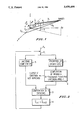
- FIG. 1 shows the position of a target in relation, firstly, to an antenna formed by three aligned acoustic sensors and, secondly, to an antenna formed by three misaligned acoustic sensors;
- FIG. 2 shows a flow chart of the algorithm used.
- the aligned antenna is represented by three sensors C 1 , C 2 and C 3 and the misaligned antenna is shown by the sensors C 1 , C 2 and C 2 , the position of the sensor C 2 resulting from a translation of the central sensor C 2 of the aligned antenna along a vector of misalignment ⁇ having its ends identical with the positions of the sensor C 2 and of the sensor C 2 P .
- the vector ⁇ may occupy any direction of the space around the ideal position of the sensor C 2 , its modulus remaining relatively small compared with the distance L between two consecutive sensors C 1 , C 2 or C 2 , C 3 of the aligned antenna.
- the distance R between the central sensor C 2 and the target and the relative bearing ⁇ of the target with respect to the direction of alignment of the sensors C 1 , C 2 and C 3 are obtained simply from the differences of propagation times ⁇ 12 and ⁇ 23 or time difference of each wave front coming from the target and reaching the sensors C 1 -C 2 and C 2 -C 3 .
- These time differences are defined by the relationships: ##EQU1## where R 1 and R 3 are the respective distances between the sensors C 1 and the target, and c is the velocity of propagation of sound in the medium in which the antenna is submerged.
- ⁇ and R are defined as a function of the differences in propagation times ⁇ 12 and ⁇ 23 by the relationships ##EQU2##
- u represents the standardized vector of the direction of the target and ⁇ ,> symbolizes the scalar product.
- the biased value of the distance can be perfectly determined by the relationship 8.
- the Bias(R) is expressed as a function of the bias of 1 according to the relationship: ##EQU6##
- a vertical misalignment of 10 cm, for a target depth of 400 meters, may give rise to a bias on the distance of about 11%.
- the result of the foregoing is that it is indispensable to take the depth of the target into account, to determine a precise tracking of these targets when the antennas used are not perfectly linear.
- the depth of the target is either determined by a computation or, again, measured by a sonar antenna that is directional in elevation.
- the angle of elevation is estimated on the basis of all the measurements of the differences in the trajectory times.
- the coordinates are all given in a geographic Cartesian reference system of any origin.
- the target is determined at each instant by a state vector X such that:
- the time difference between the sensors C k and C 1 is determined by a relationship of the form: ##EQU7##
- d k which represents the horizontal distance of the target from the sensor, is defined by:
- the submersion term is computed by making the submersion of the central sensor C 2 take place at the instant t. It is defined by the relationship: ##EQU9##
- the estimation algorithm is defined in the manner shown in FIG. 2. It consists, at the step 1, in making a prediction, by means of the relationships (14), of the time differences as a function of each state vector X and then in making a computation, at the step 2, of the residues of estimation between the values of time differences measured between each sensor and the predicted time differences.
- These computations use likelihood maximum and least square estimators in a known way. These likelihood maximum and least square estimators give an estimated value X of the state vector X when the values of the measured and predicted time differences ⁇ (X) are minimum. This minimizing is achieved, for example, by using a known iterative algorithm of the GAUSS NEWTON type, shown in the steps 3 and 4.
- the estimated value X i+1 of the state vector obtained at the i+1th iteration is defined on the basis of the estimated value Xi obtained at the i th by a relationship of the form:
- D i is a value of descent obtained by resolving a least squares problem which minimizes the criterion such that: ##EQU10## where J i is the Jacobian matrix of the function ⁇ (X) evaluated at each estimated vector X i .
- This matrix is computed at the step 5.
- ⁇ is a scalar between -1 and +1 chosen at each iteration so as to minimize the criterion. The iterations stop when the criterion no longer decreases significantly.
- the GAUSS NEWTON algorithm is initialized by a pseudo-linear estimator derived from the method of trajectography by azimuths described, for example, in S. C. NARDONE, A. G. LINDGREN and K. F. GONG, "Fundamental Properties and Performance of Conventional Bearings-Only Motion Analysis” in IEEE Transactions on Automatic Control, Vol. AC-29, No. 9, September 1984.
- This method consists, in a first step, in computing the value of the angle Ak made by the direction of a meridian of the terrestrial geoid with the half-line joining the middle of the space between the sensors C k and C 1 and the target.
- the three pairs of sensors and the n measuring instants are considered to resolve a linear system obtained from the previous relationship, the resolution of which is done by the least squares method, weighted by ⁇ -1 .
- This pseudo-linear estimation enables the initializing of the GAUSS-NEWTON algorithm in position and velocity, the initial elevation being arbitrarily chosen as zero.
- the method that has just been described may also, if necessary, be adapted to the situations in which the elevation can be measured by an independent sonar antenna.
- a sonar at each instant, delivers a measurement taken of the elevation of the target, it may be judicious to use these items of data to compute the trajectography of the target.
- the method of computation uses a method very similar to the previous one. In then referencing the elevation values in relation to the central sensor, the equation of prediction of the elevation values is then: ##EQU13##
- the predicted elevations then have to be included in the vector of the time differences ⁇ (X) while the elevations measured have to be included in the vector of time differences measured.
Abstract
A method for determining the motion of a target in underwater acoustics by means of an antenna with misaligned sensors (C1, C2 P, C3) provided with a central sensor C2 P. It consists in estimating the characteristics of velocity (Vx, Vy) and position of the target x(t*), y(t*) relatively to the antenna by means of a likelihood maximum estimator taking account of the differences in propagation times measured between the wave fronts transmitted by the target and reaching the sensors. The motion estimator is initialized by means of an initial state vector X determined on the basis of the values of the azimuths of the target perceived from the mid-points of each pair of sensors, during a determined number of measurements staggered in time. The action of the state vector X takes place in taking account of the value of the elevation of the target with respect to the antenna.
Description
1. Field of the Invention
The present invention concerns a method for determining the motion of a target in underwater acoustics.
2. Description of the Prior Art
A known method in underwater acoustics to detect the position and motion of submerged targets uses a submerged movable antenna consisting, for example, of three sensors spatially separated from one another. This antenna makes it possible to measure the differences between the propagation times of a signal emitted by a moving target towards the different sensors. In most of the known devices, a description of which may be found in the article by J. C. HASSAB, B. GUIMOND, S. C. NARDONE, "Estimation Of Motion And Location Parameters Of A Moving Source Observed From A Linear Array" in the journal JASA 70(4), October 1981 or again in the IEEE communication by D. J. MURPHY, "Target Tracking With A Linear Array In An Underwater Environment", November 1981, the sensors are aligned and the intermediary sensor is placed strictly at mid-distance between the other two. However, in practice, this arrangement is difficult to meet and the faults in the alignment and position of the sensors introduce errors in the estimation of the positioning and motion of the targets.
It is an aim of the invention to overcome the above-mentioned drawbacks.
To this effect, an object of the invention is a method for determining the motion of a target in underwater acoustics by means of an antenna with misaligned sensors (C1, C2 P, C3) provided with a central sensor C2 P of the type consisting in estimating the characteristics of velocity (Vx, Vy) and position of the target x(t*), y(t*) relatively to the antenna by means of a likelihood maximum estimator taking account of the differences in propagation times measured between the wave fronts transmitted by the target and reaching the sensors, said method consisting in the initializing of the motion estimator by means of an initial state vector X determined on the basis of the values of the azimuths of the target perceived from the mid-points of each pair of sensors, during a determined number of measurements staggered in time, and in estimating the state vector X in taking into account the value of the elevation of the target with respect to the antenna.
Other characteristics and advantages of the invention will appear hereinafter from the following description, made with reference to the appended drawings, of which:
FIG. 1 shows the position of a target in relation, firstly, to an antenna formed by three aligned acoustic sensors and, secondly, to an antenna formed by three misaligned acoustic sensors;
FIG. 2 shows a flow chart of the algorithm used.
In FIG. 1, the aligned antenna is represented by three sensors C1, C2 and C3 and the misaligned antenna is shown by the sensors C1, C2 and C2, the position of the sensor C2 resulting from a translation of the central sensor C2 of the aligned antenna along a vector of misalignment ε having its ends identical with the positions of the sensor C2 and of the sensor C2 P. According to this configuration, the vector ε may occupy any direction of the space around the ideal position of the sensor C2, its modulus remaining relatively small compared with the distance L between two consecutive sensors C1, C2 or C2, C3 of the aligned antenna.
In considering only what happens with an aligned antenna, the distance R between the central sensor C2 and the target and the relative bearing θ of the target with respect to the direction of alignment of the sensors C1, C2 and C3 are obtained simply from the differences of propagation times τ12 and τ23 or time difference of each wave front coming from the target and reaching the sensors C1 -C2 and C2 -C3. These time differences are defined by the relationships: ##EQU1## where R1 and R3 are the respective distances between the sensors C1 and the target, and c is the velocity of propagation of sound in the medium in which the antenna is submerged. Taking only second order terms, θ and R are defined as a function of the differences in propagation times τ12 and τ23 by the relationships ##EQU2##
Naturally, in the presence of a misaligned antenna, the differences in propagation times obtained are no longer equal to the time differences τ12 and τ13. Taking only terms of the first order in ##EQU3## the distance RP between the sensor C2 P and the target is then defined by an expression of the form:
R.sup.P =R-<u,ε> (5)
where u represents the standardized vector of the direction of the target and <,> symbolizes the scalar product.
The differences in propagation times τ12 P and τ23 of the sound wave coming from the target between, respectively, sensors C1 -C2 P and C2 P -C3 are defined by relationships of the form:
τ.sub.12.sup.P =τ.sub.12 +<u,ε>/c (6)
τ.sub.23.sup.P =τ.sub.23 -<u,ε>/c (7)
The relationships 6 and 7 show that the misalignment of the sensors on the antenna has an effect on the propagation times measured by the sensors and that, consequently, it should have an effect also on the computation of the position of the target. In particular, the appreciation of the distance R should be considered to be biased by the value: ##EQU4##
If both the alignment fault ε and the direction u are perfectly known, the biased value of the distance can be perfectly determined by the relationship 8.
However, in practice, only ε can be perfectly determined, and there always remains an error of appreciation of the direction u of the target.
If we consider an orthonormal reference (o, x, y, z), the relationship 8 should be considered as a resultant of the sum of a distance biased in the horizontal plane (o, x, y) and a distance biased in a vertical direction oz normal to this plane such that: ##EQU5##
When the target is localized in the horizontal plane, the components of the vector u in this plane ux and uy can be estimated properly. The errors δux and δuy are very close to 0, and the bias on the distance is above all determined by the uncertainty on δuz.
The Bias(R) is expressed as a function of the bias of 1 according to the relationship: ##EQU6##
By way of indication, a vertical misalignment of 10 cm, for a target depth of 400 meters, may give rise to a bias on the distance of about 11%.
The result of the foregoing is that it is indispensable to take the depth of the target into account, to determine a precise tracking of these targets when the antennas used are not perfectly linear.
According to the invention, the depth of the target is either determined by a computation or, again, measured by a sonar antenna that is directional in elevation.
In the following computations, it is assumed that the target shifts at constant velocity V in a horizontal plane of submersion Z. According to the first method, the angle of elevation is estimated on the basis of all the measurements of the differences in the trajectory times.
The coordinates are all given in a geographic Cartesian reference system of any origin. The target is determined at each instant by a state vector X such that:
X=[x(t*), y(t*), V.sub.x, V.sub.y, S(t*)].sup.T
where x(t*) and y(t*) define the components of distance of the vector in a horizontal plane and Vx and Vy determine its components of velocity in this same plane. This vector naturally relates to the instant of estimation t* and is used to reconstruct the trajectory Xt, Yt of the target by integration.
At any instant, the time difference between the sensors Ck and C1, for example, is determined by a relationship of the form: ##EQU7##
The distance Rk(t) between the target and the sensor Ck is given by a relationship of the form: ##EQU8##
where dk which represents the horizontal distance of the target from the sensor, is defined by:
d.sub.k (t).sup.2 =(x(t)-C.sub.k.sbsb.x (t)).sup.2 +(y(t)-C.sub.k.sbsb.y (t)).sup.2 (16)
The submersion term is computed by making the submersion of the central sensor C2 take place at the instant t. It is defined by the relationship: ##EQU9##
The foregoing formulae (14) to (17) enable the prediction of the time differences τ(X) as a function of the state vector X to be estimated.
The estimation algorithm is defined in the manner shown in FIG. 2. It consists, at the step 1, in making a prediction, by means of the relationships (14), of the time differences as a function of each state vector X and then in making a computation, at the step 2, of the residues of estimation between the values of time differences measured between each sensor and the predicted time differences. These computations use likelihood maximum and least square estimators in a known way. These likelihood maximum and least square estimators give an estimated value X of the state vector X when the values of the measured and predicted time differences τ(X) are minimum. This minimizing is achieved, for example, by using a known iterative algorithm of the GAUSS NEWTON type, shown in the steps 3 and 4.
According to this algorithm, the estimated value Xi+1 of the state vector obtained at the i+1th iteration is defined on the basis of the estimated value Xi obtained at the ith by a relationship of the form:
X.sub.i+1 =X.sub.i +μD.sub.i (18)
where Di is a value of descent obtained by resolving a least squares problem which minimizes the criterion such that: ##EQU10## where Ji is the Jacobian matrix of the function τ(X) evaluated at each estimated vector Xi.
This matrix is computed at the step 5.
Γ is a scalar between -1 and +1 chosen at each iteration so as to minimize the criterion. The iterations stop when the criterion no longer decreases significantly.
In the method that has just been described, the GAUSS NEWTON algorithm is initialized by a pseudo-linear estimator derived from the method of trajectography by azimuths described, for example, in S. C. NARDONE, A. G. LINDGREN and K. F. GONG, "Fundamental Properties and Performance of Conventional Bearings-Only Motion Analysis" in IEEE Transactions on Automatic Control, Vol. AC-29, No. 9, September 1984. This method consists, in a first step, in computing the value of the angle Ak made by the direction of a meridian of the terrestrial geoid with the half-line joining the middle of the space between the sensors Ck and C1 and the target.
This computation is done by applying the relationship: ##EQU11##
According to a second step, the value of the azimuth is put into an equation according to the relationship: ##EQU12##
And, finally, in a third step, the three pairs of sensors and the n measuring instants are considered to resolve a linear system obtained from the previous relationship, the resolution of which is done by the least squares method, weighted by Σ-1.
This pseudo-linear estimation enables the initializing of the GAUSS-NEWTON algorithm in position and velocity, the initial elevation being arbitrarily chosen as zero.
The method that has just been described may also, if necessary, be adapted to the situations in which the elevation can be measured by an independent sonar antenna. For, if in addition to the antenna device that has just been described, a sonar, at each instant, delivers a measurement taken of the elevation of the target, it may be judicious to use these items of data to compute the trajectography of the target. In this case, the method of computation uses a method very similar to the previous one. In then referencing the elevation values in relation to the central sensor, the equation of prediction of the elevation values is then: ##EQU13##
The predicted elevations then have to be included in the vector of the time differences τ(X) while the elevations measured have to be included in the vector of time differences measured.
To initialize the GAUSS NEWTON algorithm, the elevation that is taken into account is equal to the mean of the elevation values obtained, giving: ##EQU14##
This elevation value is then taken into account for the computation of the azimuths according to the relationship: ##EQU15##
The implementation of the method of the invention could advantageously be done by means of one or more suitably programmed signal processing microprocessors. This implementation is within the scope of those skilled in the art.
Claims (4)
1. A method for determining the motion of a target in underwater acoustics by means of an antenna with misaligned sensors (C1, C2 P, C3) provided with a central sensor C2 P, comprising the steps of:
estimating the characteristics of velocity (Vx, Vy) and position of the target X (t*), Y (t*) relative to the antenna by means of a motion estimator;
applying a GAUSS NEWTON iterative algorithm taking into account the differences in propagation times measured between fronts transmitted by the target and reaching the sensors, said method further comprising the steps of;
initializing the GAUSS NEWTON algorithm of the motion estimator by means of an initial state vector X determined on the basis of the values of azimuths AKI of the target perceived from the mid-points of each pair of sensors, during a determined number of measurements staggered in time; and
estimating the state vector X by taking into account the value of the elevation of the target with respect to the antenna, with the horizontal coordinates of the position of the target and its velocity vectors being determined for initializing the GAUSS NEWTON algorithm by resolving a system of equations determined for each sensor pair by the matrix relationship; ##EQU16##
2. A method according to claim 1, wherein the value of the elevation is computed by making the submersion of the central sensor occur at the instant of estimation.
3. A method according to claim 2, wherein the value of the elevation is measured with an additional sonar antenna.
4. A method according to claim 3, wherein the GAUSS NEWTON algorithm is initialized by taking into account the mean of the elevations measured during a determined number N of measurements.
Applications Claiming Priority (2)
| Application Number | Priority Date | Filing Date | Title |
|---|---|---|---|
| FR8906662A FR2647224B1 (en) | 1989-05-22 | 1989-05-22 | METHOD FOR DETERMINING THE MOVEMENT OF A TARGET IN UNDERWATER ACOUSTICS |
| FR8906662 | 1989-05-22 |
Publications (1)
| Publication Number | Publication Date |
|---|---|
| US5036498A true US5036498A (en) | 1991-07-30 |
Family
ID=9381876
Family Applications (1)
| Application Number | Title | Priority Date | Filing Date |
|---|---|---|---|
| US07/524,804 Expired - Fee Related US5036498A (en) | 1989-05-22 | 1990-05-18 | Method for determining the motion of a target in underwater acoustics |
Country Status (4)
| Country | Link |
|---|---|
| US (1) | US5036498A (en) |
| EP (1) | EP0399860B1 (en) |
| DE (1) | DE69007539T2 (en) |
| FR (1) | FR2647224B1 (en) |
Cited By (4)
| Publication number | Priority date | Publication date | Assignee | Title |
|---|---|---|---|---|
| US5276390A (en) * | 1991-10-04 | 1994-01-04 | Hewlett-Packard Company | System for hybrid position and force control |
| US5377162A (en) * | 1992-10-08 | 1994-12-27 | L'etat Francais (Represented By The Deleque General For L'armement) | Underwater object passive tracking process and device |
| US5537511A (en) * | 1994-10-18 | 1996-07-16 | The United States Of America As Represented By The Secretary Of The Navy | Neural network based data fusion system for source localization |
| DE19633884B4 (en) * | 1996-08-19 | 2004-09-02 | Siemens Ag | Method for determining the object position of an object |
Families Citing this family (4)
| Publication number | Priority date | Publication date | Assignee | Title |
|---|---|---|---|---|
| FR2835619B1 (en) * | 2002-02-05 | 2004-04-02 | Thales Sa | PASSIVE LOCATION SYSTEM FOR AN UNDERWATER MOBILE OBJECT |
| DE102007022563A1 (en) * | 2007-05-14 | 2008-11-27 | Atlas Elektronik Gmbh | Method for locating a sounding target |
| CN110132283A (en) * | 2019-05-28 | 2019-08-16 | 中国人民解放军火箭军工程大学 | A kind of UAV electro-optical's platform is to ground static target localization method and system |
| CN114234982B (en) * | 2021-12-20 | 2024-04-16 | 中南大学 | Three-dimensional track planning method, system, equipment and medium based on azimuth positioning |
Citations (2)
| Publication number | Priority date | Publication date | Assignee | Title |
|---|---|---|---|---|
| US4162474A (en) * | 1964-09-21 | 1979-07-24 | Sperry Rand Corporation | Yaw-compensated correlating sonar tracking system |
| EP0288374A1 (en) * | 1987-04-24 | 1988-10-26 | Thomson-Csf | Passive telemetry method using sound |
-
1989
- 1989-05-22 FR FR8906662A patent/FR2647224B1/en not_active Expired - Lifetime
-
1990
- 1990-05-04 EP EP90401199A patent/EP0399860B1/en not_active Expired - Lifetime
- 1990-05-04 DE DE69007539T patent/DE69007539T2/en not_active Expired - Fee Related
- 1990-05-18 US US07/524,804 patent/US5036498A/en not_active Expired - Fee Related
Patent Citations (2)
| Publication number | Priority date | Publication date | Assignee | Title |
|---|---|---|---|---|
| US4162474A (en) * | 1964-09-21 | 1979-07-24 | Sperry Rand Corporation | Yaw-compensated correlating sonar tracking system |
| EP0288374A1 (en) * | 1987-04-24 | 1988-10-26 | Thomson-Csf | Passive telemetry method using sound |
Non-Patent Citations (4)
| Title |
|---|
| Journal of Acoustical Society of America, vol. 70, No. 4, Oct. 1981, pp. 1054 1061, New York, U.S.; J. C. Hassab et al.: Estimation of location and motion parameters of a moving source observed from a linear array . * |
| Journal of Acoustical Society of America, vol. 70, No. 4, Oct. 1981, pp. 1054-1061, New York, U.S.; J. C. Hassab et al.: "Estimation of location and motion parameters of a moving source observed from a linear array". |
| Journal of the Acoustical Society of America, vol. 76, No. 4, Oct. 1984, pp. 1114 1122, Acoustical Society of America, New York, U.S.; F. Dommermuth et al.: Estimating the trajectory of an accerlationless aircraft by means of a stationary acoustic sensor . * |
| Journal of the Acoustical Society of America, vol. 76, No. 4, Oct. 1984, pp. 1114-1122, Acoustical Society of America, New York, U.S.; F. Dommermuth et al.: "Estimating the trajectory of an accerlationless aircraft by means of a stationary acoustic sensor". |
Cited By (4)
| Publication number | Priority date | Publication date | Assignee | Title |
|---|---|---|---|---|
| US5276390A (en) * | 1991-10-04 | 1994-01-04 | Hewlett-Packard Company | System for hybrid position and force control |
| US5377162A (en) * | 1992-10-08 | 1994-12-27 | L'etat Francais (Represented By The Deleque General For L'armement) | Underwater object passive tracking process and device |
| US5537511A (en) * | 1994-10-18 | 1996-07-16 | The United States Of America As Represented By The Secretary Of The Navy | Neural network based data fusion system for source localization |
| DE19633884B4 (en) * | 1996-08-19 | 2004-09-02 | Siemens Ag | Method for determining the object position of an object |
Also Published As
| Publication number | Publication date |
|---|---|
| FR2647224A1 (en) | 1990-11-23 |
| DE69007539D1 (en) | 1994-04-28 |
| FR2647224B1 (en) | 1992-04-30 |
| DE69007539T2 (en) | 1994-07-21 |
| EP0399860A1 (en) | 1990-11-28 |
| EP0399860B1 (en) | 1994-03-23 |
Similar Documents
| Publication | Publication Date | Title |
|---|---|---|
| Smith et al. | The spherical interpolation method of source localization | |
| Smith et al. | Closed-form least-squares source location estimation from range-difference measurements | |
| US5525997A (en) | Self-calibrating, eigenstructure based method and means of direction finding | |
| US5357484A (en) | Method and apparatus for locating an acoustic source | |
| US5036498A (en) | Method for determining the motion of a target in underwater acoustics | |
| US5192955A (en) | Individual target angle measurements in a multiple-target environment | |
| Park et al. | Multiple target angle tracking algorithm using predicted angles | |
| Gingras et al. | Electromagnetic matched-field processing: Basic concepts and tropospheric simulations | |
| US6028823A (en) | Geodetic position estimation for underwater acoustic sensors | |
| Schmidt et al. | Physics-imposed resolution and robustness issues in seismo-acoustic parameter inversion | |
| Vincent et al. | Geodetic position estimation of underwater acoustic sensors | |
| Sandkuhler et al. | Accuracy of maximum-likelihood estimates for array processing | |
| Chen et al. | VLF source localization with a freely drifting acoustic sensor array | |
| Kirsteins | Blind separation of signal and multipath interference for synthetic aperture sonar | |
| Tran et al. | Array surveying using matched‐field processing | |
| Farina et al. | Space-time processing for AEW radar | |
| Hassab | Homomorphic deconvolution in reverberant and distortional channels: an analysis | |
| Smith et al. | Underwater target tracking using signal subspace TDOA and differential doppler | |
| Lee et al. | Robust adaptive matched-field-processing | |
| Byrne | Effects of modal phase errors on eigenvector and nonlinear methods for source localization in matched‐field processing | |
| Charge et al. | Cyclostationarity-exploiting direction finding algorithms | |
| Whinnett et al. | High-resolution array processing methods for joint direction-velocity estimation | |
| Rockah et al. | Source localization with two dimensional array subject to uncertainty in sensor location | |
| Zheng et al. | One-dimensional MODE algorithm for two-dimensional frequency estimation | |
| Tweg et al. | Numerical optimization method for array signal processing |
Legal Events
| Date | Code | Title | Description |
|---|---|---|---|
| AS | Assignment |
Owner name: THOMSON-CSF, 51, ESPLANADE DU GENERAL DE GAULLE 92 Free format text: ASSIGNMENT OF ASSIGNORS INTEREST.;ASSIGNOR:VAN CAPPEL, DOMINIQUE;REEL/FRAME:005648/0943 Effective date: 19900420 |
|
| FEPP | Fee payment procedure |
Free format text: PAYOR NUMBER ASSIGNED (ORIGINAL EVENT CODE: ASPN); ENTITY STATUS OF PATENT OWNER: LARGE ENTITY |
|
| FPAY | Fee payment |
Year of fee payment: 4 |
|
| REMI | Maintenance fee reminder mailed | ||
| LAPS | Lapse for failure to pay maintenance fees | ||
| FP | Lapsed due to failure to pay maintenance fee |
Effective date: 19990730 |
|
| STCH | Information on status: patent discontinuation |
Free format text: PATENT EXPIRED DUE TO NONPAYMENT OF MAINTENANCE FEES UNDER 37 CFR 1.362 |