US5030353A - Secondary sewage treatment system - Google Patents
Secondary sewage treatment system Download PDFInfo
- Publication number
- US5030353A US5030353A US07/559,427 US55942790A US5030353A US 5030353 A US5030353 A US 5030353A US 55942790 A US55942790 A US 55942790A US 5030353 A US5030353 A US 5030353A
- Authority
- US
- United States
- Prior art keywords
- zone
- tank
- turbulent
- media
- treatment
- Prior art date
- Legal status (The legal status is an assumption and is not a legal conclusion. Google has not performed a legal analysis and makes no representation as to the accuracy of the status listed.)
- Expired - Lifetime
Links
Images
Classifications
-
- C—CHEMISTRY; METALLURGY
- C02—TREATMENT OF WATER, WASTE WATER, SEWAGE, OR SLUDGE
- C02F—TREATMENT OF WATER, WASTE WATER, SEWAGE, OR SLUDGE
- C02F3/00—Biological treatment of water, waste water, or sewage
- C02F3/02—Aerobic processes
- C02F3/08—Aerobic processes using moving contact bodies
- C02F3/085—Fluidized beds
- C02F3/087—Floating beds with contact bodies having a lower density than water
-
- C—CHEMISTRY; METALLURGY
- C02—TREATMENT OF WATER, WASTE WATER, SEWAGE, OR SLUDGE
- C02F—TREATMENT OF WATER, WASTE WATER, SEWAGE, OR SLUDGE
- C02F3/00—Biological treatment of water, waste water, or sewage
- C02F3/02—Aerobic processes
- C02F3/12—Activated sludge processes
- C02F3/20—Activated sludge processes using diffusers
-
- C—CHEMISTRY; METALLURGY
- C02—TREATMENT OF WATER, WASTE WATER, SEWAGE, OR SLUDGE
- C02F—TREATMENT OF WATER, WASTE WATER, SEWAGE, OR SLUDGE
- C02F3/00—Biological treatment of water, waste water, or sewage
- C02F3/02—Aerobic processes
- C02F3/12—Activated sludge processes
- C02F3/22—Activated sludge processes using circulation pipes
- C02F3/223—Activated sludge processes using circulation pipes using "air-lift"
-
- Y—GENERAL TAGGING OF NEW TECHNOLOGICAL DEVELOPMENTS; GENERAL TAGGING OF CROSS-SECTIONAL TECHNOLOGIES SPANNING OVER SEVERAL SECTIONS OF THE IPC; TECHNICAL SUBJECTS COVERED BY FORMER USPC CROSS-REFERENCE ART COLLECTIONS [XRACs] AND DIGESTS
- Y02—TECHNOLOGIES OR APPLICATIONS FOR MITIGATION OR ADAPTATION AGAINST CLIMATE CHANGE
- Y02W—CLIMATE CHANGE MITIGATION TECHNOLOGIES RELATED TO WASTEWATER TREATMENT OR WASTE MANAGEMENT
- Y02W10/00—Technologies for wastewater treatment
- Y02W10/10—Biological treatment of water, waste water, or sewage
Definitions
- This invention relates to on-site waste water treatment systems, and more particularly to secondary treatment systems.
- a primary object of the present invention is to provide a secondary sewage treatment system intended to operate in conjunction with a conventional septic system.
- the system of this invention is designed to be interposed between the septic tank and drainfield to provide a satisfactory effluent to the drainfield.
- the present system is specially designed for use in commercial treatment systems that must handle food preparation wastes; and in this environment the system provides an effluent comparable to that which would be produced from a conventional residential septic tank.
- the system of this invention biologically treats biodegradable wastes through aerobic microbial growth on media resulting in the biological oxidation of the waste products.
- the preferred embodiment of this invention functions as an aeration tank, settling tank and aerobic digester in a single unit.
- This invention uses buoyant media, as contrasted with fixed or packed media, and consequently does not incur flocculent build-up during operation or the consequent clogging typical of fixed or packed media treatment systems.
- biological growth takes place in a mixing zone filled with a bouyant media.
- the bouyant media has a high surface area to volume ratio, a low resistance to liquid flow and a surface condition receptive to aerobic microbial growth.
- Waste flow from a septic tank enters the system into a turbulent zone above the mixing zone and begins a continuous cycle, flowing down through the mixing zone and then upward through draft tubes from which it is re-introduced to the turbulent zone.
- the mixing zone is filled with the bouyant media and the waste flows gently down through the mixing zone in contact with the buoyant media surfaces.
- the draft tubes are free of buoyant media or any other surfaces on which biomass can collect.
- the waste liquor is drawn turbulently up through the draft tubes and spills out above the mixing zone into the turbulent zone
- the turbulent zone is likewise free of buoyant media or any other surfaces on which biomass can collect.
- the boiling action of the liquor including detergents and other foaming products, produces a foam which accumulates in the area immediately above the turbulant zone.
- This foaming action provides additional treatment action, with bacteria being evident in the foam, and also enables the system to tolerate occasional overloading such as occurs during peak hours of operation in food service establishments.
- the system produces more foaming, in which a significant amount of suspended solids and grease and oils are held, thereby delaying treament of these wastes until the system can tolerate them; at which time the foam settles through the turbulent zone into the mixing zone and is incorporated in the waste liquor.
- the system provides a settling zone below the mixing zone through which sludge may settle out for separate removal and from which the treated liquor effluent may be discharged into the drainfield.
- the treated liquor is collected through a manifold positioned midway between the bottom of the mixing zone and the top of the sludge-collecting zone. It then flows through a riser into an outlet leading to the septic system drainfield.
- FIG. 1 is a vertical side elevation view, in cross section, of an exemplary embodiment illustrating the principals of operation of the system of this invention
- FIG. 2 is a top plan view of a preferred embodiment of the apparatus of this invention.
- FIG. 3 is a cross section view taken along the line 3--3 in FIG. 2;
- FIG. 4 is a cross section view taken along the line 4--4 in FIG. 2;
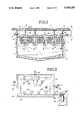
- FIG. 5 is a top plan view of another embodiment of the apparatus of this invention.
- FIG. 6 is a cross section view taken along the line 6--6 in FIG. 5;
- FIG. 7 is a cross section view taken along the line 7--7 in FIG. 5;
- FIG. 8 is a detailed view of the draft tube segment of the FIG. 2 apparatus
- FIG. 9 is a detailed view of the effluent outlet manifold of the FIG. 2 apparatus.
- FIG. 10 is a partial view of the air discharge tube employed in the FIG. 8 draft tube segment.
- the on-site waste water treatment system as herein described may be used for treatment of residential or commercial wastes. However, its primary intended use is for treating commercial wastes which ordinarily cannot be treated with conventional septic systems.
- the typical effluent from residential and commercial business establishments consists primarily of human waste in admixture with biodegradable materials such as food and other materials associated with food preparation.
- the waste water to be treated generally contains gravity settleable solids. While any means of effecting solid-liquid separation may be used, the most commonly used method is a septic tank into which the waste water is discharged and the solids allowed to settle by gravity.
- the effluent leaving the septic tank, or other settling system is directed into the system of the present invention.
- the system of the present invention is provided in a concrete tank 1.
- the tank 1 has a lid 2, and upper and lower halves 3 and 4. Within the upper half 3, waste influent inlet 5 and waste liquor outlet 6 are provided. Below the level of the inlet and outlet, a grating 7 is provided that extends across the area of the tank interior, from wall-to-wall.
- a plurality of draft tubes 8 are located and positioned in the tank such that they open at the top co-planar with the top surface of the grating 7 and extend down into the tank to open at their lower ends a distance below the grating 7.
- the bottom of the tank 1 is sloped to provide a centralized low point.
- This structure provides a sludge-collecting zone 9 at the bottom of the tank, a settling zone 10 extending above the sludge-collecting zone, a media mixing and aerating zone 11 extending above the settling zone and generally defined by the length of draft tubes 8 inasmuch as it extends from just below the bottom ends of the draft tubes to the grating 7, a turbulent zone 12 extending from the grating 7 to the elevation of the influent inlet 5, and a foam-collecting zone 13 above the turbulent zone 12.
- An air delivery conduit 14 delivers air via a manifold 15 embedded in the tank lid 2 to individual air delivery tubes 16, one being provided for each draft tube 8.
- the air delivery tubes 16 extend axially down into the draft tubes 8 and terminate above the bottom end of each respective draft tube.
- a multiplicity of buoyant media, such as spheres 17, are contained within the tank below the grating 7.
- the tank 1 is filled with waste fluid up to the level of the outlet 6.
- the buoyant media 17 float and are confined beneath the grating 7 within the media mixing and aerating zone 11; zone 11 being essentially filled with the media 17.
- the media are preferably composed of bouyant hollow plastic spheres that provide a high surface area to volume ratio on the order of 38 sq. ft./cu. ft. or more
- Each draft tube - air delivery conduit assembly comprises an air diffuser 18 through which air is ejected into the system without disturbing the surrounding media mixing and aerating zone 11.
- influent entering the tank 1 is circulated through the media 17 by the pumping action of the air diffusers 18.
- air diffusers 18 As air is discharged into the draft tubes 8, it aerates the liquor within the draft tubes as it rises.
- the waste liquor is churned and pumped along with the rising air up and out of the draft tubes into the turbulent zone 12.
- the liquor flows gently down through the mixing zone 11, passing through the buoyant media 17 (i.e. around the individual spheres that make up the media). From the bottom of the mixing zone 11, the liquor passes vertically through the separate passageways, provided by the draft tubes 8, between the bottom and top of the mixing zone 11.
- the air forced into the draft tubes induces a pumping action while aerating the liquor passing upward in the draft tubes.
- the flow within these vertical passageways is relatively turbulent.
- the volume of air used and the proximity of the vertical flow passageways is such that the outlet circles 19 of flow turbulence between adjacent draft tubes overlap.
- the liquor is continuously circulated in a flow path, including the mixing zone 11 and the vertical flow passageways, at a flow rate and under conditions suitable for promoting thorough mixing of the liquor with the buoyant media, and suitable for maintaining aerobic microbial growth on the buoyant media. If the flow rate of the liquor through the mixing zone 11 is too turbulent, microbial growth will be washed off the buoyant media. On the other hand, if the flow rate through the buoyant media is too slow, excessive microbal growth will accumulate and may cause clogging. When the flow rate is correct, excessive microbial growth falls off the buoyant media and is naturally recycled. Because the media is not fixed or packed, the individual buoyant elements that make up the buoyant media can rotate and tip over as growth builds up.
- the buoyant media is thus self-cleaning. Dead growth will fall from the buoyant media and settle through the settling zone 10, forming sludge in the sludge-collecting zone 9. Periodically the sludge may be pumped out and discarded or recyled.
- FIGS. 2-4 One preferred embodiment that incorporates the features of the FIG. 1 system and functions in accordance with the description of the FIG. 1 system is shown in FIGS. 2-4. A similar system is shown in FIGS. 5-6.
- this embodiment comprises a cast concrete tank 101 having top and bottom halves 103 and 104 joined at a circumferential seam, and a lid 102.
- the lid is provided with a plurality of air diffuser openings arranged in two rows, each opening being closed by a traffic-bearing clean-out cover 120, and a pair of access openings located between the two rows of air diffuser openings.
- the access openings are closed by traffic-bearing steel doors 121-122.
- the access openings are separated by a mid-span lid portion that contains a sludge pump-out opening closed by a traffic-bearing clean-out cover 123.
- An influent inlet conduit 105 enters from the side of the tank 101 and branches at a Tee toward the center of the tank to provide two influent discharge openings into the tank's interior.
- An effluent discharge conduit 106 enters from one end of the tank 101 and is connected to a liquor-collecting manifold 124 by a riser 125.
- Manifold 124 is located between the bottom of the settling zone and the top of the sludge-collecting zone.
- a grating 107 is positioned within the tank's interior and fastened to the tank inner wall by brackets 126.
- the grating 107 is positioned just below the elevation of the outlet conduit 106 as shown. Axially below the air diffuser openings, the grating 107 is provided with apertures for the draft tubes 108.
- Draft tubes 108 are provided that extend from the lid air diffuser openings and downward through the grating 107 into the tank's interior. The draft tubes are secured to the lid at their respective lid openings and stabilized by the grating 107.
- Each draft tube is provided with longitudinal cut-out openings 127 in it's side wall, above the grating 107, that span the turbulent zone's depth to provide for liquor flow from the draft tube interiors into the turbulent zone.
- An air inlet conduit 114 connects to a manifold conduit 115 embedded in the tank lid.
- Individual air delivery tubes 116 are connected to the manifold conduit 115 and extended down into the draft tubes to provide, in conjunction with the draft tubes, the multiple air diffuser assemblies 118 required by this invention.
- the bottom end of each air delivery tube 116 is capped and provided with radial apertures 129 through the cap 128 and the tube wall for discharge of air into the draft tube passageway. This capped feature prevents bouyant media elements from accidentally becoming lodged in the draft tubes, as might tend to occur while the tank is being filled for example.
- the mixing zone is substantially filled with the buoyant media elements 117.
- the bottom outlet manifold conduit 124 is provided with several downward-opening inlets 130 as shown in FIGS. 3 and 4. These large openings prevent the manifold from becoming anaerobic.
- the semi-clarified effluent liquor passes through a plurality of apertures 131. These apertures, as shown in FIG. 9, are located below the mid-line of the manifold conduit so that settling particulates will not fall into the apertures.
- Air is supplied to the system by air pumping system 135, comprising a fan 136 and an air pressure and volume regulator 137. Excess air is vented from the tank 107 through air vent conduit 138 extending into the foam collecting zone.
- a sludge removal conduit 140 extends downward from the top lid clean-out opening to the bottom of the tank for removal of sludge from the sludge-collecting zone. Side openings are provided in the bottom removal conduit 140, as shown in FIGS. 3 and 4 to facilitate sludge removal.
- a 1680 gallon tank sized as shown in FIGS. 2-4 would conveniently hold 100 cubic feet of 3.5 inch diameter Jaeger Tri-Pak Polypropylene media elements. This media has a ratio of 38 square feet of area per cubic foot of volume. This would yield 3800 square feet of media area.
- Compressed air could be supplied by a 2.5 horsepower Gast model R5125-1 fan at 160 cfm free air.
- a unit of this capacity could handle 700 gallons of waste water from a restaurant per day and yield household-type effluent to the drainfield after a 58 hour retention time at maximum hydraulic capacity. If lower waste strength is desired, the unit could be operated at a lower flow rate or two such units could be connected in series between the septic tank and the drainfield.
- This unit has demonstrated that it has the capacity to cope with shock loading, whether due to increases in waste strength or hydraulic loading or both. In normal operation, the unit does not accumulate sludge in the sludge-collecting zone and there will be little or no need for periodic pump outs.
- FIGS. 5-6 The embodiment shown in FIGS. 5-6 is similar in most structural respects to the FIGS. 2-4 embodiment.
- the grating 207 and the draft tubes 208 are supported in a different manner within the tank 201.
- the draft tubes 208 do not extend above the turbulent zone inasmuch as they are supported from below, rather than from the overhead tank lid as in the FIGS. 2-4 embodiment.
- the grating 207 is supported on brackets 250 that also extend inward to enclose one of the draft tubes 208 at their outer ends, as shown in FIG. 7.
- the tank lid is configured differently.
- the lid is provided with a longitudinal rectangular maintainance opening covered by a non-metallic walkway cover 251.
- a tank cover having a pair of triangular end walls 252 and 253, and with hinged panels 254 and 255 that overlap at their apex to form a weather-tight roof.
- the end panels are vented at 256 so that excess air from the tank 207 can escape through the walkway 251 to the atmosphere.
- Roof mounting hinge sets 257 and 258 are attached to tank 207 as shown in FIG. 7.
- the roof structure may be made of light weight material such as fiberglass so that installation is convenient.
- a secondary sewage treatment system is provided with vertically-aligned foam collecting, turbulent, mixing, settling, and sludge collecting zones.
- a grating defines the boundary between the turbulent and mixing zones. Beneath the grating, a bouyant media, such as hollow plastic spheres, are contained and occupy substantially all of the mixing zone.
- Air diffusers including elongated draft tubes extend from the turbulent zone down through the mixing zone for introduction of air to aerate waste water liquor and to cause the aerated liquor to recirculate up into the turbulent zone, thereby creating a circulation of waste water liquor from the turbulent zone, down through the mixing zone and around the bouyant media, and up through the draft tubes to the turbulent zone.
Abstract
Description
Claims (14)
Priority Applications (1)
Application Number | Priority Date | Filing Date | Title |
---|---|---|---|
US07/724,836 US5202027A (en) | 1989-01-13 | 1991-07-02 | Secondary sewage treatment system |
Applications Claiming Priority (1)
Application Number | Priority Date | Filing Date | Title |
---|---|---|---|
US29729489A | 1989-01-13 | 1989-01-13 |
Related Parent Applications (1)
Application Number | Title | Priority Date | Filing Date |
---|---|---|---|
US29729489A Continuation | 1989-01-13 | 1989-01-13 |
Related Child Applications (1)
Application Number | Title | Priority Date | Filing Date |
---|---|---|---|
US07/724,836 Continuation-In-Part US5202027A (en) | 1989-01-13 | 1991-07-02 | Secondary sewage treatment system |
Publications (1)
Publication Number | Publication Date |
---|---|
US5030353A true US5030353A (en) | 1991-07-09 |
Family
ID=23145705
Family Applications (1)
Application Number | Title | Priority Date | Filing Date |
---|---|---|---|
US07/559,427 Expired - Lifetime US5030353A (en) | 1989-01-13 | 1990-07-23 | Secondary sewage treatment system |
Country Status (4)
Country | Link |
---|---|
US (1) | US5030353A (en) |
AU (1) | AU660149B2 (en) |
CA (1) | CA2108373C (en) |
WO (1) | WO1992021619A1 (en) |
Cited By (36)
Publication number | Priority date | Publication date | Assignee | Title |
---|---|---|---|---|
US5200081A (en) * | 1989-01-13 | 1993-04-06 | Stuth William L | Secondary sewage treatment system |
US5202027A (en) * | 1989-01-13 | 1993-04-13 | Stuth William L | Secondary sewage treatment system |
US5205935A (en) * | 1992-02-10 | 1993-04-27 | Aaa Environmental Services Corp. | High performance fixed film bioreactor |
US5232586A (en) * | 1992-09-25 | 1993-08-03 | Malone Ronald F | Floating media hourglass biofilter |
WO1994016999A1 (en) * | 1991-07-02 | 1994-08-04 | Stuth William L | Secondary sewage treatment system |
US5358636A (en) * | 1993-05-18 | 1994-10-25 | Gaetan Brouillard | Apparatus for the treatment of waste sludge |
US5387335A (en) * | 1990-11-21 | 1995-02-07 | Iwai; Isamu | Filter circulating type sewage disposal apparatus |
US5413749A (en) * | 1993-06-04 | 1995-05-09 | Wheelabrator Engineered Systems Inc. | Process of making beads for a liquid purification bed |
US5609754A (en) * | 1995-09-07 | 1997-03-11 | Stuth; William L. | Secondary sewage treatment system |
US5676828A (en) * | 1995-02-01 | 1997-10-14 | Fluidyne, Inc. | Apparatus and method for modifying waste water |
US5770080A (en) * | 1997-04-23 | 1998-06-23 | Malone; Ronald F. | Air charged backwashing bioclarifier |
US6162020A (en) * | 1998-12-04 | 2000-12-19 | Nca2Bioprocess, Inc. | Airlift pump apparatus and method |
US6187183B1 (en) | 1997-05-02 | 2001-02-13 | Septitech, Inc. | Waste water treatment process and system with filtering media |
US6277274B1 (en) * | 1999-04-16 | 2001-08-21 | Larry Steven Coffman | Method and apparatus for treating stormwater runoff |
US6517724B1 (en) | 1998-04-16 | 2003-02-11 | Ronald F. Malone | Air charged backwashing bioclarifier |
US6616845B2 (en) | 2001-05-29 | 2003-09-09 | Aqwise Wise Water Technologies, Ltd. | Method and apparatus for biological wastewater treatment |
US6638422B1 (en) * | 1999-11-03 | 2003-10-28 | Steven H. Schwartzkopf | Liquid filtration apparatus and method embodying filtration particles having specific gravity less than liquid being filtered |
US20040089592A1 (en) * | 2001-05-29 | 2004-05-13 | Shechter Ronen Itzhak | Method, apparatus and biomass support element for biolocical waste water treatment |
US20050029204A1 (en) * | 2003-08-04 | 2005-02-10 | Schwartzkopf Steven H. | Liquid filtration apparatus and method embodying super-buoyant filtration particles |
US20050189281A1 (en) * | 2002-06-14 | 2005-09-01 | Cornell Research Foundation, Inc. | Cellular microbead filter for use in water recirculating system |
US6942788B1 (en) | 2003-05-29 | 2005-09-13 | Pentair Pump Group, Inc. | Growth media wastewater treatment reactor |
US7014769B1 (en) | 2000-01-11 | 2006-03-21 | Pentair Pump Group, Inc. | Method for reducing nitrate concentration in wastewater |
US20060180546A1 (en) * | 2005-02-15 | 2006-08-17 | William L. Stuth, Sr. | Wastewater treatment system and method |
US7097762B1 (en) | 2002-03-29 | 2006-08-29 | Icm, Inc. | Modular waste water treatment system |
US20080073269A1 (en) * | 2006-09-25 | 2008-03-27 | Smith William G | Method and Apparatus for Treatment of Wastewater |
US20080142437A1 (en) * | 2006-02-28 | 2008-06-19 | Ruocco Joseph J | Anaerobic wastewater treatment system and method |
US20110089106A1 (en) * | 2009-10-16 | 2011-04-21 | Aqwise- Wise Water Technologies Ltd. | Dynamic anaerobic aerobic (dana) reactor |
US20110180473A1 (en) * | 2008-09-03 | 2011-07-28 | AQ-WISE -WIse Water Technologies Ltd. | Integrated biological wastewater treatment and clarification |
ITCR20120024A1 (en) * | 2012-12-14 | 2014-06-15 | Idroclean Spa | REACTOR FOR ANAEROBIC TREATMENT THERMOFILAMENT OF WASTEWATER AND SUPERO MUDS PRODUCED BY THE PURIFICATION OF LIQUAMS THROUGH BIOLOGICAL PROCESSES |
ITCR20120023A1 (en) * | 2012-12-14 | 2014-06-15 | Idroclean Spa | REACTOR FOR AEROBIC TREATMENT THERMOFILAMENT OF WASTEWATER AND SUPERIOR SLUDGE PRODUCTS FROM THE PURIFICATION OF LIQUAMS THROUGH BIOLOGICAL PROCESSES |
US9085474B2 (en) | 2012-12-28 | 2015-07-21 | Lean Environment Inc. | Modular system for storm water and/or waste water treatment |
US20190177181A1 (en) * | 2017-12-08 | 2019-06-13 | Westech Engineering, Inc. | Multi-media clarification systems and methods |
US10730774B1 (en) | 2013-05-10 | 2020-08-04 | M. Eugene Evans | Waste water treatment system and method |
US10864465B2 (en) * | 2016-03-18 | 2020-12-15 | Schreiber, Llc | Methods for cleaning filtration system media |
CN113929208A (en) * | 2021-11-11 | 2022-01-14 | 广东惠科环保科技有限公司 | Stage type circulating biochemical aeration process applied to water treatment |
US11279639B1 (en) * | 2018-10-29 | 2022-03-22 | SCAT Enterprises LLC | Scat trap aerator and filter system |
Families Citing this family (2)
Publication number | Priority date | Publication date | Assignee | Title |
---|---|---|---|---|
DE9315945U1 (en) * | 1993-10-14 | 1994-03-10 | Messner Georg | Waste water treatment device |
WO2006058410A1 (en) * | 2004-09-29 | 2006-06-08 | Van Toever J Wayne | Bio-filter with low density media and toroidal media stirring configuration |
Citations (13)
Publication number | Priority date | Publication date | Assignee | Title |
---|---|---|---|---|
US2553228A (en) * | 1943-12-21 | 1951-05-15 | Yonner Andre | Sewage disposal plant |
USRE27721E (en) * | 1968-08-21 | 1973-08-07 | Method and apparatus for treating waste-containing liquor | |
US3841999A (en) * | 1972-12-18 | 1974-10-15 | Syntex Inc | Process and apparatus for purifying and aerating aquaculture pools |
US4043912A (en) * | 1971-06-28 | 1977-08-23 | Burmah Oil And Gas Company | Clarification tank |
US4231863A (en) * | 1979-04-26 | 1980-11-04 | Sutphin Eldon M | Method and apparatus for treating water |
JPS57122997A (en) * | 1981-01-22 | 1982-07-31 | Chiyoda Chem Eng & Constr Co Ltd | Method and apparatus for treating waste water by microorganism |
US4420397A (en) * | 1980-12-19 | 1983-12-13 | Nagoya University | Method of treating waste liquors containing phenol |
JPS5915714A (en) * | 1982-07-19 | 1984-01-26 | Kawatetsu Kozai Kogyo Kk | Concentric type burner for gas-cutting |
JPS5919584A (en) * | 1982-07-26 | 1984-02-01 | Nippon Fuirukon Kk | Catalytic oxidation tank equipped with washing means |
US4599174A (en) * | 1984-02-27 | 1986-07-08 | Polybac Corporation | Submerged fixed film biological treatment system |
JPS61271090A (en) * | 1985-05-25 | 1986-12-01 | Hitachi Plant Eng & Constr Co Ltd | Treating device for waste water using immobilized microorganism |
US4627917A (en) * | 1984-04-19 | 1986-12-09 | Linde Aktiengesellschaft | Process for the anaerobic decomposition of organic substrate |
JPS62279888A (en) * | 1986-05-28 | 1987-12-04 | Kobe Chutetsusho:Kk | Treatment of sewage |
-
1990
- 1990-07-23 US US07/559,427 patent/US5030353A/en not_active Expired - Lifetime
-
1991
- 1991-05-29 AU AU84071/91A patent/AU660149B2/en not_active Ceased
- 1991-05-29 CA CA002108373A patent/CA2108373C/en not_active Expired - Lifetime
- 1991-05-29 WO PCT/US1991/003738 patent/WO1992021619A1/en active Application Filing
Patent Citations (13)
Publication number | Priority date | Publication date | Assignee | Title |
---|---|---|---|---|
US2553228A (en) * | 1943-12-21 | 1951-05-15 | Yonner Andre | Sewage disposal plant |
USRE27721E (en) * | 1968-08-21 | 1973-08-07 | Method and apparatus for treating waste-containing liquor | |
US4043912A (en) * | 1971-06-28 | 1977-08-23 | Burmah Oil And Gas Company | Clarification tank |
US3841999A (en) * | 1972-12-18 | 1974-10-15 | Syntex Inc | Process and apparatus for purifying and aerating aquaculture pools |
US4231863A (en) * | 1979-04-26 | 1980-11-04 | Sutphin Eldon M | Method and apparatus for treating water |
US4420397A (en) * | 1980-12-19 | 1983-12-13 | Nagoya University | Method of treating waste liquors containing phenol |
JPS57122997A (en) * | 1981-01-22 | 1982-07-31 | Chiyoda Chem Eng & Constr Co Ltd | Method and apparatus for treating waste water by microorganism |
JPS5915714A (en) * | 1982-07-19 | 1984-01-26 | Kawatetsu Kozai Kogyo Kk | Concentric type burner for gas-cutting |
JPS5919584A (en) * | 1982-07-26 | 1984-02-01 | Nippon Fuirukon Kk | Catalytic oxidation tank equipped with washing means |
US4599174A (en) * | 1984-02-27 | 1986-07-08 | Polybac Corporation | Submerged fixed film biological treatment system |
US4627917A (en) * | 1984-04-19 | 1986-12-09 | Linde Aktiengesellschaft | Process for the anaerobic decomposition of organic substrate |
JPS61271090A (en) * | 1985-05-25 | 1986-12-01 | Hitachi Plant Eng & Constr Co Ltd | Treating device for waste water using immobilized microorganism |
JPS62279888A (en) * | 1986-05-28 | 1987-12-04 | Kobe Chutetsusho:Kk | Treatment of sewage |
Cited By (55)
Publication number | Priority date | Publication date | Assignee | Title |
---|---|---|---|---|
US5202027A (en) * | 1989-01-13 | 1993-04-13 | Stuth William L | Secondary sewage treatment system |
US5200081A (en) * | 1989-01-13 | 1993-04-06 | Stuth William L | Secondary sewage treatment system |
US5387335A (en) * | 1990-11-21 | 1995-02-07 | Iwai; Isamu | Filter circulating type sewage disposal apparatus |
AU665241B2 (en) * | 1991-07-02 | 1995-12-21 | Ncs, Llc | Secondary sewage treatment system |
WO1994016999A1 (en) * | 1991-07-02 | 1994-08-04 | Stuth William L | Secondary sewage treatment system |
US5205935A (en) * | 1992-02-10 | 1993-04-27 | Aaa Environmental Services Corp. | High performance fixed film bioreactor |
US5232586A (en) * | 1992-09-25 | 1993-08-03 | Malone Ronald F | Floating media hourglass biofilter |
US5358636A (en) * | 1993-05-18 | 1994-10-25 | Gaetan Brouillard | Apparatus for the treatment of waste sludge |
US6391448B1 (en) | 1993-06-04 | 2002-05-21 | United States Filter Corporation | Liquid purification beds and beads therefor |
US5413749A (en) * | 1993-06-04 | 1995-05-09 | Wheelabrator Engineered Systems Inc. | Process of making beads for a liquid purification bed |
US5676828A (en) * | 1995-02-01 | 1997-10-14 | Fluidyne, Inc. | Apparatus and method for modifying waste water |
US5609754A (en) * | 1995-09-07 | 1997-03-11 | Stuth; William L. | Secondary sewage treatment system |
US5770080A (en) * | 1997-04-23 | 1998-06-23 | Malone; Ronald F. | Air charged backwashing bioclarifier |
US6187183B1 (en) | 1997-05-02 | 2001-02-13 | Septitech, Inc. | Waste water treatment process and system with filtering media |
US6517724B1 (en) | 1998-04-16 | 2003-02-11 | Ronald F. Malone | Air charged backwashing bioclarifier |
US6162020A (en) * | 1998-12-04 | 2000-12-19 | Nca2Bioprocess, Inc. | Airlift pump apparatus and method |
US6277274B1 (en) * | 1999-04-16 | 2001-08-21 | Larry Steven Coffman | Method and apparatus for treating stormwater runoff |
US6569321B2 (en) * | 1999-04-16 | 2003-05-27 | Larry Steven Coffman | Method and apparatus for treating stormwater runoff |
US6638422B1 (en) * | 1999-11-03 | 2003-10-28 | Steven H. Schwartzkopf | Liquid filtration apparatus and method embodying filtration particles having specific gravity less than liquid being filtered |
US7014769B1 (en) | 2000-01-11 | 2006-03-21 | Pentair Pump Group, Inc. | Method for reducing nitrate concentration in wastewater |
US20040089592A1 (en) * | 2001-05-29 | 2004-05-13 | Shechter Ronen Itzhak | Method, apparatus and biomass support element for biolocical waste water treatment |
US6616845B2 (en) | 2001-05-29 | 2003-09-09 | Aqwise Wise Water Technologies, Ltd. | Method and apparatus for biological wastewater treatment |
US7097762B1 (en) | 2002-03-29 | 2006-08-29 | Icm, Inc. | Modular waste water treatment system |
US20050189281A1 (en) * | 2002-06-14 | 2005-09-01 | Cornell Research Foundation, Inc. | Cellular microbead filter for use in water recirculating system |
US7223343B1 (en) | 2003-05-29 | 2007-05-29 | Pentair Pump Group, Inc. | Growth media wastewater treatment reactor |
US6942788B1 (en) | 2003-05-29 | 2005-09-13 | Pentair Pump Group, Inc. | Growth media wastewater treatment reactor |
US7270755B2 (en) | 2003-08-04 | 2007-09-18 | Schwartzkopf Steven H | Liquid filtration method embodying superbuoyant filtration particles |
US20050127011A1 (en) * | 2003-08-04 | 2005-06-16 | Schwartzkopf Steven H. | Liquid filtration apparatus and method embodying super-buoyant filtration particles |
US7270745B2 (en) | 2003-08-04 | 2007-09-18 | Schwartzkopf Steven H | Liquid filtration apparatus embodying super-buoyant filtration particles |
US20050029204A1 (en) * | 2003-08-04 | 2005-02-10 | Schwartzkopf Steven H. | Liquid filtration apparatus and method embodying super-buoyant filtration particles |
US20070007202A1 (en) * | 2005-02-15 | 2007-01-11 | Stuth William L Sr | Wastewater treatment system and method |
US20060180546A1 (en) * | 2005-02-15 | 2006-08-17 | William L. Stuth, Sr. | Wastewater treatment system and method |
US7252766B2 (en) | 2005-02-15 | 2007-08-07 | William L. Stuth, Sr. | Wastewater treatment system and method |
US20080142437A1 (en) * | 2006-02-28 | 2008-06-19 | Ruocco Joseph J | Anaerobic wastewater treatment system and method |
US7520990B2 (en) | 2006-02-28 | 2009-04-21 | Icm, Inc. | Anaerobic wastewater treatment system and method |
US20080073269A1 (en) * | 2006-09-25 | 2008-03-27 | Smith William G | Method and Apparatus for Treatment of Wastewater |
US7452468B2 (en) | 2006-09-25 | 2008-11-18 | Smith William G | Method and apparatus for treatment of wastewater |
US7507342B2 (en) | 2006-09-25 | 2009-03-24 | Smith William G | Method and apparatus for treatment of wastewater |
US20080073270A1 (en) * | 2006-09-25 | 2008-03-27 | Smith William G | Method and apparatus for treatment of wastewater |
US8753511B2 (en) | 2008-09-03 | 2014-06-17 | AQ-WISE—Wise Water Technologies Ltd. | Integrated biological wastewater treatment and clarification |
US20110180473A1 (en) * | 2008-09-03 | 2011-07-28 | AQ-WISE -WIse Water Technologies Ltd. | Integrated biological wastewater treatment and clarification |
US20110089106A1 (en) * | 2009-10-16 | 2011-04-21 | Aqwise- Wise Water Technologies Ltd. | Dynamic anaerobic aerobic (dana) reactor |
US8758613B2 (en) | 2009-10-16 | 2014-06-24 | Aqwise-Wise Water Technologies Ltd | Dynamic anaerobic aerobic (DANA) reactor |
ITCR20120024A1 (en) * | 2012-12-14 | 2014-06-15 | Idroclean Spa | REACTOR FOR ANAEROBIC TREATMENT THERMOFILAMENT OF WASTEWATER AND SUPERO MUDS PRODUCED BY THE PURIFICATION OF LIQUAMS THROUGH BIOLOGICAL PROCESSES |
ITCR20120023A1 (en) * | 2012-12-14 | 2014-06-15 | Idroclean Spa | REACTOR FOR AEROBIC TREATMENT THERMOFILAMENT OF WASTEWATER AND SUPERIOR SLUDGE PRODUCTS FROM THE PURIFICATION OF LIQUAMS THROUGH BIOLOGICAL PROCESSES |
US9085474B2 (en) | 2012-12-28 | 2015-07-21 | Lean Environment Inc. | Modular system for storm water and/or waste water treatment |
US10730774B1 (en) | 2013-05-10 | 2020-08-04 | M. Eugene Evans | Waste water treatment system and method |
US10864465B2 (en) * | 2016-03-18 | 2020-12-15 | Schreiber, Llc | Methods for cleaning filtration system media |
US11446590B2 (en) | 2016-03-18 | 2022-09-20 | Parkson Corporation | Methods for cleaning filtration system media |
US20190177181A1 (en) * | 2017-12-08 | 2019-06-13 | Westech Engineering, Inc. | Multi-media clarification systems and methods |
US10913667B2 (en) * | 2017-12-08 | 2021-02-09 | Westech Engineering, Inc. | Multi-media clarification systems and methods |
US11247918B2 (en) | 2017-12-08 | 2022-02-15 | Westech Engineering, Llc | Multi-media clarification systems and methods |
US11279639B1 (en) * | 2018-10-29 | 2022-03-22 | SCAT Enterprises LLC | Scat trap aerator and filter system |
CN113929208A (en) * | 2021-11-11 | 2022-01-14 | 广东惠科环保科技有限公司 | Stage type circulating biochemical aeration process applied to water treatment |
CN113929208B (en) * | 2021-11-11 | 2023-04-07 | 广东惠科环保科技有限公司 | Stage type circulating biochemical aeration process applied to water treatment |
Also Published As
Publication number | Publication date |
---|---|
WO1992021619A1 (en) | 1992-12-10 |
CA2108373C (en) | 1999-09-07 |
CA2108373A1 (en) | 1992-11-30 |
AU660149B2 (en) | 1995-06-15 |
AU8407191A (en) | 1993-01-08 |
Similar Documents
Publication | Publication Date | Title |
---|---|---|
US5030353A (en) | Secondary sewage treatment system | |
US5202027A (en) | Secondary sewage treatment system | |
US5200081A (en) | Secondary sewage treatment system | |
US5609754A (en) | Secondary sewage treatment system | |
CA2536556C (en) | Wastewater treatment system and method | |
US5374353A (en) | Aeration train and aeration apparatus for biological purification of wastewater | |
US5186821A (en) | Wastewater treatment process with cooperating velocity equalization, aeration and decanting means | |
US4002561A (en) | Method and apparatus for aerobic sewage treatment | |
US6423214B1 (en) | Device for decanting supernatant | |
US4650577A (en) | Apparatus for treating and purifying waste water | |
US5490935A (en) | Method for treating wastewater | |
US3494463A (en) | Package biological sewage treatment | |
US6103109A (en) | Wastewater treatment system | |
US3709363A (en) | Extended aeration, activated sludge plant | |
US3984322A (en) | Sewage treatment apparatus | |
US6368508B1 (en) | Method and apparatus for single reactor wastewater treatment system | |
AU665241B2 (en) | Secondary sewage treatment system | |
US5871647A (en) | Wastewater treatment unit and method for treating wastewater | |
US3959142A (en) | Manhole aerator | |
US4992165A (en) | Sewage treatment plant | |
AU724921B2 (en) | Secondary sewage treatment system | |
US6827850B2 (en) | Diffusion bar aerobic treatment plant | |
US5360538A (en) | Mixed liquor wasting system | |
Porter | The activated sludge process of sewage treatment: a bibliography of the subject, with brief abstracts, patents, news items, etc. comp. mainly from current literature | |
GB1570202A (en) | Treatment of sewage |
Legal Events
Date | Code | Title | Description |
---|---|---|---|
STCF | Information on status: patent grant |
Free format text: PATENTED CASE |
|
FEPP | Fee payment procedure |
Free format text: PAYOR NUMBER ASSIGNED (ORIGINAL EVENT CODE: ASPN); ENTITY STATUS OF PATENT OWNER: SMALL ENTITY |
|
FPAY | Fee payment |
Year of fee payment: 4 |
|
AS | Assignment |
Owner name: NCS, LLC, WASHINGTON Free format text: ASSIGNMENT OF ASSIGNORS INTEREST;ASSIGNOR:STUTH, WILLIAM L.;REEL/FRAME:008955/0439 Effective date: 19971215 |
|
FEPP | Fee payment procedure |
Free format text: PAYOR NUMBER ASSIGNED (ORIGINAL EVENT CODE: ASPN); ENTITY STATUS OF PATENT OWNER: SMALL ENTITY Free format text: PAYER NUMBER DE-ASSIGNED (ORIGINAL EVENT CODE: RMPN); ENTITY STATUS OF PATENT OWNER: SMALL ENTITY |
|
FPAY | Fee payment |
Year of fee payment: 8 |
|
REMI | Maintenance fee reminder mailed | ||
FPAY | Fee payment |
Year of fee payment: 12 |
|
SULP | Surcharge for late payment |
Year of fee payment: 11 |
|
AS | Assignment |
Owner name: STUTH, WILLIAM L. SR., WASHINGTON Free format text: ASSIGNMENT OF ASSIGNORS INTEREST;ASSIGNOR:NCS, L.L.C.;REEL/FRAME:015676/0435 Effective date: 20040707 |