US5029291A - Electromagnetic sensor element and methods and apparatus for making and using same - Google Patents
Electromagnetic sensor element and methods and apparatus for making and using same Download PDFInfo
- Publication number
- US5029291A US5029291A US07/506,775 US50677590A US5029291A US 5029291 A US5029291 A US 5029291A US 50677590 A US50677590 A US 50677590A US 5029291 A US5029291 A US 5029291A
- Authority
- US
- United States
- Prior art keywords
- sensor element
- layer
- magnetic
- magnetic field
- gate
- Prior art date
- Legal status (The legal status is an assumption and is not a legal conclusion. Google has not performed a legal analysis and makes no representation as to the accuracy of the status listed.)
- Expired - Lifetime
Links
Images


Classifications
-
- G—PHYSICS
- G08—SIGNALLING
- G08B—SIGNALLING OR CALLING SYSTEMS; ORDER TELEGRAPHS; ALARM SYSTEMS
- G08B13/00—Burglar, theft or intruder alarms
- G08B13/22—Electrical actuation
- G08B13/24—Electrical actuation by interference with electromagnetic field distribution
- G08B13/2402—Electronic Article Surveillance [EAS], i.e. systems using tags for detecting removal of a tagged item from a secure area, e.g. tags for detecting shoplifting
- G08B13/2405—Electronic Article Surveillance [EAS], i.e. systems using tags for detecting removal of a tagged item from a secure area, e.g. tags for detecting shoplifting characterised by the tag technology used
- G08B13/2408—Electronic Article Surveillance [EAS], i.e. systems using tags for detecting removal of a tagged item from a secure area, e.g. tags for detecting shoplifting characterised by the tag technology used using ferromagnetic tags
- G08B13/2411—Tag deactivation
-
- G—PHYSICS
- G08—SIGNALLING
- G08B—SIGNALLING OR CALLING SYSTEMS; ORDER TELEGRAPHS; ALARM SYSTEMS
- G08B13/00—Burglar, theft or intruder alarms
- G08B13/22—Electrical actuation
- G08B13/24—Electrical actuation by interference with electromagnetic field distribution
- G08B13/2402—Electronic Article Surveillance [EAS], i.e. systems using tags for detecting removal of a tagged item from a secure area, e.g. tags for detecting shoplifting
- G08B13/2428—Tag details
- G08B13/2437—Tag layered structure, processes for making layered tags
- G08B13/244—Tag manufacturing, e.g. continuous manufacturing processes
-
- G—PHYSICS
- G08—SIGNALLING
- G08B—SIGNALLING OR CALLING SYSTEMS; ORDER TELEGRAPHS; ALARM SYSTEMS
- G08B13/00—Burglar, theft or intruder alarms
- G08B13/22—Electrical actuation
- G08B13/24—Electrical actuation by interference with electromagnetic field distribution
- G08B13/2402—Electronic Article Surveillance [EAS], i.e. systems using tags for detecting removal of a tagged item from a secure area, e.g. tags for detecting shoplifting
- G08B13/2428—Tag details
- G08B13/2437—Tag layered structure, processes for making layered tags
- G08B13/2442—Tag materials and material properties thereof, e.g. magnetic material details
-
- G—PHYSICS
- G08—SIGNALLING
- G08B—SIGNALLING OR CALLING SYSTEMS; ORDER TELEGRAPHS; ALARM SYSTEMS
- G08B13/00—Burglar, theft or intruder alarms
- G08B13/22—Electrical actuation
- G08B13/24—Electrical actuation by interference with electromagnetic field distribution
- G08B13/2402—Electronic Article Surveillance [EAS], i.e. systems using tags for detecting removal of a tagged item from a secure area, e.g. tags for detecting shoplifting
- G08B13/2465—Aspects related to the EAS system, e.g. system components other than tags
- G08B13/2468—Antenna in system and the related signal processing
- G08B13/2471—Antenna signal processing by receiver or emitter
-
- G—PHYSICS
- G08—SIGNALLING
- G08B—SIGNALLING OR CALLING SYSTEMS; ORDER TELEGRAPHS; ALARM SYSTEMS
- G08B13/00—Burglar, theft or intruder alarms
- G08B13/22—Electrical actuation
- G08B13/24—Electrical actuation by interference with electromagnetic field distribution
- G08B13/2402—Electronic Article Surveillance [EAS], i.e. systems using tags for detecting removal of a tagged item from a secure area, e.g. tags for detecting shoplifting
- G08B13/2465—Aspects related to the EAS system, e.g. system components other than tags
- G08B13/2468—Antenna in system and the related signal processing
- G08B13/2474—Antenna or antenna activator geometry, arrangement or layout
-
- G—PHYSICS
- G08—SIGNALLING
- G08B—SIGNALLING OR CALLING SYSTEMS; ORDER TELEGRAPHS; ALARM SYSTEMS
- G08B13/00—Burglar, theft or intruder alarms
- G08B13/22—Electrical actuation
- G08B13/24—Electrical actuation by interference with electromagnetic field distribution
- G08B13/2402—Electronic Article Surveillance [EAS], i.e. systems using tags for detecting removal of a tagged item from a secure area, e.g. tags for detecting shoplifting
- G08B13/2465—Aspects related to the EAS system, e.g. system components other than tags
- G08B13/2488—Timing issues, e.g. synchronising measures to avoid signal collision, with multiple emitters or a single emitter and receiver
-
- H—ELECTRICITY
- H01—ELECTRIC ELEMENTS
- H01F—MAGNETS; INDUCTANCES; TRANSFORMERS; SELECTION OF MATERIALS FOR THEIR MAGNETIC PROPERTIES
- H01F1/00—Magnets or magnetic bodies characterised by the magnetic materials therefor; Selection of materials for their magnetic properties
- H01F1/01—Magnets or magnetic bodies characterised by the magnetic materials therefor; Selection of materials for their magnetic properties of inorganic materials
- H01F1/03—Magnets or magnetic bodies characterised by the magnetic materials therefor; Selection of materials for their magnetic properties of inorganic materials characterised by their coercivity
- H01F1/12—Magnets or magnetic bodies characterised by the magnetic materials therefor; Selection of materials for their magnetic properties of inorganic materials characterised by their coercivity of soft-magnetic materials
- H01F1/14—Magnets or magnetic bodies characterised by the magnetic materials therefor; Selection of materials for their magnetic properties of inorganic materials characterised by their coercivity of soft-magnetic materials metals or alloys
- H01F1/147—Alloys characterised by their composition
- H01F1/153—Amorphous metallic alloys, e.g. glassy metals
- H01F1/15316—Amorphous metallic alloys, e.g. glassy metals based on Co
-
- H—ELECTRICITY
- H01—ELECTRIC ELEMENTS
- H01F—MAGNETS; INDUCTANCES; TRANSFORMERS; SELECTION OF MATERIALS FOR THEIR MAGNETIC PROPERTIES
- H01F1/00—Magnets or magnetic bodies characterised by the magnetic materials therefor; Selection of materials for their magnetic properties
- H01F1/01—Magnets or magnetic bodies characterised by the magnetic materials therefor; Selection of materials for their magnetic properties of inorganic materials
- H01F1/03—Magnets or magnetic bodies characterised by the magnetic materials therefor; Selection of materials for their magnetic properties of inorganic materials characterised by their coercivity
- H01F1/12—Magnets or magnetic bodies characterised by the magnetic materials therefor; Selection of materials for their magnetic properties of inorganic materials characterised by their coercivity of soft-magnetic materials
- H01F1/14—Magnets or magnetic bodies characterised by the magnetic materials therefor; Selection of materials for their magnetic properties of inorganic materials characterised by their coercivity of soft-magnetic materials metals or alloys
- H01F1/147—Alloys characterised by their composition
- H01F1/153—Amorphous metallic alloys, e.g. glassy metals
- H01F1/15341—Preparation processes therefor
-
- H—ELECTRICITY
- H01—ELECTRIC ELEMENTS
- H01F—MAGNETS; INDUCTANCES; TRANSFORMERS; SELECTION OF MATERIALS FOR THEIR MAGNETIC PROPERTIES
- H01F1/00—Magnets or magnetic bodies characterised by the magnetic materials therefor; Selection of materials for their magnetic properties
- H01F1/0009—Antiferromagnetic materials, i.e. materials exhibiting a Néel transition temperature
-
- Y—GENERAL TAGGING OF NEW TECHNOLOGICAL DEVELOPMENTS; GENERAL TAGGING OF CROSS-SECTIONAL TECHNOLOGIES SPANNING OVER SEVERAL SECTIONS OF THE IPC; TECHNICAL SUBJECTS COVERED BY FORMER USPC CROSS-REFERENCE ART COLLECTIONS [XRACs] AND DIGESTS
- Y10—TECHNICAL SUBJECTS COVERED BY FORMER USPC
- Y10S—TECHNICAL SUBJECTS COVERED BY FORMER USPC CROSS-REFERENCE ART COLLECTIONS [XRACs] AND DIGESTS
- Y10S428/00—Stock material or miscellaneous articles
- Y10S428/90—Magnetic feature
Definitions
- This invention relates to detection methods and apparatus and in particular it concerns novel sensor elements, novel methods for making such elements and novel methods and apparatus for detecting such elements.
- the present invention is particularly useful in the electronic article surveillance industry, although as will be seen hereinafter, certain aspects of the invention may have application to other industries.
- articles of merchandise e.g. books, clothing, etc.
- articles of merchandise are protected from theft or other unauthorized removal from a protected area by securing to the articles a target element and providing a target monitor at each exit from the protected area.
- elongated target strips of magnetically soft, i.e. easily saturable, low coercivity material are attached to articles to be protected.
- a transmitter and a receiver are provided with antennas located at the exit from a protected area.
- the transmitter generates a continuous alternating magnetic field at the exit and when an article with a target strip attached is carried through the exit, the strip is magnetically saturated successively in opposite directions by the alternating magnetic field and thereby produces distinctive disturbances in the field.
- the thus disturbed field is received by the receiver.
- the receiver in turn produces corresponding electrical signals and processes them to detect those corresponding to the particular distinctive disturbances produced by the target strips and to actuate an alarm in response to the selected signals.
- targets for such systems should have very low magnetic coercivity, e.g. less than 0.1 oersted; they should be easily magnetically saturable; and they should have a magnetic hysteresis loop which is generally rectangular in shape.
- Thin elongated strips of a crystalline material, such a Permalloy® or an amorphous material, such as Metglas® have been used in the past as detectable targets.
- Another problem associated with electromagnetic sensor devices in the electronic article surveillance industry is that of deactivating the devices so that the articles to which they are attached can be taken from the protected area without activating the alarm when removal has been authorized, for example upon purchase or proper checkout of an article of merchandise.
- the devices were provided with spaced apart elements or a continuous strip of a high coercive force magnetic material which, when magnetized, would effectively prevent the device from responding to the alternating magnetic field generated at the exit.
- the addition of these elements or strips was costly, both in terms of material and assembly; and they substantially increased the physical size of the sensor device.
- continuous strip type deactivatable sensor devices were easier to assemble than those with spaced apart elements, the former required actual physical contact with a deactivating magnet in order to effect deactivation; and thus they were less convenient to use.
- a novel sensor element having unique magnetic properties.
- This novel sensor element comprises a first layer of a cobalt-iron alloy containing a metalloid element such as boron and/or silicon and a second layer comprising a complex metal-metalloid compound formed from the first layer with the first and second layers being exchange coupled.
- a novel sensor element which comprises a first layer of a ferromagnetic material and a second layer of an antiferromagnetic material exchange coupled with the first layer.
- a novel sensor element which comprises an elongated strip of magnetic material which is magnetically soft, i.e. which has a magnetic coercivity of less than three oersteds and a magnetic hysteresis characteristic having a different slope in one direction of magnetization than in the other direction of magnetization.
- a novel sensor element which comprises a strip of a cobalt alloy which has been subjected to an oxidizing atmosphere at a temperature and for a time sufficient to form a complex film thereon.
- a novel article surveillance system which comprises an alternating magnetic field generator, a sensor element and a receiver.
- the sensor element is in the form of an elongated strip of soft magnetic material and is characterized by having a different slope in one direction of magnetization than in the opposite direction of magnetization and the sensor element is attachable to articles of merchandise to be protected.
- the receiver is responsive to magnetic waves generated by the generator and it includes a signal processor which produces electrical signals corresponding to received magnetic waves that have been disturbed by the sensor element to produce an alarm.
- the signal processor is constructed and arranged to prevent production of an alarm in response to signals which occur twice during each cycle of the alternating field magnetic field generator.
- the present invention involves a novel method for detecting the presence of a sensor element which has a magnetic hysteresis characterized by slopes of different steepness.
- This method comprises the steps of generating an alternating magnetic field in the interrogation zone, detecting pulses produced by the effect of the sensor element on the magnetic field and producing an alarm in response to the occurrence of one pulse in each cycle of the alternating magnetic field.
- the detected pulses are passed through two parallel gates. The first gate is timed to be open twice during each cycle of the alternating field and the second gate is timed to be open once during each cycle. The outputs from the first gate are used to inhibit outputs from the second gate.
- a still further aspect of the invention involves a novel method of making a sensor element.
- This novel method comprises the steps of forming a first layer of an alloy of a ferromagnetic material and subjecting the first layer to oxidation to form a second layer thereon of an antiferromagnetic material which is exchange coupled to the first layer.
- FIG. 1 is a perspective view of an electronic theft detection system embodying the present invention installed in a supermarket;
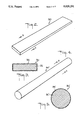
- FIG. 2 is an enlarged perspective view of a novel composite target according to the present invention as used in the electronic theft detection system of FIG. 1;
- FIG. 3 is a further enlarged section view taken along line 3--3 of FIG. 2;
- FIG. 4 is an enlarged perspective view of another form of the novel composite target according to the present invention.
- FIG. 5 is a further enlarged section view taken along line 5--5 of FIG. 4;
- FIG. 6A is a magnetic hysteresis plot of a substrate portion of the targets of FIGS. 2-5;
- FIG. 6B is a plot of the magnetic field disturbance produced by the substrate portion of the targets of FIGS. 2-5 when they are driven from magnetic saturation in one direction to magnetic saturation in the opposite direction;
- FIG. 7A is a magnetic hysteresis plot of the overall composite targets of FIGS. 2-5;
- FIG. 7B is a plot of the magnetic field disturbance produced by the overall composite targets of FIGS. 2-5 when they are driven from magnetic saturation in one direction to magnetic saturation in the opposite direction;
- FIG. 8 is a side elevational view, taken in section, of an apparatus for forming the novel targets of the present invention.
- FIG. 9 is a view taken along line 9--9 of FIG. 8;
- FIG. 10 is an enlarged view taken along line 10--10 of FIG. 8;
- FIG. 11 is a block diagram of the electronic theft detection system of FIG. 1 as configured to utilize the novel characteristics of the targets of the present invention.
- FIGS. 12a-d are timing diagrams used in explaining the operation of the electronic theft detection system as configured according to FIG. 11;
- FIG. 13 is a view similar to FIG. 1 but showing a temporarily deactivatable target assembly according to the present invention.
- FIG. 1 a theft detection system according to the present invention is shown as used in a supermarket to protect against theft of merchandise.
- a supermarket checkout counter 10 having a conveyor belt 12 which carries merchandise, such as items 14 to be purchased, (as indicated by an arrow A) past a cash register 16 positioned alongside of the counter.
- a patron who has selected goods from various shelves or bins 17 in the supermarket takes them from a shopping cart 18 and places them on the conveyor belt 12 at one end of the counter 10.
- a clerk 19 standing at the cash register 16 records the price of each item of merchandise as it moves past on the conveyor belt. The items are then paid for and are bagged at the other end of the counter.
- the theft detection system according to this invention includes a pair of spaced apart antenna panels 20 and 22 next to the counter 10 beyond the cash register 16. The antenna panels 20 and 22 are spaced far enough apart to permit the store patron and the shopping cart 18 to pass between them.
- the antenna panels 20 and 22 contain transmitter antennas which generate an alternating magnetic interrogation field in an interrogation zone 24 between the panels.
- the antenna panels 20 and 22 also contain receiver antennas (also described hereinafter) which produce electrical signals corresponding to variations in the magnetic interrogation field in the zone 24.
- the antennas are electrically connected to transmitter and receiver circuits contained in a housing 26 arranged on or near the counter 10.
- an alarm such as a light 28, mounted on the counter 10, which can easily be seen by the clerk and which is activated by the electrical circuit when a protected item 14 is carried between the antenna panels 20 and 22.
- an audible alarm may be provided instead of, or in addition to, the light 28.
- Those of the items 14 which are to be protected against shoplifting are each provided with a target 30 which comprises a thin elongated strip of a special high permeability easily saturable magnetic material according to the present invention.
- a target 30 which comprises a thin elongated strip of a special high permeability easily saturable magnetic material according to the present invention.
- the target 30 When an item 14 having a sensor element or target 30 mounted thereon enters the interrogation zone 24, it becomes exposed to the alternating magnetic interrogation field in the zone and becomes magnetized alternately in opposite directions and driven repetitively into and out of magnetic saturation. As a result, the target 30 produces unique disturbances in the magnetic field in the interrogation zone. These unique disturbances which are in the form of alternating magnetic fields at frequencies harmonically related to that of the interrogation field, are intercepted by the receiver antenna which produces corresponding electrical signals. These electrical signals, as well as other electrical signals resulting from the various magnetic fields incident upon the receiver antenna, are processed in the receiver circuits so as to distinguish those produced by true targets from those produced by other electromagnetic disturbances. Upon completion of such processing, the true target produced signals are then used to operate the alarm light 28. Thus the clerk 19 will be informed whenever a patron may attempt to carry protected articles out of the store without being purchased.
- FIGS. 2 and 3 show the sensor element or target 30 on the items 14 in FIG. 1.
- the target 30 is in the shape of a strip or ribbon.
- the specific dimensions of the target 30 are not critical to the invention, although the target should be long in relation to its cross section.
- One of the features of the invention is that the target 30 provides easily detectable responses even when its length is less than that of conventional targets.
- the target 30 may have a length of 1.25 inches (31.8 mm) to 7 inches (17.8 cm) and cross sectional dimensions of about 0.0625 inches (1.6 mm) by 0.0013 inches (0.033 mm).
- the target 30 comprises a substrate 32 which is covered by a coating 34 of finite thickness.
- the thickness of the coating 34 is less than 0.000,001 inches (0.000025 mm). It is preferred that the coating 34 cover both sides of the substrate 32.
- the substrate 32 is a low magnetic coercivity (e.g. less than 0.1 oersteds) ferromagnetic material such as an alloy of cobalt which contains iron and boron and/or silicon.
- the following formulas are the most preferred: Co 68 .5 Fe 6 .5 Si 10 B 15 and Co 70 .5 Fe 4 .5 Si 10 B 15 .
- the first composition i.e. containing Fe 6 .5, provides the best asymmetry as will be described hereinafter.
- the second composition i.e.
- the microstructure of the substrate 32 may be either crystalline or amorphous or a combination; however to avoid excessive brittleness where the principal component is cobalt, it is preferred that the substrate have a certain amount of amorphousness.
- the coating 34 is a crystalline antiferromagnetic material which is magnetically exchange coupled with the substrate 32. It is preferred that the coating 34 be a complex compound which contains cobalt because such material is antiferromagnetic and it can be formed directly on the substrate in exchange coupled relation therewith by heating the substrate in an oxidizing atmosphere.
- the senor element or target 30 may be encased in a protective and/or decorative casing of paper or plastic (not shown); and it or the casing may be provided with suitable adhesive for securing the target to the items 14 of merchandise to be protected.
- FIGS. 4 and 5 show another sensor element or target 30' of wire-like configuration.
- This target also comprises a substrate 32' and a coating 34' of the same materials, respectively, as the substrate 32 and the coating 34 of the target 30 described above.
- FIG. 6A shows the magnetic hysteresis characteristic of the material of the target substrates 32 and 32', that is, the magnetic hysteresis they exhibit in the absence of the coating 34 and 34'.
- the abscissa in FIG. 6A represents the strength (in oersteds) and direction (positive and negative) of an externally applied magnetic field (H) directed along the length of the target substrate.
- the ordinate in FIG. 6A represents the corresponding magnetization (M) (in gauss) of the target substrate.
- the applied magnetic field H is large in the negative direction (i.e. point A)
- the resulting magnetization M is likewise maximum in the negative direction.
- the substrate material is magnetically saturated and therefore any increase in the magnitude of the applied magnetic field H in the negative direction will not further increase the magnetization M of the substrate.
- the magnetization M of the target substrate remains maximally negative, i.e. it remains negatively saturated, until the applied magnetic field H reaches a substantial magnitude in the positive direction at point B. Only at this point does any further increase in the applied magnetic field H cause the magnetization M of the target substrate to increase toward a positive value. Further increase in the applied magnetic field H results in the magnetization H of the target substrate attaining a maximum value in the positive direction at a point C.
- the target substrate is magnetically saturated and any additional increase in the magnitude of the applied magnetic field will not further increase its magnetization.
- the applied magnetic field H is changed in the negative direction
- the target substrate will remain positively saturated until the applied magnetic field is at a substantial magnitude in the negative direction (point D) whereupon further change in the negative direction of the applied magnetic field will return the target substrate magnetization to saturation in the negative direction (point A).
- the applied magnetic field changes alternately between maximum positive and negative values, it drives the target substrate alternately into and out of saturation in the positive and negative directions, following the path A, B, C, D, A, etc.
- the target substrate undergoes a large change in magnetization M only through limited portions of the change in applied magnetic field H, namely between points B and C and between points D and A. It is during these changes that the target material disturbs the applied magnetic field and produces distinctive effects which can be detected.
- the slopes of the hysteresis curve between the points B and C and between the points D and A correspond to the distinctiveness of the magnetic effects produced by the target material. That is, where the slopes are steep, the changing magnetic field produces very sudden changes in magnetization with correspondingly large values of high frequency components.
- FIG. 6B shows the magnetic field disturbance produced by the alternate magnetization of the target substrate.
- FIG. 6B is the differential of the hysteresis curve of FIG. 6A along the path A, B, C, D. It will be appreciated that as the applied magnetic field H is swept back and forth between its maximum positive and negative values, the magnetization of the target substrate material will change twice during each sweep cycle, with one change in the negative direction and the other change in the positive direction. Also, it will be noted that the hysteresis curve (FIG. 6A) is essentially symmetrical, with the slopes B-C and D-A being equally steep. Consequently, the magnetization curve of FIG. 6B shows two pulses of essentially the same shape and magnitude which occur during each sweep cycle.
- the shape or narrowness of these pulses which corresponds to the high frequency components produced by the target substrate material, and the magnitude of the pulses, both depend on the sharpness of the slope of the hysteresis curve between points B and C and between points D and A.
- ferromagnetic materials have a hysteresis characteristic which generally corresponds to that shown in FIG. 6A. However, most such materials either require a large applied magnetic field to drive them into and out of magnetic saturation or have a hysteresis characteristic with very shallow slopes.
- certain materials for example permalloy and amorphous alloys of iron, nickel and cobalt, which have a very low magnetic coercivity, i.e. less than 0.1 oersted, that can be saturated in response to very low magnitude magnetic fields and which also have fairly steep slope hysteresis characteristics; and when these materials are formed into long thin target elements they are capable of producing magnetic effects which can be distinguished from most ferromagnetic objects. Accordingly such materials have been used in the past as target elements in magnetic type theft detection systems.
- FIG. 7A shows the magnetic hysteresis characteristic of the coated sensor element or target 30 and 30' of the present invention. This characteristic is generally similar to that of FIG. 6A, with points A', B', C' and D' corresponding respectively to points A, B, C and D in FIG. 6A. However the characteristic shown in FIG. 7A has two very significant differences from that of FIG. 6A. The first difference is that the slope B'-C' in FIG. 7A is substantially more steep than the slope B-C in FIG. 6A and the second difference is that the slope D'-A' in FIG. 7A is substantially less steep than the slope D-A in FIG. 6A. As a result a very much higher magnitude and narrower pulse (with high frequency components) is produced during magnetization between points B' and C' and a very much lower magnitude and wider pulse is produced during magnetization between points D' and A'.
- both of these features provide significant improvement in the detectability of the target. Firstly, the increase in the magnitude and the accompanying increase in the high frequency components of the pulse produced along the region B'-C' results in a very distinctive signal that is easily detected. Secondly, the decrease in magnitude of the pulse produced along the region D'-A' gives the target an overall asymmetrical characteristic which is extremely rare and therefore makes it possible to detect the target with high accuracy and reliability. A detection system which makes use of these unique characteristics will be described hereinafter.
- FIGS. 8-10 The manner in which the novel sensor elements or targets 30 and 30' are made is illustrated in FIGS. 8-10.
- a box furnace 40 of ceramic or other nonferromagnetic material As shown in FIGS. 8 and 9 there is provided a box furnace 40 of ceramic or other nonferromagnetic material.
- the furnace 40 contains an electrical heating element (not shown) which is capable of heating the interior of the furnace uniformly to a temperature of 260°-420° C.
- a thermocouple 42 is positioned in the furnace to monitor the temperature and the thermocouple output is connected to a conventional regulator which adjusts the heat input to the furnace accordingly.
- the specimen organizer 44 is formed with a plurality of parallel holes 46 which extend through the organizer from one side thereof to the opposite side.
- the diameter of the holes should be large enough to accommodate target strips and to permit gases to flow freely around the strips while they are being heated in the furnace.
- the holes 46 each have a diameter of about 0.30 inches (0.8 cm).
- a Permalloy tube 48 is inserted into each of the holes 46 and a non-metallic tube 50 is inserted into each of the permalloy tubes 48.
- a target substrate 32 or 32' is positioned inside each of the tubes 50.
- the furnace 40 is provided with means (not shown) to maintain a continuous supply of gas flowing therethrough and particularly through the tubes 50 in the specimen organizer 44.
- the gas should be air, pure oxygen or a mixture of argon and oxygen which will oxidize the surface of the target substrates 32 or 32' located in the tubes 50.
- the furnace 40 is positioned between a pair of Helmholtz coils 52 which produce a very precisely controlled low magnetic field in a direction perpendicular to their surfaces.
- the furnace is oriented so that the target substrates 32 and 32' extend in the direction of the magnetic field produced by the Helmholtz coils 52.
- a substrate of a cobalt alloy such as described above is positioned inside each of the tubes 50 in the specimen organizer 44 and the specimen organizer is positioned in the furnace 40.
- the furnace is then heated to a temperature of 260°-420° C. for a period of two hours to eighty hours, until a film forms on the substrate.
- the precise time and temperature will depend on the composition of the substrate material.
- the substrate should be oxidized in air at a temperature of 380° C. for twenty hours.
- the Helmholtz coils 52 are energized to produce a magnetic field of about 0.3 oersteds along the length of the oxidized target substrates. This magnetic field is maintained until the furnace is cooled down to below the Neel temperature (i.e. the temperature below which antiferromagnetism occurs in the coating). The targets may then be removed from the furnace 40. These targets will then possess the asymmetrical hysteresis characteristic shown in FIG. 7A.
- the Permalloy tubes 48 serve to isolate the target substrates from the effects of external magnetic fields (including the Earth's magnetic field) other than those produced by the Helmholtz coils, so that the magnetic bias imposed on the targets as they are cooled down to below the Neel temperature can be carefully maintained both as to magnitude and as to direction.
- FIG. 11 shows, in block diagram form, modifications which could be made to a detection system of the type shown in U.S. Pat. No. 4,623,877 which enable the system to utilize the unique asymmetric hysteresis characteristic of the novel targets of the present invention and provide even better discrimination over magnetic objects that may be present in the vicinity of the detection system.
- an oscillator 60 which is connected through a frequency divider 62 to an amplifier and driver 64 which energizes the interrogation antenna 20 at a precise frequency according to a sine wave pattern.
- the receiver antenna 22 in turn, is connected to a signal processor 66 which contains receiver filters, amplifiers and signal threshold detectors.
- the signals which are output from the signal processor 66 are applied to each of three gates 68, 70 and 72.
- the gate outputs in turn are applied to associated signal accumulators or counters 74, 76 and 78.
- the outputs of the accumulators or counters 74 and 76 are passed through associated output gates 80 and 82 and from there through an OR circuit 84 to an alarm 86.
- the gates 68, 70 and 72 are controlled by outputs from a gate control signal generator 61 which in turn receives signals from the oscillator 60.
- the gates 68 70 and 72 are opened and closed in synchronism with the interrogation field generated by the interrogation antenna 20.
- the outputs of the accumulator or counter 74 are applied to disable terminals 80a and 82a of the output gates 80 and 82, respectively.
- FIGS. 12a-12d illustrate the operation of the arrangement shown in FIG. 11 for selectively detecting the targets 30 and 30' having asymmetrical hysteresis characteristics.
- FIG. 12a represents the magnetic field intensity generated by the interrogation antenna 20 and incident on the target 30.
- FIG. 12b shows the intervals in which the gate 68 is open to pass signals.
- FIG. 12c shows the intervals in which the gate 70 is open to pass signals and
- FIG. 12d shows the intervals in which the gate 72 is open to pass signals.
- the gate 68 is open during each interval in which the applied magnetic field changes from positive to negative and vice versa. It is during these intervals that the magnetic saturation of the target material should be reversed by the changing interrogation field to produce detectable pulses.
- the gate 68 is not open to pass such signals.
- the precise timing of the open intervals of the gate 68 might be shifted somewhat but basically it should be open each time the target 30 or 30' produces a pulse signal.
- the gate 68 is open each time the magnetic interrogation field shifts from positive to negative and from negative to positive. Thus, the gate 68 is open twice during each cycle of the interrogation signal.
- the gates 70 and 72 are set to be open only once during each cycle of the interrogation signal. The gate 70 is open each time the interrogation signal changes from negative to positive and the gate 72 is open each time the interrogation signal changes from positive to negative.
- a magnetizable element having the hysteresis characteristic shown in FIG. 6A passes between the antennas 20 and 22 it will produce signals during each of the intervals when gates 68, 70 and 72 are open.
- the outputs from the gates 70 and 72 will build up or accumulate in their respective accumulators or counters 76 and 78; however, because the gate 68 is open more often in the same time, its outputs will accumulate faster in its associated accumulator or counter 74 and therefore the output from the accumulator or counter 74 will disable the gates 80 and 82 to prevent detection of the magnetic material having a symmetric hysteresis characteristic.
- a target 30 or 30' of the present invention passing between the interrogation and receiver antennas 20 and 22, it will cause detectable signals to be produced only once during each cycle of the interrogation field, either while the field is changing from positive to negative or while the field is changing from negative to positive, depending on the target orientation. If those signals are generated only while the magnetic interrogation field is changing from positive to negative, they will not pass through the gate 70 but they will pass through the gate 72. Such signals will also pass through the gate 74 but inasmuch as these signals occur only once during each cycle the output from the gate 74 is no greater than the output from the gate 72.
- the disable terminals 80a and 82a on the output gates 80 and 82 are set to close their respective gate only when the signal they receive from the accumulators or counters 74 and 76 is appreciably greater than the signals applied to the output gates 80 and 82 from the accumulators or counters 76 and 78.
- a target having an asymmetric hysteresis characteristic passes between the antennas 20 and 22, it will be detected irrespective of its orientation.
- an element having a symmetric hysteresis characteristic passes between the antennas it will not be detected.
- the present invention provides a sensor element, for example, a theft detection target, which responds to applied interrogation fields by producing narrow, high amplitude pulses which have strong high frequency components, particularly in the range of the twentieth harmonic of the interrogation field frequency.
- a sensor element for example, a theft detection target
- Such pulses are unique and easily detectable and this alone provides a substantial advantage over the prior art.
- the targets 30 and 30' can be detected in conventional magnetic type detection systems without modification, except possibly raising of the detection level threshold to further minimize false alarms.
- the targets 30 and 30' of the present invention have asymmetric hysteresis characteristics which enable them to respond to an applied alternating interrogation field by producing only one pulse during each cycle of the field or one pulse which is substantially greater (e.g. three times greater) than the other pulse produced in the same cycle.
- This provides an additional unique characteristic which, as described, permits even more reliable detection when the detection system is set, for example, as in FIG. 11, to detect only one pulse per cycle of the interrogating magnetic field.
- the asymmetrical hysteresis characteristic of the targets 30 and 30' can be temporarily cancelled by subjecting them to a magnetic bias field of between 3 and 100 oersteds and preferably from 10 to 20 oersteds.
- a magnetic bias field of between 3 and 100 oersteds and preferably from 10 to 20 oersteds.
- the targets are subjected to such a field their hysteresis characteristic is symmetrical, but when this bias field is removed the asymmetrical hysteresis characteristic is recovered.
- the target is subjected to a strong magnetic bias field, for example, greater that 100 oersteds, the asymmetric hysteresis characteristic of the target becomes permanently destroyed; and when the bias field is removed, the target retains a symmetrical hysteresis characteristic.
- FIG. 13 shows a target assembly 90 which can be temporarily deactivated so that it will not be detected by a system, such as that shown in FIG. 11, which responds only to targets having an asymmetrical hysteresis characteristic.
- the target assembly 90 comprises the target 30 of FIG. 2 and at least one deactivation element 92 of a magnetic material having a magnetic coercivity such that it can be semi-permanently magnetized and when so magnetized will impose a magnetic bias field of about 10 to 20 oersteds on the target 30.
- the deactivation element 92 When the deactivation element 92 is not magnetized, it has no effect on the target 30. Consequently, the target will retain its asymmetric hysteresis characteristic and will be detectable in the system of FIG. 11.
- the deactivation element 92 When the deactivation element 92 is magnetized, it will impose a magnetic bias on the target 30 and change its hysteresis characteristic so that it becomes symmetrical and the target assembly 90 cannot
- this bias field of 10-20 oersteds is far less than the bias field needed to deactivate prior art targets, which is normally well in excess of 60 oersteds.
- the targets 30 or 30' are provided with deactivation elements which impose such a high magnetic bias, the targets will be deactivated so as not to be detectable either by a system such as that of FIG. 11 or by a prior art detection system.
- the target 30 or 30' need not be provided with a deactivation element. Instead, such permanent deactivation can be obtained simply by exposing the target to a magnetic bias field in excess of 100 oersteds.
Abstract
Description
Claims (41)
Priority Applications (11)
| Application Number | Priority Date | Filing Date | Title |
|---|---|---|---|
| US07/506,775 US5029291A (en) | 1990-04-10 | 1990-04-10 | Electromagnetic sensor element and methods and apparatus for making and using same |
| CA002039989A CA2039989C (en) | 1990-04-10 | 1991-04-08 | Electromagnetic sensor element and methods and apparatus for making and using same |
| EP91105680A EP0451812B1 (en) | 1990-04-10 | 1991-04-10 | Electromagnetic sensor element and method for making same |
| DE69132295T DE69132295D1 (en) | 1990-04-10 | 1991-04-10 | Process and device for the production and use of magnetic security tags |
| DE69121621T DE69121621T2 (en) | 1990-04-10 | 1991-04-10 | Security tag and method of making the same |
| BR919101430A BR9101430A (en) | 1990-04-10 | 1991-04-10 | SENSOR, ARTICLE SUPERVISION SYSTEM, SENSOR MANUFACTURING PROCESS AND PROCESS TO DETECT THE PRESENCE OF A SENSOR INTERROGATION AREA |
| EP95117726A EP0701235B1 (en) | 1990-04-10 | 1991-04-10 | Use of electromagnetic sensor element in surveillance system |
| JP3077887A JPH04225504A (en) | 1990-04-10 | 1991-04-10 | Sensor device and manufacture thereof and application method and device thereof |
| EP95117727A EP0696786B1 (en) | 1990-04-10 | 1991-04-10 | Electromagnetic sensor element and method and apparatus for making and using same |
| DE69132747T DE69132747D1 (en) | 1990-04-10 | 1991-04-10 | Use of magnetic security tags |
| DE199191105680T DE451812T1 (en) | 1990-04-10 | 1991-04-10 | METHOD AND DEVICE FOR THE PRODUCTION AND USE OF MAGNETIC SECURITY LABELS. |
Applications Claiming Priority (1)
| Application Number | Priority Date | Filing Date | Title |
|---|---|---|---|
| US07/506,775 US5029291A (en) | 1990-04-10 | 1990-04-10 | Electromagnetic sensor element and methods and apparatus for making and using same |
Publications (1)
| Publication Number | Publication Date |
|---|---|
| US5029291A true US5029291A (en) | 1991-07-02 |
Family
ID=24015965
Family Applications (1)
| Application Number | Title | Priority Date | Filing Date |
|---|---|---|---|
| US07/506,775 Expired - Lifetime US5029291A (en) | 1990-04-10 | 1990-04-10 | Electromagnetic sensor element and methods and apparatus for making and using same |
Country Status (6)
| Country | Link |
|---|---|
| US (1) | US5029291A (en) |
| EP (3) | EP0451812B1 (en) |
| JP (1) | JPH04225504A (en) |
| BR (1) | BR9101430A (en) |
| CA (1) | CA2039989C (en) |
| DE (4) | DE69121621T2 (en) |
Cited By (24)
| Publication number | Priority date | Publication date | Assignee | Title |
|---|---|---|---|---|
| US5146204A (en) * | 1990-03-13 | 1992-09-08 | Knogo Corporation | Theft detection apparatus and flattened wire target and method of making same |
| EP0545422A1 (en) * | 1991-12-04 | 1993-06-09 | Knogo Corporation | Multiple pulse responder and detection system and method of making and using same |
| US5313192A (en) * | 1992-07-02 | 1994-05-17 | Sensormatic Electronics Corp. | Deactivatable/reactivatable magnetic marker having a step change in magnetic flux |
| NL9300283A (en) * | 1993-02-12 | 1994-09-01 | Kema Nv | Sealing system for an object, and a seal for that. |
| US5376923A (en) * | 1992-12-14 | 1994-12-27 | Minnesota Mining And Manufacturing Company | On the counter deactivator |
| US5410296A (en) * | 1992-10-06 | 1995-04-25 | Minnesota Mining And Manufacturing Company | Magnetic tag deactivator for pre-existing check-out counters |
| WO1995018430A1 (en) * | 1993-12-30 | 1995-07-06 | Sensormatic Electronics Corporation | Article detection in a limited interrogation zone |
| US5532598A (en) * | 1994-05-25 | 1996-07-02 | Westinghouse Electric Corporation | Amorphous metal tagging system for underground structures including elongated particles of amorphous metal embedded in nonmagnetic and nonconductive material |
| US5541577A (en) * | 1995-05-26 | 1996-07-30 | Consolidated Graphic Materials, Inc. | Electromagnetic asset protection system |
| WO1997000506A1 (en) * | 1995-06-15 | 1997-01-03 | Alliedsignal Inc. | Method of achieving a controlled step change in the magnetization loop of amorphous alloys |
| US5602528A (en) * | 1995-06-20 | 1997-02-11 | Marian Rubber Products Company, Inc. | Theft detection marker and method |
| US5602527A (en) * | 1995-02-23 | 1997-02-11 | Dainippon Ink & Chemicals Incorporated | Magnetic marker for use in identification systems and an indentification system using such magnetic marker |
| US5801630A (en) * | 1996-11-08 | 1998-09-01 | Sensormatic Electronics Corporation | Article surveillance magnetic marker having an hysteresis loop with large barkhausen discontinuities at a low field threshold level |
| US5808549A (en) * | 1995-05-17 | 1998-09-15 | Korea Institute Of Science And Technology | Magnetic sensor element and method of manufacturing the same |
| US5847650A (en) * | 1996-10-04 | 1998-12-08 | Knogo North America Inc. | Theft resistant circuit assembly |
| US5990791A (en) * | 1997-10-22 | 1999-11-23 | William B. Spargur | Anti-theft detection system |
| US6162550A (en) * | 1994-03-11 | 2000-12-19 | P. P. Payne Limited | Tagging material |
| US6169481B1 (en) * | 1999-04-12 | 2001-01-02 | Rockwell Technologies, Llc | Low cost material suitable for remote sensing |
| US6447294B1 (en) * | 1999-12-13 | 2002-09-10 | William Raymond Price | Locator for lost dentures |
| US6472987B1 (en) * | 2000-07-14 | 2002-10-29 | Massachusetts Institute Of Technology | Wireless monitoring and identification using spatially inhomogeneous structures |
| US6681989B2 (en) * | 2002-01-15 | 2004-01-27 | International Business Machines Corporation | Inventory control and point-of-sale system and method |
| US6817536B1 (en) * | 1999-08-06 | 2004-11-16 | Flying Null Limited | Coded label information extraction method |
| US6998835B1 (en) | 2002-11-20 | 2006-02-14 | The United States Of America As Represented By The Secretary Of The Navy | Electromagnetic sensor system and method |
| US7389918B2 (en) * | 2001-10-23 | 2008-06-24 | Ncr Corporation | Automatic electronic article surveillance for self-checkout |
Families Citing this family (2)
| Publication number | Priority date | Publication date | Assignee | Title |
|---|---|---|---|---|
| US5428346A (en) * | 1993-05-28 | 1995-06-27 | Sealed Air Corporation | Theft alarm activating absorbent pad |
| US5401584A (en) * | 1993-09-10 | 1995-03-28 | Knogo Corporation | Surveillance marker and method of making same |
Citations (6)
| Publication number | Priority date | Publication date | Assignee | Title |
|---|---|---|---|---|
| US2988466A (en) * | 1957-11-29 | 1961-06-13 | Gen Electric | Magnetic material |
| US4326198A (en) * | 1976-08-18 | 1982-04-20 | Knogo Corporation | Method and apparatus for the promotion of selected harmonic response signals in an article detection system |
| US4623877A (en) * | 1983-06-30 | 1986-11-18 | Knogo Corporation | Method and apparatus for detection of targets in an interrogation zone |
| US4660025A (en) * | 1984-11-26 | 1987-04-21 | Sensormatic Electronics Corporation | Article surveillance magnetic marker having an hysteresis loop with large Barkhausen discontinuities |
| US4800457A (en) * | 1987-09-29 | 1989-01-24 | Carnegie-Mellon University | Magnetoresistive sensor element |
| US4945339A (en) * | 1987-11-17 | 1990-07-31 | Hitachi Metals, Ltd. | Anti-theft sensor marker |
Family Cites Families (10)
| Publication number | Priority date | Publication date | Assignee | Title |
|---|---|---|---|---|
| DE2365178C2 (en) * | 1973-12-29 | 1982-07-01 | Basf Ag, 6700 Ludwigshafen | Process for the production of magnetic materials with exchange anisotropy behavior |
| US4384281A (en) * | 1980-10-31 | 1983-05-17 | Knogo Corporation | Theft detection apparatus using saturable magnetic targets |
| EP0078401B1 (en) * | 1981-11-02 | 1985-08-07 | Allied Corporation | Amorphous antipilferage marker |
| US4686516A (en) * | 1984-11-26 | 1987-08-11 | Sensormatic Electronics Corporation | Method, system and apparatus for use in article surveillance |
| JPH079057B2 (en) * | 1985-04-26 | 1995-02-01 | 株式会社東芝 | Amorphous alloy magnetic core manufacturing method |
| US4682154A (en) * | 1986-02-12 | 1987-07-21 | E.A.S. Technologies, Inc. | Label for use in anti-theft surveillance system |
| US4980670A (en) * | 1987-11-04 | 1990-12-25 | Sensormatic Electronics Corporation | Deactivatable E.A.S. marker having a step change in magnetic flux |
| US4809109A (en) * | 1988-03-25 | 1989-02-28 | International Business Machines Corporation | Magnetoresistive read transducer and method for making the improved transducer |
| DE3824075A1 (en) * | 1988-07-15 | 1990-01-18 | Vacuumschmelze Gmbh | COMPOSITE BODY FOR GENERATING VOLTAGE PULSES |
| FR2648942B1 (en) * | 1989-06-27 | 1995-08-11 | Thomson Csf | SENSOR WITH MAGNETORESISTIVE EFFECT |
-
1990
- 1990-04-10 US US07/506,775 patent/US5029291A/en not_active Expired - Lifetime
-
1991
- 1991-04-08 CA CA002039989A patent/CA2039989C/en not_active Expired - Fee Related
- 1991-04-10 JP JP3077887A patent/JPH04225504A/en active Pending
- 1991-04-10 DE DE69121621T patent/DE69121621T2/en not_active Expired - Fee Related
- 1991-04-10 DE DE69132747T patent/DE69132747D1/en not_active Expired - Lifetime
- 1991-04-10 BR BR919101430A patent/BR9101430A/en not_active Application Discontinuation
- 1991-04-10 EP EP91105680A patent/EP0451812B1/en not_active Expired - Lifetime
- 1991-04-10 DE DE69132295T patent/DE69132295D1/en not_active Expired - Lifetime
- 1991-04-10 EP EP95117726A patent/EP0701235B1/en not_active Expired - Lifetime
- 1991-04-10 EP EP95117727A patent/EP0696786B1/en not_active Expired - Lifetime
- 1991-04-10 DE DE199191105680T patent/DE451812T1/en active Pending
Patent Citations (6)
| Publication number | Priority date | Publication date | Assignee | Title |
|---|---|---|---|---|
| US2988466A (en) * | 1957-11-29 | 1961-06-13 | Gen Electric | Magnetic material |
| US4326198A (en) * | 1976-08-18 | 1982-04-20 | Knogo Corporation | Method and apparatus for the promotion of selected harmonic response signals in an article detection system |
| US4623877A (en) * | 1983-06-30 | 1986-11-18 | Knogo Corporation | Method and apparatus for detection of targets in an interrogation zone |
| US4660025A (en) * | 1984-11-26 | 1987-04-21 | Sensormatic Electronics Corporation | Article surveillance magnetic marker having an hysteresis loop with large Barkhausen discontinuities |
| US4800457A (en) * | 1987-09-29 | 1989-01-24 | Carnegie-Mellon University | Magnetoresistive sensor element |
| US4945339A (en) * | 1987-11-17 | 1990-07-31 | Hitachi Metals, Ltd. | Anti-theft sensor marker |
Non-Patent Citations (5)
| Title |
|---|
| Exchange Anisotropy, 1977, pp. 43 45 Permanent Magnets. * |
| Exchange Anisotropy, 1977, pp. 43-45 Permanent Magnets. |
| Meiklejohn, et al., "New Magnetic Anisotropy" Jun. 1, 1956, pp. 1413-1414 Physical review, vol. 102, No. 5. |
| Meiklejohn, et al., New Magnetic Anisotropy Jun. 1, 1956, pp. 1413 1414 Physical Review, vol. 102, No. 5. * |
| Wing Kei Ho, et al., Anisotropy Pinning of Domain Walls in Soft Magnetic Material, 8/1989 IEEE. * |
Cited By (30)
| Publication number | Priority date | Publication date | Assignee | Title |
|---|---|---|---|---|
| US5146204A (en) * | 1990-03-13 | 1992-09-08 | Knogo Corporation | Theft detection apparatus and flattened wire target and method of making same |
| AU657811B2 (en) * | 1991-12-04 | 1995-03-23 | Knogo Corporation | A method of making or detecting a responder |
| EP0545422A1 (en) * | 1991-12-04 | 1993-06-09 | Knogo Corporation | Multiple pulse responder and detection system and method of making and using same |
| US5304983A (en) * | 1991-12-04 | 1994-04-19 | Knogo Corporation | Multiple pulse responder and detection system and method of making and using same |
| US5313192A (en) * | 1992-07-02 | 1994-05-17 | Sensormatic Electronics Corp. | Deactivatable/reactivatable magnetic marker having a step change in magnetic flux |
| US5410296A (en) * | 1992-10-06 | 1995-04-25 | Minnesota Mining And Manufacturing Company | Magnetic tag deactivator for pre-existing check-out counters |
| US5376923A (en) * | 1992-12-14 | 1994-12-27 | Minnesota Mining And Manufacturing Company | On the counter deactivator |
| NL9300283A (en) * | 1993-02-12 | 1994-09-01 | Kema Nv | Sealing system for an object, and a seal for that. |
| US5422627A (en) * | 1993-02-12 | 1995-06-06 | N.V. Kema | Sealing system for an object and seal therefor |
| WO1995018430A1 (en) * | 1993-12-30 | 1995-07-06 | Sensormatic Electronics Corporation | Article detection in a limited interrogation zone |
| US6627031B1 (en) | 1994-03-11 | 2003-09-30 | P. P. Payne Limited | Tagging material method and means for applying tagging material |
| US6162550A (en) * | 1994-03-11 | 2000-12-19 | P. P. Payne Limited | Tagging material |
| US5532598A (en) * | 1994-05-25 | 1996-07-02 | Westinghouse Electric Corporation | Amorphous metal tagging system for underground structures including elongated particles of amorphous metal embedded in nonmagnetic and nonconductive material |
| US5602527A (en) * | 1995-02-23 | 1997-02-11 | Dainippon Ink & Chemicals Incorporated | Magnetic marker for use in identification systems and an indentification system using such magnetic marker |
| US5808549A (en) * | 1995-05-17 | 1998-09-15 | Korea Institute Of Science And Technology | Magnetic sensor element and method of manufacturing the same |
| US5541577A (en) * | 1995-05-26 | 1996-07-30 | Consolidated Graphic Materials, Inc. | Electromagnetic asset protection system |
| US5800635A (en) * | 1995-06-15 | 1998-09-01 | Alliedsignal Inc. | Method of achieving a controlled step change in the magnetization loop of amorphous alloys |
| WO1997000506A1 (en) * | 1995-06-15 | 1997-01-03 | Alliedsignal Inc. | Method of achieving a controlled step change in the magnetization loop of amorphous alloys |
| US5602528A (en) * | 1995-06-20 | 1997-02-11 | Marian Rubber Products Company, Inc. | Theft detection marker and method |
| US5847650A (en) * | 1996-10-04 | 1998-12-08 | Knogo North America Inc. | Theft resistant circuit assembly |
| US5801630A (en) * | 1996-11-08 | 1998-09-01 | Sensormatic Electronics Corporation | Article surveillance magnetic marker having an hysteresis loop with large barkhausen discontinuities at a low field threshold level |
| US5990791A (en) * | 1997-10-22 | 1999-11-23 | William B. Spargur | Anti-theft detection system |
| US6169481B1 (en) * | 1999-04-12 | 2001-01-02 | Rockwell Technologies, Llc | Low cost material suitable for remote sensing |
| US6817536B1 (en) * | 1999-08-06 | 2004-11-16 | Flying Null Limited | Coded label information extraction method |
| US6447294B1 (en) * | 1999-12-13 | 2002-09-10 | William Raymond Price | Locator for lost dentures |
| US6693540B2 (en) | 2000-07-14 | 2004-02-17 | Massachusetts Institute Of Technology | Wireless monitoring and identification using spatially inhomogeneous structures |
| US6472987B1 (en) * | 2000-07-14 | 2002-10-29 | Massachusetts Institute Of Technology | Wireless monitoring and identification using spatially inhomogeneous structures |
| US7389918B2 (en) * | 2001-10-23 | 2008-06-24 | Ncr Corporation | Automatic electronic article surveillance for self-checkout |
| US6681989B2 (en) * | 2002-01-15 | 2004-01-27 | International Business Machines Corporation | Inventory control and point-of-sale system and method |
| US6998835B1 (en) | 2002-11-20 | 2006-02-14 | The United States Of America As Represented By The Secretary Of The Navy | Electromagnetic sensor system and method |
Also Published As
| Publication number | Publication date |
|---|---|
| EP0696786B1 (en) | 2000-07-05 |
| EP0696786A3 (en) | 1996-11-06 |
| JPH04225504A (en) | 1992-08-14 |
| EP0701235A2 (en) | 1996-03-13 |
| DE451812T1 (en) | 1992-04-09 |
| EP0451812B1 (en) | 1996-08-28 |
| BR9101430A (en) | 1991-11-26 |
| CA2039989A1 (en) | 1991-10-11 |
| EP0451812A3 (en) | 1991-12-18 |
| EP0701235B1 (en) | 2001-09-26 |
| DE69121621D1 (en) | 1996-10-02 |
| EP0701235A3 (en) | 1996-11-13 |
| EP0451812A2 (en) | 1991-10-16 |
| DE69121621T2 (en) | 1997-04-03 |
| DE69132295D1 (en) | 2000-08-10 |
| DE69132747D1 (en) | 2001-10-31 |
| EP0696786A2 (en) | 1996-02-14 |
| CA2039989C (en) | 1994-11-08 |
Similar Documents
| Publication | Publication Date | Title |
|---|---|---|
| US5029291A (en) | Electromagnetic sensor element and methods and apparatus for making and using same | |
| US4510489A (en) | Surveillance system having magnetomechanical marker | |
| JP2666812B2 (en) | Amorphous anti-theft marker | |
| CA1200872A (en) | Coded surveillance system having magnetomechanical marker | |
| US4510490A (en) | Coded surveillance system having magnetomechanical marker | |
| US4622543A (en) | Surveillance system having acoustic magnetomechanical marker | |
| US5729201A (en) | Identification tags using amorphous wire | |
| US5146204A (en) | Theft detection apparatus and flattened wire target and method of making same | |
| EP1066612B1 (en) | Redistributing magnetic charge in bias element for magnetomechanical eas marker | |
| JPS5886694A (en) | Amorphous burglarproof marker | |
| US5304983A (en) | Multiple pulse responder and detection system and method of making and using same | |
| US20080143533A1 (en) | Magnetoacoustic markers based on magnetic microwire, and method of obtaining the same | |
| KR20010030740A (en) | Metallic glass alloys for mechanically resonant marker surveillance systems | |
| JP2892995B2 (en) | Magnetic sensor element, method of manufacturing the same, and anti-theft system equipped with the magnetic sensor element | |
| EP0604293A1 (en) | Dual status thin-film EAS marker | |
| KR0163822B1 (en) | Magnetic sensor and system for preventing stealth | |
| Graham et al. | APPLICATIONS OF ASYMMETRIC HYSTERESIS LOOPS IN AMORPHOUS ALLOYS | |
| JPH01131994A (en) | Marker for burglar sensor |
Legal Events
| Date | Code | Title | Description |
|---|---|---|---|
| AS | Assignment |
Owner name: KNOGO CORPORATION, NEW YORK Free format text: ASSIGNMENT OF ASSIGNORS INTEREST.;ASSIGNOR:COOPER, MICHAEL N.;REEL/FRAME:005288/0917 Effective date: 19900408 Owner name: KNOGO CORPORATION, NEW YORK Free format text: ASSIGNMENT OF ASSIGNORS INTEREST.;ASSIGNORS:ZHOU, Y. PETER;SHIN, KYUNG-HO;SOLASKI, THOMAS P.;AND OTHERS;REEL/FRAME:005288/0913 Effective date: 19900409 |
|
| STCF | Information on status: patent grant |
Free format text: PATENTED CASE |
|
| CC | Certificate of correction | ||
| FPAY | Fee payment |
Year of fee payment: 4 |
|
| AS | Assignment |
Owner name: KNOGO NORTH AMERICA INC., NEW YORK Free format text: ASSIGNMENT OF ASSIGNORS INTEREST;ASSIGNOR:KNOGO CORPORATION;REEL/FRAME:007317/0220 Effective date: 19941227 |
|
| FEPP | Fee payment procedure |
Free format text: PAT HOLDER CLAIMS SMALL ENTITY STATUS - SMALL BUSINESS (ORIGINAL EVENT CODE: SM02); ENTITY STATUS OF PATENT OWNER: SMALL ENTITY Free format text: PAYOR NUMBER ASSIGNED (ORIGINAL EVENT CODE: ASPN); ENTITY STATUS OF PATENT OWNER: SMALL ENTITY Free format text: PAYER NUMBER DE-ASSIGNED (ORIGINAL EVENT CODE: RMPN); ENTITY STATUS OF PATENT OWNER: SMALL ENTITY |
|
| AS | Assignment |
Owner name: GENERAL ELECTRIC CAPITAL CORPORATION, CONNECTICUT Free format text: SECURITY AGREEMENT;ASSIGNOR:KNOGO NORTH AMERICA, INC.;REEL/FRAME:008995/0730 Effective date: 19971231 |
|
| FPAY | Fee payment |
Year of fee payment: 8 |
|
| AS | Assignment |
Owner name: CIT GROUP/BUISNESS CREDIT, INC., NEW YORK Free format text: SECURITY AGREEMENT;ASSIGNOR:SENTRY TECHNOLOGY CORPORATION;REEL/FRAME:013417/0634 Effective date: 20020322 |
|
| FEPP | Fee payment procedure |
Free format text: PAYOR NUMBER ASSIGNED (ORIGINAL EVENT CODE: ASPN); ENTITY STATUS OF PATENT OWNER: SMALL ENTITY Free format text: PAYER NUMBER DE-ASSIGNED (ORIGINAL EVENT CODE: RMPN); ENTITY STATUS OF PATENT OWNER: SMALL ENTITY |
|
| FPAY | Fee payment |
Year of fee payment: 12 |
|
| AS | Assignment |
Owner name: ROYAL BANK OF CANADA, CANADA Free format text: SECURITY AGREEMENT;ASSIGNOR:SENTRY TECHNOLOGY CORPORATION;REEL/FRAME:021253/0436 Effective date: 20050509 |