US5028950A - Dual stage 3D printer - Google Patents
Dual stage 3D printer Download PDFInfo
- Publication number
- US5028950A US5028950A US07/482,160 US48216090A US5028950A US 5028950 A US5028950 A US 5028950A US 48216090 A US48216090 A US 48216090A US 5028950 A US5028950 A US 5028950A
- Authority
- US
- United States
- Prior art keywords
- frame
- film
- image
- images
- Prior art date
- Legal status (The legal status is an assumption and is not a legal conclusion. Google has not performed a legal analysis and makes no representation as to the accuracy of the status listed.)
- Expired - Fee Related
Links
Images


Classifications
-
- G—PHYSICS
- G03—PHOTOGRAPHY; CINEMATOGRAPHY; ANALOGOUS TECHNIQUES USING WAVES OTHER THAN OPTICAL WAVES; ELECTROGRAPHY; HOLOGRAPHY
- G03B—APPARATUS OR ARRANGEMENTS FOR TAKING PHOTOGRAPHS OR FOR PROJECTING OR VIEWING THEM; APPARATUS OR ARRANGEMENTS EMPLOYING ANALOGOUS TECHNIQUES USING WAVES OTHER THAN OPTICAL WAVES; ACCESSORIES THEREFOR
- G03B35/00—Stereoscopic photography
- G03B35/08—Stereoscopic photography by simultaneous recording
-
- G—PHYSICS
- G03—PHOTOGRAPHY; CINEMATOGRAPHY; ANALOGOUS TECHNIQUES USING WAVES OTHER THAN OPTICAL WAVES; ELECTROGRAPHY; HOLOGRAPHY
- G03B—APPARATUS OR ARRANGEMENTS FOR TAKING PHOTOGRAPHS OR FOR PROJECTING OR VIEWING THEM; APPARATUS OR ARRANGEMENTS EMPLOYING ANALOGOUS TECHNIQUES USING WAVES OTHER THAN OPTICAL WAVES; ACCESSORIES THEREFOR
- G03B35/00—Stereoscopic photography
- G03B35/14—Printing apparatus specially adapted for conversion between different types of record
Definitions
- a plurality of two-dimensional (2D) views of a scene are recorded from a number of horizontally spaced-apart vantage points.
- the recording medium is commonly photographic film.
- the recording camera may be a single frame/single lens device with exposures made by translating the camera horizontally through a series of equally spaced vantage points from each of which the scene is photographed.
- Other techniques include photographing the scene using a multilens camera, a motion picture camera which is translated horizontally (during a short exposure burst of frames), a number of side-by-side cameras, and other commonly used methods. Having recorded the series of 2D images (normally on color negative film), it remains to combine these images into a final positive image for three-dimensional (3D) viewing.
- the method used in the present invention employs lenticular technology, in which the 2D images are recorded in a photographic emulsion that is located behind a transparent lens sheet composed of vertically oriented, adjacent cylindrical lenses (lenticules).
- Each 2D image is "line-formed" --i.e., elements of all of the 2D images are contained within fine vertical lines behind each lenticule.
- the 2D frames are sequentially projected through the lenticular sheet over a series of horizontal angular zones. When viewing the composite image, the 2D frames will "feed back" to the viewer in the same angular zones in which they were originally exposed.
- the 3D effect results solely from the difference in the horizontal displacement of points in the picture (parallax) with respect to objects in some reference plane in the two 2D frames (stereo pair) being seen by the viewer.
- the viewer's eyes and brain interpret and translate this parallax information into depth perception. Two frames and two eyes are required to complete this cycle.
- FIG. 1 A further understanding of parallax in the recorded frames can be obtained by reference to FIG. 1 where two spaced-apart lenses (L1 and L2) of equal focal length are shown imaging two points (A and B) as A' and B'.
- FIGS. 1-A 1-B, and 1-C Three arbitrary spatial locations of A and B are shown in FIGS. 1-A 1-B, and 1-C.
- a and B are placed an equal distance from the lenses with A on the optical axis of L1 and B on the optical axis of L2.
- x 1 is clearly equal to x 2 with B imaging on the same side of A from both lenses.
- x 2 is greater than x 1 , with B again recording on the other side of A.
- FIG. 1 two spaced-apart lenses (L1 and L2) of equal focal length are shown imaging two points (A and B) as A' and B'.
- FIGS. 1-A 1-B, and 1-C Three arbitrary spatial locations of A and B are shown in FIGS. 1-A 1-B, and 1-
- 1C demonstrates a location of A and B producing an x 1 greater than x 2 with B imaging on one side of A from L2 but on the other side of A from L1.
- This horizontal shift in image points as seen through lenses located in horizontally displaced vantage points will be collectively referred to as parallax.
- the number N of 2D frames employed can range from two to a larger number--e.g., 32.
- the optimum number of frames used is determined by such factors as the size of the final print, the anticipated viewing distance to the print, the spatial frequency of the cylindrical lenses in the print material, and the resolving power of the photographic emulsion.
- the larger the print and the longer the viewing distance the lower the spatial frequency of the lenticules and the greater the number of 2D frames required.
- the greater number of 2D frames is required in order to reduce the angular width of the "feedback" zone of each frame which is needed at the greater viewing distances.
- each lenticule is 0.005 inches wide. This provides a line width of 1.25 mils (32 microns) for recording a verticle element of each of the four frames as an image band in the photographic emulsion under each lenticule.
- each lens can be considered to record an infinite number of "object planes" in the scene from the nearest object and out to infinity (or to the furthest object in the scene).
- object planes In combining the 2D images into the final lenticular stereogram, a particular plane is selected to appear (to the viewer) to lie in the plane of the print. Other planes will appear to be either in front of the print plane (foreground objects) or behind the print plane (background objects). In the object plane selected to appear to lie in the plane of the print, there is normally a prominent object, which will be referred to as the "key subject.”
- the asterisk (*) in each frame (1, 2, 3 and 4) is the image of the key subject (e.g., the nose of a person standing at mid-range in the scene).
- the stereo pairs (for subsequent viewing by the right and left eye of the viewer, respectively) are 1-2, 2-3, 3-4, 1-3, or 2-4.
- Composing of the final stereogram is carried out by a printer.
- One task of the printer is to project the 2D frames across the assigned angular exposure zones to the lenticular recording material. While this may be accomplished through a series of "step and repeat" static exposures, the technique preferably used is either intermittently or continuously scanning, which is clearly explained in the patents referred to above and is also illustrated in FIG. 3. Again a set of four negative photographic images (#1, #2, #3, and #4) on a film strip is depicted as an example.
- image #4 is scanned through an angle from -15° to 71/2° by moving the film strip, the lens and the lamphouse proportionately from left to right.
- the film emulsion bears the latent images of elements of all four negative frames as side-by-side image bands under the lenticules.
- the enlarging lens images the 2D negative film frame on the surfaces of the lenticules.
- the first imaging action shown at the left as "#1 (macro)" in FIG. 4
- the enlarging lens images the 2D negative film frame on the surfaces of the lenticules.
- the enlarging lens images the 2D negative film frame on the surfaces of the lenticules.
- the lenticule (cylindrical lens) unidirectionally images the exit pupil of the enlarging lens into the focal plane of the cylindrical lens )plane of the photographic emulsion).
- This second imaging action "line-forms" a vertical element of the frame into its assigned zone behind each lenticule.
- the "object” in this second (micro) imaging action is the exit pupil of the enlarging lens.
- any small ⁇ x, ⁇ y area of a lenticle it appears as a generally diffuse, uniformly illuminated disc whose color and intensity vary as a function of the content of the aerial image as seen from the ⁇ x, ⁇ y area under consideration.
- the cylindrical lens images in only one direction (at right angles to its long axis), which produces a generally elliptical exposure profile across the width e of the line image. This results directly from the area of the disc increasing from 0 at zone 140 to a maximum at zone 141 and back to 0 at zone 142 (elliptical function).
- a second result of the unidirectional imaging is that no detail is recorded across the line width e while any detail in the aerial image down the long axis of the lenticle is preserved.
- the line width e is determined as follows (refer to the right sketch in FIG. 4):
- ⁇ is seen to be 0.93°.
- ⁇ is approximately 3% of the full acceptance angle--hence the need to scan (move the exit pupil over a range of angular positions) in order to expose 25% of W (assuming a 4-frame image set).
- the dimension e shown in the center view of FIG. 4 is 3% of 0.005" or 0.00015" (3.8 microns).
- the generally elliptical intensity within this fine line becomes essentially unimportant during the scan because of the continuously overlapping exposures it produces.
- the first function of the printer is the sequential, proportional scanning of each 2D frame through a defined angular zone resulting in the line-forming of each frame.
- a second and equally important function of the printer is the creation of the viewer illusion that the key subject plane appears to lie in the plane of the print material with foreground and background objects appearing to be in front of and behind the print plane, respectively.
- This function requires the performance of two actions by the printer and/or the printer operator: 1) The designation (typically by the operator) of the key subject which is to be presented to the viewer as lying in the plane of the print. 2) The registration by the printer of the key subject from all 2D frames at the print plane. This means that the key subject in the aerial image from each 2D frame must strike the plane of lenticular surface at the same x,y coordinate location.
- the first frame of the 2D set is picked up by a video camera and presented to the printer operator as a positive image on a video monitor.
- the operator designates the key subject (to be printed in registration) using a screen cursor controlled by a joystick, roll ball, or other controller.
- another frame of the set is analyzed for color content and density, from which the required lamphouse intensity and color and color balance are computed.
- the printing cycle is ready to begin.
- the first frame of the set is printed with no positioning correction, following which the printing is stopped to permit an operator-controlled registration cycle.
- a mirror is introduced into the printing path to deflect the aerial image to a secondary plane at 90° to the print plane.
- a CCD video camera (without a lens) is moved by an x,y stage to the coordinate location of the designated key subject.
- the key subject image is captured by the photosensitive surface of the video camera, placed in digital memory (frame grabber), and presented to the operator as a positive video image on the monitor.
- the film is then advanced to the second frame of the 2D set, which is again intercepted by the mirror and the key subject video camera and presented on the monitor as a "live" negative image.
- the operator uses a controller to move the film in the printer to bring the key subject in the second frame into registration with the "stored" location of the key subject in the first frame.
- the negative video of the second frame cancels the positive video of the stored first frame and the screen is "greyed out."
- the mirror is removed and the second frame is printed. This procedure is repeated for all remaining frames.
- the printing is seen to involve a serial operation of print, register, print, register, print, register, and print, the operator being required to perform the actual frame-to-frame registration.
- the printing time for each picture is typically 12 to 15 seconds, depending upon the skill of the operator.
- the prints-per-hour rate is in the order of 250.
- the printing is also very operator-intensive with operator fatigue being a significant negative factor.
- An optional approach used heretofore uses a complete registration cycle for all 2-D frames to be printed (again with manual frame-to-frame registration by an operator with all registration data stored digitally) after which a printing cycle is performed. Total cycle time for each print remains high--in the range of 11 to 14 seconds--again depending upon the skill and fatigue level of the operator.
- the 3D printer of the present invention employs a unique approach to color analysis and key subject registration by utilizing two stages in a functionally parallel mode--an edit station and a print station.
- the only operator action is the designation of the key subject, while the required frame-to-frame registration data are produced electronically using a sophisticated image-processing system. Total time per print is reduced to four to five seconds with far less dependence on an operator.
- the invention is a dual-stage 3D printer for forming latent line-formed photographic images on lenticular print film from a set of N frames of negative images N 1 --N n of a scene in which a selected key subject of the scene is to be formed in the developed photographic image so as to appear to a viewer to be in the plane of the print.
- image content data signals are generated periodically and frame-by-frame that are indicative of the densities of a matrix of zones of the images of each frame N 1 --N n of the set.
- the image content data signals of one of the frames N 1 are generated first and are visually displayed for selection by an operator of a key subject area of the image.
- the image content data signals for the operator-selected key subject area of frame N 1 are processed to produce identifier signals distinctly indicative of the content and location of the key subject area of frame N 1 .
- selected portions of the image content data signals for each of the other frames N 2 --N n are generated and compared seriatim by correlation with the identifier signals, and registration signals indicative of the location of the key subject area of the images of each of the frames N 2 --N n are generated and stored.
- frame N 1 is printed from a preset location, and each frame N 2 --N n is positioned automatically in response to the registration signals for the individual frames N 2 --N n , such that the key subject of each of the frames N 2 --N.sub. n is in registry in the plane of the print film with the key subject in frame N 1 .
- the image content data are generated in the edit station by sequentially projecting diffuse light through each of the frames N 1 --N n and a lens onto the photoreceptor of a CCD video camera.
- the image content data signals and identifier signals are derived from the output signals of selected arrays of pixels of the CCD camera and are indicative of the optical densities of a matrix of zones of the entire frame and a matrix of zones of the key subject area, respectively.
- the edit station may, advantageously, also include means for separately interposing red, green and blue filters in the path of the negative image of one of the frames projected to the video camera so as to provide image color data signals indicative of the densities of red, green and blue components of the images in a matrix of zones of that frame of the set and, of course, of the entire set of images.
- the image color data signals are processed and used in the print station for controlling the red, green and blue components of the imaging illumination projected into the print film.
- the frames of the negative set to be printed are, preferably, arranged closely together side by side on a film strip having a longitudinal axis x.
- the registration signals for each frame N 2 --N n include an x-axis component ⁇ x indicative of the difference along the x axis between the position of the key subject area in frame N1 and the position along the x axis of the key subject area in the respective frame N 2 --N n .
- Both the edit station and print station include a movable film gate receiving the film strip in a fixed position and a drive for moving the film gate along the x axis to advance it frame by frame in response to x-axis control signals, the x-axis control signals for moving the film gate of the print station for each frame N 2 --N n being the algebraic sum of the x-axis control signal for moving the film gate of the edit station for that frame and the x-axis component ⁇ x of the registration signals for that frame.
- Registration of the key subject area in the y-axis direction is obtained in the print station by moving the projecting lens in the y-axis direction in response to a y-axis component ⁇ y of the registration signals for each frame N 2 --N n .
- the negative images to be printed may be assembled from many film rolls spliced together to form a continuous strip, each set of 2D images being marked by a machine-readable marker located in a predetermined relation to frame N 1 of each set.
- the edit station includes a detecting device for reading the marker on the strip and producing a signal indicative of the position of frame N 1 of each set and a film advance device for advancing the film to position frame N 1 of each set in the image path from the light source to the video camera in response to detection of the marker for that set.
- the edit station and print station preferably include separate film advance devices for automatically advancing the film strip after processing of each image set.
- a slack loop station between the edit station and the print station holds a portion of the strip containing a varying number of image sets so that the print station can process prints on fully automated constant-time cycles while the edit station can operate on variable-time cycles involving operator intervention for key subject selection.
- FIGS. 1A, 1B and 1C are diagrams illustrating the concept of parallax, as described above;
- FIG. 2 is a diagram of a set of 2D photographic images taken from horizontally spaced vantage points illustrating the different location of the key subject image on each frame;
- FIGS. 3 and 4 are pictorial, schematic drawings depicting how 2D images are composed to form line-formed images on lenticular stereogram prints;
- FIG. 5 is a block diagram of the main assemblies of a printer constructed in accordance with the invention.
- FIG. 6 is a block diagram of the operator interface assembly
- FIG. 7 is a pictorial view, in generally schematic form, of the edit station of the embodiment of FIG. 5;
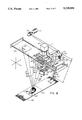
- FIG. 8 is a generally schematic pictorial view of the print station of the embodiment of FIG. 5.
- the edit station determines the lamphouse printing parameters (red, green, and blue light intensity) for each negative set to be printed and the registration data for printing each of the 2-D frames of the set with precise registration of the key subject in the plane of the print material.
- the film to be printed is generally multiple rolls of color negative film which have been spliced together, processed, and edge-notched to identify each series of frames that make up one set of 2D images to produce the stereogram print.
- This large roll of spliced film rolls is loaded on the printer at the Film Supply Assembly, and a leader (film without images) is threaded through the Edit Station, Slack Loop Assembly and Print Station and attached to an empty take-up spool on the Film Take-up Assembly.
- the film is advanced from image set to image set in the Edit Station where printing parameters and key subject registration values are automatically determined.
- the major functional components of the Edit Station are the Edit Lamphouse, Video Camera, Auto-registration Computer, and Printing Parameter Computer.
- the Slack Loop Assembly is a passive device which stores a variable number (up to 20) of image sets to be printed. (As will later become apparent, the Print Station operates fully automatically, whereas the Edit Station involves operator intervention for selection of the key subject, and the Slack Loop Assembly allows time differences between processing in the Edit Station and Print Station to be compensated for.)
- the Print Station provides for the precision proportional scanning of all 2-D images in each set.
- the Print Lamphouse is automatically adjusted to the computed (and stored) R, G, and B (red, green and blue) intensity values for each print while the Print Material Transport Assembly provides for the metered advance of the lenticular print material from a supply roll and take up onto a roll of exposed print material. All machine functions are controlled by a computer and electronics located in the Electronics Bay.
- the Operator Station (see FIG. 6) contains two video displays, a key pad, a roll ball and other controls (not shown) necessary for all operator functions.
- Video display I displays the 2D frame for operator selection of the key subject.
- Video display II presents text, menus and operator prompts.
- DX code machine readable code
- the Printer uses the DX code to identify the specific film type to be printed.
- small edge notches are punched on the edge of the film opposite the DX code. Each notch is precisely located with respect to each 4-frame image set and will be used by the printer to accurately stop the film and locate it in film gate in both the Edit and Print Stations.
- a film advance motor 2 is turned on to advance the film along the x axis using a film drive roller 17 and an opposing pressure roller 18.
- a notch detector and DX code reader 20 senses the film as it is advanced. The film identity is read and placed in digital memory. Upon detection of the locating notch, the film is advanced a previously calibrated (metered) distance and stopped precisely located in film gate 4. Advance metering following notch detection is accomplished by counting pulses from a film advance encoder 3. Not shown in FIG.
- the frame set to be edited contains images 21 through 24.
- the film gate 4, notch detector and DX code reader 20, and the film advance components 2, 3, 17, and 18 are parts of an integral unit which is mounted to a linear positioning stage (not shown) and can be positioned at any instructed position along the x axis by a stepper motor 8, a lead screw 7, and a driven nut 19, which is mechanically attached to the gate 4.
- the gate 4 is initially positioned to center the frame 21 on the system optical axis 25.
- Frame 21 is uniformly and diffusely illuminated by an edit lamphouse 1.
- the lamphouse 1, a filter wheel 9 (with path filters neutral density 10, red 11, green 12, and blue 13), lens 15, insertable neutral density filters 26 and 27, and a video camera 16 comprise a precision densitomerter that permits "point density by color” measurements of the film.
- the filter wheel 9 is rotated 90° clockwise by a stepper motor 14, placing the red filter 11 in the optical path.
- the frame 21 is imaged (through red filter 11) by the lens 15 onto the CCD photoreceptor of the video camera 16.
- the video camera 16 is calibrated to respond linearly to the illumination transmitted through the full range of expected film densities.
- a square array of 400 ⁇ 400 pixels is used for the film density calculations.
- Each pixel in the 400 ⁇ 400 array is digitized to an 8 bit number with a value of 1 to 255
- the 400 ⁇ 400 matrix is then reduced to a 10 ⁇ 10 matrix of digitized numbers in which the number for each of the 100 total film zones is the average of the 40 ⁇ 40 91600) pixels in each zone.
- a conversion is then made (through a lookup table) to a 10 ⁇ 10 matrix of density values.
- Film density is defined as the log to the base 10 of 1 over the transmission, to wit:
- T transmission
- I i light intensity in
- I o light intensity out
- D transmission density
- the full 10 ⁇ 10 matrix of red density values D 1R --D 100R ) becomes one of the inputs to the printing algorithm.
- the filter wheel 9 is rotated another 90° clockwise to place the green filter 12 in the optical path, and the above-described procedure is repeated to produce D 1G --D 100G .
- the blue filter 13 is used to produce D 1B --D 100B .
- the filter wheel 9 is advanced a final 90° to again insert neutral density filter 10 into the optical path.
- the total cycle time for gathering all density values by color for the 100 film zones is less than 1 second.
- the insertable neutral density filters 26 and 27 have density values of 0.3 and 0.6, respectively, providing the ability to add to the filter 10 0, 0.3, 0.6, or 0.9 of neutral density to the path.
- the computer now inserts additional filtration (if required) to provide the operator with an optimum image of frame 21 on TV monitor I of the operator interface (FIG. 6).
- the live video signal is also inverted to produce a positive image of the color negative frame--frame 21 (sometimes referred to herein as "frame N1”) remains in the optical path.
- the operator selects a key subject in frame N 1 that is to be printed in registration in the Print Station (i.e., made to appear in the stereogram as lying in the plane of the print and with other objects appearing to lie in front of or behind the registered plane).
- the operator uses the roll-ball control to place a square cursor (28 ⁇ 28 pixels referenced to the CCD video camera sensor) over the selected key subject in frame N 1 and presses an ENTER key.
- the Auto Registration Computer 28 "models" the density value of each pixel within the 28 ⁇ 28 key subject area and stores it in memory. This "model” will be used during the auto-registration cycle to find the x,y coordinate location of this key subject in all subsequent frames N 2 , N 3 and N 4 (22-24 in FIG. 7).
- the stepper motor 8, lead screw 7, and driver nut 19 are used to move the film gate 4 along the x axis through the nominal frame-to-frame distance to center the next frame 22 on the optical axis 25.
- the key subject in frame 22 is now normally displaced from its coordinate location in frame 21. This results from a number of factors, such as film tracking errors in the original recording camera, lens centering errors in the original recording camera (if a multilens camera is used), distance variation from the recording camera to the key subject (magnitude of recorded parallax), and the separation of the vantage points from which the 2D frames were originally recorded.
- the Auto Registration Computer now does a "correlation search" in an area 55 pixels in height (along the y axis) and 95 pixels wide (along the x axis); the 55 ⁇ 95 pixel area is centered on the coordinate location of the key subject "model” from frame 21. (If a pattern match is not found in the 55 ⁇ 95 area, the search is expanded to a 75 ⁇ 150 area.)
- the coordinate location of the key subject is found in frame 22
- its location is recorded as a plus or minus deviation along both the x and y axis ( ⁇ x2, ⁇ y2) from its location in frame 21.
- the system has the ability to resolve the coordinate location within 1/5 pixel spacing--i.e., approximately 1/2500 of the frame width.
- the coordinate deviation values are converted from pixel units to stepper motor steps prior to storing the values for subsequent use in the Print Station.
- the full sequence of events (advance film, search, and store) is repeated to obtain registration data for frames 23 and 24. No operator interaction is required beyond the initial selection of the key subject.
- the computation of the printing parameters is initiated and completed during the auto registration cycle by the Printing Parameter Computer 29, based on the image color content data produced by the Edit Station. Knowing the location of the key subject in the picture, a color algorithm "weights" the density values in this area more heavily than other areas of the image in determining the optimum output for the printing lamphouse. In this respect the printer applies technology that is used in all modern computerized color printers to determine the amount of color and light required to expose the negative onto color print paper.
- the algorithm is a series of equations that corrects the color and density of the negative into either red, green, and blue printing times (exposure light level constant) or red, green, and blue light levels (time constant). As is known per se.
- the algorithm weights certain parts of the negative, such as the center and the lower right and left quadrants, more heavily than other areas.
- image content data are available for use in the printer in the form of a matrix of "area density by color" values coupled with the knowledge of which area contains the key subject of the picture.
- the key subject is often a person in the picture whose printing at optimum density and color balance are of prime importance to maximize the yield of superior printed images.
- the full array of algorithm inputs consists of 100 area density values using red light (density matrix of the cyan emulsion dye), 100 area density values using green light (density matrix of the magenta emulsion dye), 100 area density values using blue light (density matrix of the yellow emulsion dye), the DX code identifying the film type, and the x,y, coordinate location of the key subject.
- the algorithm manipulates this data to produce the three outputs shown (FIG. 7) as R (red), G (Green), and B (Blue).
- These three outputs specify the red, green, and blue light intensity levels required from the printing lamphouse for optimum exposure of the print, and are stored in computer memory until the image set arrives at the Print Station, at which time a closed loop servo system sets color filtration in the lamphouse to these specified values.
- the mechanism for advancing the film and holding it in a known position during the printing cycle is identical to the mechanism used in the Edit Station.
- Components 102, 103, 104, 105, 106, 107 and 108 are physically and functionally the same as the components 2, 3, 4, 5, 6, 7 and 8 of the Edit Station.
- the film gate 104 and its x-axis translating components (linear stage 142, lead screw 107, and stepper motor 108 are all mounted on a second x-axis translating carriage, the scan carriage 109.
- the scan carriage 109 (mounted on a linear stage 110) is positioned along the x axis by a cable 111, drum 112, and scan motor 113.
- the enlarging lens 140 is mounted on a plate 117 which is attached to a lens carriage 116 via a y-axis stage 141.
- the lens is positioned along the y axis by a lead screw 114 and a stepper motor 115.
- a lens carriage 116 moves along the x axis also using the linear stage 110.
- the lens carriage 116 is moved along the x axis by a proportioning arm 118, which is coupled to the scan carriage 109 (and hence indirectly to the film gate 104), the lens carriage 116, and to a fixed pivot point 119.
- a block 132 and a pivot shaft 133 permit the proportioning arm 118 to rotate freely in a plane defined by the axes x and z.
- the block 132 is attached to the scan carriage 109.
- a second pivot shaft 120 is connected to the lens carriage 116 by a block 134.
- a slot 135 permits the pivot shaft 120 to slide along the axis of proportioning arm 118 as the scan carriage 109 moves along the x axis.
- a third pivot shaft 119 is attached to a block 137 which is mounted in a fixed x-, y-axis coordinate location but is adjustable along the z axis.
- a slot 136 performs the same function as the slot 135.
- the distance from the pivot 133 to the pivot 120 (labeled B) and the distance from the pivot 120 to the pivot 119 (labelled A) are continuously changing as the scan carriage 109 moves along the x axis, but the ratio of A to B (A/B) remains constant. This ratio is adjusted so that A/B is equal to the optical enlargement ratio of the printer.
- the enlarging lens 140 is a distortion-free design so that the enlarging ratio remains constant at any position of the scan carriage 109 along the x axis.
- the end result of this construction is that the aerial image of a film frame which arrives at the print location 143 remains fixed in space (both focus and its x, y coordinate location) during a full travel of the scan carriage 109. This is the direct result of the proportional motion of the lens carriage 116 introduced by the proportioning arm 118.
- the lens is always maintained on an axis (a straight line) from the film frame being printed (e.g., frame 21) to the picture being exposed (e.g., 143).
- the printing of one 3-D frame set begins when the film is advanced and clamped to the film gate 104, as previously described in connection with the Edit Station.
- the printing lamphouse 101 is adjusted (by moving cyan, magenta, and yellow filters into the light path) to produce the required intensity and balance of red, green, and blue (R, G. B) light, as previously computed in the Edit Station.
- the printing lamphouse 101 is mounted on the scan carriage 109 and scans with it along the x-axis. The printing begins by exposure of the frame 21.
- the scan carriage will be moved along the x axis so that the central ray of light from the enlarging lens 140 to the center of print 143 will scan from position 127 to position 128.
- the shutter 138 is removed from the optical path to permit the light from the lamphouse 101 to illuminate frame 21 and be imaged by the lens 140 onto the surface of the print material 139.
- the left eye pupil of a person in the picture is shown to lie at the centerline of print 143.
- Frame 21 is printed with no coordinate position correction; i.e., the film gate 104 and lens 133 are in the nominal "home" position which will be used for printing all subsequent frame-sets.
- the scan carriage 109 motion is stopped and the shutter 138 is closed to block any further exposure.
- a slight variation of the theoretical imaging process is employed in the printer stage. Because of the finite diameter d EP of the exit pupil (see FIG. 4), the opening of the shutter is delayed until the scan carriage 109 has moved a distance equal to approximately 1/2 the diameter of the exit pupil. The shutter is also closed at a distance of approximately 1/2 the diameter of the exit pupil before the theoretical end point of the scan of each frame. This is done primarily to prevent the overlapping of frame line-exposures behind the lenticules. These time delays are also used as a ramp-up and ramp-down period (acceleration and deceleration) for the scan motor 113.
- the stepper motor 108 and the lead screw 107 are now used to move the film gate 104 along the x axis to bring frame 22 into position for printing.
- the length of the gate motion is equal to a constant (standard frame spacing) plus or minus ⁇ x 2 previously determined in the Edit Station.
- the stepper motor 115 and the lead screw 114 are used to move the lens a distance k ⁇ y 2 where k is a factor used to correct for the fact that the lens is moved rather than the film in the y direction.
- the system is now aligned to register the key subject in frame 22 with its position in frame 21; i.e., the person's left eye will be printed in coordinate registration in the print 143.
- the shutter 138 is opened (see previous explanation of the delay in shutter opening), and the scan carriage 109 is moved smoothly to advance the central ray from 128 to 129, at which point the shutter 138 is again closed.
- This procedure is repeated for frames 23 and 24 using ⁇ x 3 , ⁇ y 3 , ⁇ x 4 , and ⁇ y 4 with the central ray advancing from 129 to 130 and from 130 to 131.
- the procedure is repeated for the next 4-frame set but with scanning occurring in the reverse direction, i.e., starting with the fourth frame in the set and continuing to the first.
- the computer calculates the stepper pulses for driving the stepper motor 108 to position each frame along the x axis, starting with frame N 4 and moving backwards, from the preset frame-to-frame x-axis stepper motor pulses and the ⁇ x pulses for each frame. Positioning of the lens for y-axis key subject registration for each frame is the same in both directions of scanned imaging.
Abstract
Description
______________________________________
Let:  α = acceptance angle of the lenticle
      β = angle subtended by exit pupil from lenticle
      d.sub.EP = diameter of exit pupil
      s = long conjugate distance
      f = lens focal length
      F.sub.no = lens aperature (speed)
      m.sup.1 = enlargement ratio
      s = f(1 + m.sup.1)         (1)
       ##STR1##                  (2)
       ##STR2##                  (3)
       ##STR3##                  (4)
       ##STR4##                  (5)
       ##STR5##                  (6)
______________________________________
T=I.sub.o /I.sub.i (7)
D=log.sub.10 (1/T)=log.sub.10 (I.sub.i /I.sub.o) (8)
Claims (10)
Priority Applications (4)
| Application Number | Priority Date | Filing Date | Title |
|---|---|---|---|
| US07/482,160 US5028950A (en) | 1990-02-20 | 1990-02-20 | Dual stage 3D printer |
| EP19910301144 EP0443766A3 (en) | 1990-02-20 | 1991-02-13 | Dual stage 3d printer |
| CA002036653A CA2036653C (en) | 1990-02-20 | 1991-02-19 | Dual stage 3d printer |
| JP3045552A JPH0750304B2 (en) | 1990-02-20 | 1991-02-20 | 2-stage 3D printer |
Applications Claiming Priority (1)
| Application Number | Priority Date | Filing Date | Title |
|---|---|---|---|
| US07/482,160 US5028950A (en) | 1990-02-20 | 1990-02-20 | Dual stage 3D printer |
Publications (1)
| Publication Number | Publication Date |
|---|---|
| US5028950A true US5028950A (en) | 1991-07-02 |
Family
ID=23914961
Family Applications (1)
| Application Number | Title | Priority Date | Filing Date |
|---|---|---|---|
| US07/482,160 Expired - Fee Related US5028950A (en) | 1990-02-20 | 1990-02-20 | Dual stage 3D printer |
Country Status (4)
| Country | Link |
|---|---|
| US (1) | US5028950A (en) |
| EP (1) | EP0443766A3 (en) |
| JP (1) | JPH0750304B2 (en) |
| CA (1) | CA2036653C (en) |
Cited By (31)
| Publication number | Priority date | Publication date | Assignee | Title |
|---|---|---|---|---|
| US5276478A (en) * | 1992-05-19 | 1994-01-04 | Eastman Kodak Company | Method and apparatus for optimizing depth images by adjusting print spacing |
| US5279912A (en) * | 1992-05-11 | 1994-01-18 | Polaroid Corporation | Three-dimensional image, and methods for the production thereof |
| WO1994016392A1 (en) * | 1993-01-06 | 1994-07-21 | Image Technology International, Inc. | A filmless method and apparatus for producing 3-d photographs |
| WO1994028462A1 (en) * | 1993-05-28 | 1994-12-08 | Image Technology International, Inc. | A single-stage 3d photographic printer with a key-subject alignment method |
| WO1994028463A1 (en) * | 1993-05-28 | 1994-12-08 | Image Technology International, Inc. | 3d printer with direct key-subject alignment |
| US5424801A (en) * | 1994-02-01 | 1995-06-13 | Image Technology International, Inc. | Dual mode 2D/3D printer |
| US5500712A (en) * | 1992-06-30 | 1996-03-19 | Noritsu Koki Co., Ltd. | Method and equipment for printing 3-D stereograph |
| US5546120A (en) * | 1992-11-05 | 1996-08-13 | Perceptual Images | Autostereoscopic display system using shutter and back-to-back lenticular screen |
| US5557413A (en) * | 1993-03-29 | 1996-09-17 | Sony Corporation | Image output apparatus |
| US5560799A (en) * | 1993-12-22 | 1996-10-01 | Jacobsen; Gary A. | In-line printing production of three dimensional image products incorporating lenticular transparent material |
| WO1996031838A1 (en) * | 1995-04-06 | 1996-10-10 | Image Technology International, Inc. | Key-subject alignment method and printer for 3d printing utilizing a video monitor for exposure |
| US5625435A (en) * | 1993-10-21 | 1997-04-29 | Image Technology International, Inc. | Non-scanning 3D photographic printer with a partitioned aperture |
| US5657111A (en) * | 1993-05-28 | 1997-08-12 | Image Technology International, Inc. | 3D photographic printer with a chemical processor |
| WO1998004957A1 (en) * | 1996-07-17 | 1998-02-05 | Image Technology International, Inc. | 3d photographic printer using a digital micro-mirror device or a matrix display for exposure |
| US5731883A (en) * | 1996-04-10 | 1998-03-24 | Eastman Kodak Company | Apparatus and method for producing integral image elements |
| US5764231A (en) * | 1992-05-15 | 1998-06-09 | Eastman Kodak Company | Method and apparatus for creating geometric depth images using computer graphics |
| US5786909A (en) * | 1992-04-17 | 1998-07-28 | Noritsu Koki Co., Ltd. | Photographic printing apparatus with exposure position rectifying and method thereof |
| US5798511A (en) * | 1995-07-28 | 1998-08-25 | Fuji Photo Film Co. Ltd. | Photographic printer and printing method |
| US5801811A (en) * | 1993-01-06 | 1998-09-01 | Image Technology International, Inc. | 3D photographic printer using a matrix display for exposure |
| US5825466A (en) * | 1996-01-18 | 1998-10-20 | Image Technology International, Inc. | 3D photo printer with image distortion correction |
| US5973700A (en) * | 1992-09-16 | 1999-10-26 | Eastman Kodak Company | Method and apparatus for optimizing the resolution of images which have an apparent depth |
| US6226093B1 (en) | 1993-01-06 | 2001-05-01 | Allen K. Wah Lo | 3D photographic printer using a video monitor for exposure |
| AU755858B2 (en) * | 1999-01-12 | 2003-01-02 | Therics, Inc. | Method and apparatus for managing and/or utilizing data received from a CAD model |
| US6624946B2 (en) * | 2001-03-21 | 2003-09-23 | Quality Assured Enterprises, Inc. | In-line lenticular film manufacturing having a selected web orientation |
| US20040244901A1 (en) * | 2001-03-20 | 2004-12-09 | Magicolor Graphics 2000, Inc. | Method and apparatus for lenticular printing |
| US20050087895A1 (en) * | 2003-10-27 | 2005-04-28 | Franko Joseph D.Sr. | Method of creating lenticular material having a selected orientation |
| US20060023197A1 (en) * | 2004-07-27 | 2006-02-02 | Joel Andrew H | Method and system for automated production of autostereoscopic and animated prints and transparencies from digital and non-digital media |
| US7034881B1 (en) * | 1997-10-31 | 2006-04-25 | Fuji Photo Film Co., Ltd. | Camera provided with touchscreen |
| US11029665B2 (en) | 2016-04-29 | 2021-06-08 | Hewlett-Packard Development Company, L.P. | Density rank matrix generation for three-dimensional printing |
| US11097564B2 (en) | 2017-09-01 | 2021-08-24 | Nike, Inc. | Textile substrate with visual components |
| US11247401B2 (en) | 2016-04-29 | 2022-02-15 | Hewlett-Packard Development Company, L.P. | Density rank matrix normalization for three-dimensional printing |
Families Citing this family (2)
| Publication number | Priority date | Publication date | Assignee | Title |
|---|---|---|---|---|
| US5400096A (en) * | 1991-12-27 | 1995-03-21 | Noritsu Koki Co., Ltd. | Automated print and development apparatus for three dimentional and conventional photographs |
| US6450644B1 (en) | 2000-01-12 | 2002-09-17 | Maxivision Cinema Technology | System and method for registering motion picture film |
Citations (4)
| Publication number | Priority date | Publication date | Assignee | Title |
|---|---|---|---|---|
| US3768903A (en) * | 1970-09-18 | 1973-10-30 | Agfa Gevaert Ag | Photographic copying apparatus with illumination correction means |
| US3895867A (en) * | 1971-08-12 | 1975-07-22 | Dimensional Dev Corp | Three dimensional pictures and method of composing them |
| US3953869A (en) * | 1974-09-24 | 1976-04-27 | Dimensional Development Corporation | Stereoscopic photography apparatus |
| US4903069A (en) * | 1989-02-24 | 1990-02-20 | Image Technology, Inc. | Automatic three-dimensional photo printer to align the key subject image |
Family Cites Families (1)
| Publication number | Priority date | Publication date | Assignee | Title |
|---|---|---|---|---|
| US4468115A (en) * | 1982-05-26 | 1984-08-28 | Nimslo International Limited | Travelling lamp house for 3-D photographic printer |
-
1990
- 1990-02-20 US US07/482,160 patent/US5028950A/en not_active Expired - Fee Related
-
1991
- 1991-02-13 EP EP19910301144 patent/EP0443766A3/en not_active Withdrawn
- 1991-02-19 CA CA002036653A patent/CA2036653C/en not_active Expired - Fee Related
- 1991-02-20 JP JP3045552A patent/JPH0750304B2/en not_active Expired - Lifetime
Patent Citations (4)
| Publication number | Priority date | Publication date | Assignee | Title |
|---|---|---|---|---|
| US3768903A (en) * | 1970-09-18 | 1973-10-30 | Agfa Gevaert Ag | Photographic copying apparatus with illumination correction means |
| US3895867A (en) * | 1971-08-12 | 1975-07-22 | Dimensional Dev Corp | Three dimensional pictures and method of composing them |
| US3953869A (en) * | 1974-09-24 | 1976-04-27 | Dimensional Development Corporation | Stereoscopic photography apparatus |
| US4903069A (en) * | 1989-02-24 | 1990-02-20 | Image Technology, Inc. | Automatic three-dimensional photo printer to align the key subject image |
Cited By (38)
| Publication number | Priority date | Publication date | Assignee | Title |
|---|---|---|---|---|
| US5786909A (en) * | 1992-04-17 | 1998-07-28 | Noritsu Koki Co., Ltd. | Photographic printing apparatus with exposure position rectifying and method thereof |
| US5279912A (en) * | 1992-05-11 | 1994-01-18 | Polaroid Corporation | Three-dimensional image, and methods for the production thereof |
| US5681676A (en) * | 1992-05-11 | 1997-10-28 | Polaroid Corporation | Registration method |
| US5764231A (en) * | 1992-05-15 | 1998-06-09 | Eastman Kodak Company | Method and apparatus for creating geometric depth images using computer graphics |
| US5276478A (en) * | 1992-05-19 | 1994-01-04 | Eastman Kodak Company | Method and apparatus for optimizing depth images by adjusting print spacing |
| US5500712A (en) * | 1992-06-30 | 1996-03-19 | Noritsu Koki Co., Ltd. | Method and equipment for printing 3-D stereograph |
| US5973700A (en) * | 1992-09-16 | 1999-10-26 | Eastman Kodak Company | Method and apparatus for optimizing the resolution of images which have an apparent depth |
| US5546120A (en) * | 1992-11-05 | 1996-08-13 | Perceptual Images | Autostereoscopic display system using shutter and back-to-back lenticular screen |
| US6226093B1 (en) | 1993-01-06 | 2001-05-01 | Allen K. Wah Lo | 3D photographic printer using a video monitor for exposure |
| US5801811A (en) * | 1993-01-06 | 1998-09-01 | Image Technology International, Inc. | 3D photographic printer using a matrix display for exposure |
| WO1994016392A1 (en) * | 1993-01-06 | 1994-07-21 | Image Technology International, Inc. | A filmless method and apparatus for producing 3-d photographs |
| US5801812A (en) * | 1993-01-06 | 1998-09-01 | Image Technology International, Inc. | 3D photographic printer using a digital micro-mirror device for exposure |
| US5557413A (en) * | 1993-03-29 | 1996-09-17 | Sony Corporation | Image output apparatus |
| US5412449A (en) * | 1993-05-28 | 1995-05-02 | Image Technology International, Inc. | Single-stage 3D photographic printer with a key-subject alignment method |
| WO1994028462A1 (en) * | 1993-05-28 | 1994-12-08 | Image Technology International, Inc. | A single-stage 3d photographic printer with a key-subject alignment method |
| US5657111A (en) * | 1993-05-28 | 1997-08-12 | Image Technology International, Inc. | 3D photographic printer with a chemical processor |
| WO1994028463A1 (en) * | 1993-05-28 | 1994-12-08 | Image Technology International, Inc. | 3d printer with direct key-subject alignment |
| US5408294A (en) * | 1993-05-28 | 1995-04-18 | Image Technology International, Inc. | 3D photographic printer with direct key-subject alignment |
| US5625435A (en) * | 1993-10-21 | 1997-04-29 | Image Technology International, Inc. | Non-scanning 3D photographic printer with a partitioned aperture |
| US5560799A (en) * | 1993-12-22 | 1996-10-01 | Jacobsen; Gary A. | In-line printing production of three dimensional image products incorporating lenticular transparent material |
| US5691805A (en) * | 1994-02-01 | 1997-11-25 | Image Technology International, Inc. | Multiple format 3D photographic printer |
| US5424801A (en) * | 1994-02-01 | 1995-06-13 | Image Technology International, Inc. | Dual mode 2D/3D printer |
| US5572633A (en) * | 1994-11-02 | 1996-11-05 | Image Technology International, Inc. | Key-subject alignment method and printer for 3D printing utilizing a video monitor for exposure |
| WO1996031838A1 (en) * | 1995-04-06 | 1996-10-10 | Image Technology International, Inc. | Key-subject alignment method and printer for 3d printing utilizing a video monitor for exposure |
| US5798511A (en) * | 1995-07-28 | 1998-08-25 | Fuji Photo Film Co. Ltd. | Photographic printer and printing method |
| US5825466A (en) * | 1996-01-18 | 1998-10-20 | Image Technology International, Inc. | 3D photo printer with image distortion correction |
| US5731883A (en) * | 1996-04-10 | 1998-03-24 | Eastman Kodak Company | Apparatus and method for producing integral image elements |
| WO1998004957A1 (en) * | 1996-07-17 | 1998-02-05 | Image Technology International, Inc. | 3d photographic printer using a digital micro-mirror device or a matrix display for exposure |
| US7034881B1 (en) * | 1997-10-31 | 2006-04-25 | Fuji Photo Film Co., Ltd. | Camera provided with touchscreen |
| AU755858B2 (en) * | 1999-01-12 | 2003-01-02 | Therics, Inc. | Method and apparatus for managing and/or utilizing data received from a CAD model |
| US20040244901A1 (en) * | 2001-03-20 | 2004-12-09 | Magicolor Graphics 2000, Inc. | Method and apparatus for lenticular printing |
| US6624946B2 (en) * | 2001-03-21 | 2003-09-23 | Quality Assured Enterprises, Inc. | In-line lenticular film manufacturing having a selected web orientation |
| US20050087895A1 (en) * | 2003-10-27 | 2005-04-28 | Franko Joseph D.Sr. | Method of creating lenticular material having a selected orientation |
| US20060023197A1 (en) * | 2004-07-27 | 2006-02-02 | Joel Andrew H | Method and system for automated production of autostereoscopic and animated prints and transparencies from digital and non-digital media |
| US11029665B2 (en) | 2016-04-29 | 2021-06-08 | Hewlett-Packard Development Company, L.P. | Density rank matrix generation for three-dimensional printing |
| US11247401B2 (en) | 2016-04-29 | 2022-02-15 | Hewlett-Packard Development Company, L.P. | Density rank matrix normalization for three-dimensional printing |
| US11097564B2 (en) | 2017-09-01 | 2021-08-24 | Nike, Inc. | Textile substrate with visual components |
| US11945247B2 (en) | 2017-09-01 | 2024-04-02 | Nike, Inc. | Textile substrate with visual components |
Also Published As
| Publication number | Publication date |
|---|---|
| EP0443766A3 (en) | 1992-08-05 |
| EP0443766A2 (en) | 1991-08-28 |
| CA2036653C (en) | 1995-01-10 |
| JPH0750304B2 (en) | 1995-05-31 |
| JPH04215645A (en) | 1992-08-06 |
Similar Documents
| Publication | Publication Date | Title |
|---|---|---|
| US5028950A (en) | Dual stage 3D printer | |
| US4903069A (en) | Automatic three-dimensional photo printer to align the key subject image | |
| US5946077A (en) | Method and apparatus for improved three dimensional photography | |
| EP0560180B1 (en) | Method and apparatus for recording stereoscopic images and lenticular recording material used therefor | |
| US5408294A (en) | 3D photographic printer with direct key-subject alignment | |
| US3953869A (en) | Stereoscopic photography apparatus | |
| US4158501A (en) | Projection printing method and apparatus | |
| US4494864A (en) | Apparatus for stereoscopic photography | |
| US5111236A (en) | Multiple-print 3-D printer and process | |
| CA2174656A1 (en) | A non-scanning 3d photographic printer with a partitioned aperture | |
| EP0509170B1 (en) | 3-D camera, preloaded and integrated high-speed printing system | |
| US4478639A (en) | Method for stereoscopic photography | |
| US5412449A (en) | Single-stage 3D photographic printer with a key-subject alignment method | |
| US5657111A (en) | 3D photographic printer with a chemical processor | |
| US5572633A (en) | Key-subject alignment method and printer for 3D printing utilizing a video monitor for exposure | |
| US4493551A (en) | Illumination means for 3-D printing apparatus | |
| EP0009065B1 (en) | Method for taking a stereoscopic photograph | |
| JPH0695276A (en) | Stereoscopic camera | |
| JPH0675312A (en) | Stereoscopic photographic device | |
| GB2097137A (en) | Visual recording method and apparatus |
Legal Events
| Date | Code | Title | Description |
|---|---|---|---|
| AS | Assignment |
Owner name: LENTEC CORPORATION, A CORP. OF GA, GEORGIA Free format text: ASSIGNMENT OF ASSIGNORS INTEREST.;ASSIGNOR:FRITSCH, ROBERT E.;REEL/FRAME:005235/0672 Effective date: 19900216 |
|
| AS | Assignment |
Owner name: NISHIKA LIMITED, NEVADA Free format text: ASSIGNMENT OF ASSIGNORS INTEREST.;ASSIGNOR:LENTEC CORPORATION;REEL/FRAME:006017/0554 Effective date: 19920131 |
|
| AS | Assignment |
Owner name: POLYTECH NETTING INDUSTRIES, INC., CANADA Free format text: ASSIGNMENT OF ASSIGNORS INTEREST;ASSIGNOR:POLYTECH NETTING INDUSTRIES, L.P.;REEL/FRAME:006970/0719 Effective date: 19940405 |
|
| FEPP | Fee payment procedure |
Free format text: PAT HLDR NO LONGER CLAIMS SMALL ENT STAT AS INDIV INVENTOR (ORIGINAL EVENT CODE: LSM1); ENTITY STATUS OF PATENT OWNER: SMALL ENTITY |
|
| FPAY | Fee payment |
Year of fee payment: 4 |
|
| SULP | Surcharge for late payment | ||
| REMI | Maintenance fee reminder mailed | ||
| FEPP | Fee payment procedure |
Free format text: PAYOR NUMBER ASSIGNED (ORIGINAL EVENT CODE: ASPN); ENTITY STATUS OF PATENT OWNER: SMALL ENTITY |
|
| FEPP | Fee payment procedure |
Free format text: PAT HOLDER CLAIMS SMALL ENTITY STATUS - SMALL BUSINESS (ORIGINAL EVENT CODE: SM02); ENTITY STATUS OF PATENT OWNER: SMALL ENTITY |
|
| FPAY | Fee payment |
Year of fee payment: 8 |
|
| REMI | Maintenance fee reminder mailed | ||
| LAPS | Lapse for failure to pay maintenance fees | ||
| STCH | Information on status: patent discontinuation |
Free format text: PATENT EXPIRED DUE TO NONPAYMENT OF MAINTENANCE FEES UNDER 37 CFR 1.362 |
|
| FP | Lapsed due to failure to pay maintenance fee |
Effective date: 20030702 |