US5024030A - Space divider system - Google Patents
Space divider system Download PDFInfo
- Publication number
- US5024030A US5024030A US06/803,552 US80355285A US5024030A US 5024030 A US5024030 A US 5024030A US 80355285 A US80355285 A US 80355285A US 5024030 A US5024030 A US 5024030A
- Authority
- US
- United States
- Prior art keywords
- panels
- panel
- standard
- post
- frame
- Prior art date
- Legal status (The legal status is an assumption and is not a legal conclusion. Google has not performed a legal analysis and makes no representation as to the accuracy of the status listed.)
- Expired - Lifetime
Links
- 238000005192 partition Methods 0.000 abstract description 19
- 125000006850 spacer group Chemical group 0.000 abstract description 5
- 230000000295 complement effect Effects 0.000 abstract description 4
- 239000004744 fabric Substances 0.000 description 14
- 239000002184 metal Substances 0.000 description 5
- 238000004891 communication Methods 0.000 description 3
- 239000003351 stiffener Substances 0.000 description 3
- 238000000465 moulding Methods 0.000 description 2
- 239000002250 absorbent Substances 0.000 description 1
- 239000011358 absorbing material Substances 0.000 description 1
- 230000015572 biosynthetic process Effects 0.000 description 1
- 238000010276 construction Methods 0.000 description 1
- 239000011521 glass Substances 0.000 description 1
- 238000009434 installation Methods 0.000 description 1
- 239000003562 lightweight material Substances 0.000 description 1
- 238000004519 manufacturing process Methods 0.000 description 1
- 239000000463 material Substances 0.000 description 1
- 238000012986 modification Methods 0.000 description 1
- 230000004048 modification Effects 0.000 description 1
- 230000002093 peripheral effect Effects 0.000 description 1
- 230000003014 reinforcing effect Effects 0.000 description 1
- 230000000284 resting effect Effects 0.000 description 1
Images


Classifications
-
- E—FIXED CONSTRUCTIONS
- E04—BUILDING
- E04B—GENERAL BUILDING CONSTRUCTIONS; WALLS, e.g. PARTITIONS; ROOFS; FLOORS; CEILINGS; INSULATION OR OTHER PROTECTION OF BUILDINGS
- E04B2/00—Walls, e.g. partitions, for buildings; Wall construction with regard to insulation; Connections specially adapted to walls
- E04B2/74—Removable non-load-bearing partitions; Partitions with a free upper edge
- E04B2/7407—Removable non-load-bearing partitions; Partitions with a free upper edge assembled using frames with infill panels or coverings only; made-up of panels and a support structure incorporating posts
- E04B2/7416—Removable non-load-bearing partitions; Partitions with a free upper edge assembled using frames with infill panels or coverings only; made-up of panels and a support structure incorporating posts with free upper edge, e.g. for use as office space dividers
- E04B2/7422—Removable non-load-bearing partitions; Partitions with a free upper edge assembled using frames with infill panels or coverings only; made-up of panels and a support structure incorporating posts with free upper edge, e.g. for use as office space dividers with separate framed panels without intermediary support posts
- E04B2/7425—Details of connection of panels
-
- A—HUMAN NECESSITIES
- A47—FURNITURE; DOMESTIC ARTICLES OR APPLIANCES; COFFEE MILLS; SPICE MILLS; SUCTION CLEANERS IN GENERAL
- A47B—TABLES; DESKS; OFFICE FURNITURE; CABINETS; DRAWERS; GENERAL DETAILS OF FURNITURE
- A47B83/00—Combinations comprising two or more pieces of furniture of different kinds
- A47B83/001—Office desks or work-stations combined with other pieces of furniture, e.g. work space management systems
-
- E—FIXED CONSTRUCTIONS
- E04—BUILDING
- E04B—GENERAL BUILDING CONSTRUCTIONS; WALLS, e.g. PARTITIONS; ROOFS; FLOORS; CEILINGS; INSULATION OR OTHER PROTECTION OF BUILDINGS
- E04B2/00—Walls, e.g. partitions, for buildings; Wall construction with regard to insulation; Connections specially adapted to walls
- E04B2/74—Removable non-load-bearing partitions; Partitions with a free upper edge
-
- A—HUMAN NECESSITIES
- A47—FURNITURE; DOMESTIC ARTICLES OR APPLIANCES; COFFEE MILLS; SPICE MILLS; SUCTION CLEANERS IN GENERAL
- A47B—TABLES; DESKS; OFFICE FURNITURE; CABINETS; DRAWERS; GENERAL DETAILS OF FURNITURE
- A47B2200/00—General construction of tables or desks
- A47B2200/01—Office wall with desktop function
-
- E—FIXED CONSTRUCTIONS
- E04—BUILDING
- E04B—GENERAL BUILDING CONSTRUCTIONS; WALLS, e.g. PARTITIONS; ROOFS; FLOORS; CEILINGS; INSULATION OR OTHER PROTECTION OF BUILDINGS
- E04B2/00—Walls, e.g. partitions, for buildings; Wall construction with regard to insulation; Connections specially adapted to walls
- E04B2/74—Removable non-load-bearing partitions; Partitions with a free upper edge
- E04B2002/7483—Details of furniture, e.g. tables or shelves, associated with the partitions
Definitions
- This invention relates generally to space divider systems for subdividing an interior space into working sub-areas, and more particularly to a system of this type in which work components such as shelves and cabinets are integrated with interlocked modular panels which define the spatial pattern created by the system, the system being capable of being readily disassembled and re-erected in an entirely new pattern.
- the main object of this invention is to provide a versatile and flexible space divider system adapted to partition an open interior space into working sub-areas, which system makes use of free-standing modular panels that may readily be interlocked to create stable partition walls in a broad range of space patterns forming desired sub-areas.
- an object of this invention is to provide a divider system whose modular panels may be assembled and re-assembled without difficulty into various space patterns formed by panels in side-by-side or in right angle relation to create alcoves as well as partition walls.
- a significant advantage of a system in accordance with the invention is that the modular panels are of high structural strength, yet are relatively light in weight, so that the panels are easy to handle and may be stored or transported in a stacked state.
- an object of this invention is to provide a space divider system whose modular panels may be assembled and re-assembled without difficulty into various space patterns formed by panels in side-by-side or in right angle relation to create alcoves as well as partition walls.
- Yet another object of this invention is to provide a space divider system whose modular panels incorporate sound absorbing material and are faced with a replaceable fabric sheet so that the panels have good acoustic properties as well as an attractive appearance.
- a salient feature of the invention is that the panels are supported on a base incorporating a duct through which one may run communication and power lines, thereby protectively concealing these lines.
- Still another object of the invention is to provide a system composed of modular panels which may be interlocked by simple mechanical means, whereby the system may be erected or disassembled by personnel having minimal skills.
- a spacer divider system adapted to partition an interior space into working sub-areas wherein desks, cabinets, and other work components are integrated with partition walls formed by modular panels that are interlocked in a spatial pattern defining the desired sub-areas or work stations.
- Each panel includes a frame whose corners have recesses therein bordered by side ledges.
- the panels are locked together at their top and bottom by a clamp which bridges the complementary side ledges of the panels and is secured to the standard by a screw received in the end socket.
- a clamp which bridges the complementary side ledges of the panels and is secured to the standard by a screw received in the end socket.
- clamps screwed into the end sockets of standards placed against the vertical sides of the panels to be joined act to bridge the complementary side ledges of the connector post and the panels.
- the work components are provided with rear brackets having a series of hooks thereon which are received in the slots of the standards to cantilever the components therefrom.
- FIG. 1 is a perspective view of a work station created by a space divider system in accordance with the invention
- FIG. 2 is an exploded view of the elements of a frame for the modular included in the system
- FIG. 3 is an exploded view of the frame, its facings and the base for supporting the frame;
- FIG. 4 is an exploded view of the several elements which compose the base
- FIG. 5 is a perspective view of three modular panels in accordance with the invention which are so joined together that two are in side-to-side relation to create a partition wall to which the panel is joined at right angles thereto;
- FIG. 6 is a perspective view illustrating how two modular panels, one taller than the other, are joined together
- FIG. 7 is a perspective view illustrating how a bracket for supporting a work component is suspended from a standard sandwiched between two modular panels;
- FIG. 8 is a section taken in the plane indicated by line 8--8 in FIG. 1;
- FIGS. 9, 10 and 11 illustrate the successive steps by which the margin of a fabric sheet is stuffed into a storage channel formed in of the panel
- FIG. 12 illustrates the manner in which a clamp secured to an end socket in a standard sandwiched between the adjacent sides of two panel frames serves to interlock these frames;
- FIG. 13 illustrates how a stiffener plate acts to link two interlocked panel frames
- FIG. 14 shows a series of panels interconnected by standards and by connector posts
- FIG. 15 is an enlarged sectional view showing how two panels are interlocked by means of a standard, a clamp and a stiffener plate;
- FIG. 16 is a top plan view of the two panels shown in FIG. 15;
- FIG. 17 is a top plan view of a connector post which serves to join panels at right angles to each other;
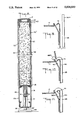
- FIG. 18 is a sectional view of the base for supporting a panel
- FIG. 19 is a plan view of the base
- FIG. 20 is a longitudinal section taken through the base and the panel supported thereby.
- FIG. 21 is a perspective view illustrating how a connector post is joined to a panel by way of a standard.
- FIG. 1 there is shown a space divider system in accordance with the invention adapted to create a desired spatial pattern in an interior.
- the system is composed of free standing modular panels 10A to 10G that are interlocked to create a work station in which panels 10B and 10C are joined together in side-by-side relation to form a short partition wall at right angles to a longer partition wall formed by panels 10D, 10E and 10F, also joined together in side-by-side relation.
- Panel 10A is at right angles to the free end of the short wall, while panel 10G is at right angles to the longer wall to create an alcove.
- Cantilevered from panel 10B is an overhead cabinet 11, and cantilevered from panels 10D and 10E is a shelf 12.
- Table surfaces 13, 14, and 15 are cantilevered from the panels, surface 13 resting on a set of drawers and surface 15 on a base 16.
- FIG. 1 The spatial pattern shown in FIG. 1 is merely by way of illustrating one of many possible space divisions. As will later be evident, the panels may be joined serially in side-by-side relation as well as in right angle relation to sub-divide a space in any desired manner. But regardless of the pattern, it has a right angle geometry to create three-dimensional working stations.
- Each panel as shown separately in FIGS. 2 and 3, includes a rectangular frame composed of mitered top and bottom and side channel pieces 17, 18, 19 and 20 which are held together at their corners by four identical clips 21. Bonded to the opposing faces of the frame are sheets 22' and 22" which may be of expanded metal or other light weight material. The panel rests on a base 23 which is shown in greater detail in FIG. 4.
- base 23 is constituted by a channel element 24 whose floor is provided with holes 24a and 24b through which are inserted the stems 25' and 26' of ground pedestals 25 and 26. These stems extend through tubes formed in spacer elements 27 and 28 on which the lower piece 18 of the panel frame is mounted at a position raised above element 24. Suspended from the lower piece of the panel and contained within channel element 24 between spacer elements 27 and 28 is a narrow duct 29.
- the duct is formed by parallel vertical walls having upper flanges 29a and 29b which are secured to the lower piece 18 of the panel frame.
- a raceway is created by side plates 30 and 31 which, as shown in FIG. 8, snap onto the opposite sides of channel element 24 and the lower piece 18 of the frame and are provided with windows 30a and 30b having removable covers 32 and 33 to permit the installation in the windows of electrical outlets.
- wires W which run through duct 29. These wires may be telephone and other low-voltage communication lines.
- an electrical outlet E is installed in side plate 31 of the raceway 23 connected to power lines running through the raceway.
- the window in side plate 30 remains covered by cover plate 32.
- each clip is formed by a strip of metal whose ends are folded over to define jaws 21A and 21B at right angles to each other, the jaws being interconnected by the midportion 21C of the strip which is at a 45-degree angle thereto.
- the corners then each have a side entry or recess 35 and horizontal and vertical side ledges which border this recess, these side ledges being formed by the clip jaws in engagement with the struts.
- the side ledges are provided with threaded bores 36 to receive holding screws.
- a pad 37 of light-weight sound-absorbent material is installed within the panel frame between metal sheets 22' and 22", as shown in FIGS. 8 and 20, in order to impart sound-absorbing properties to the panels, installed within the panel frame between metal sheets 22' and 22", as shown in FIGS. 8 and 20, in order to impart sound-absorbing properties to the panels, installed within the panel frame between metal sheets 22' and 22", as shown in FIGS. 8 and 20, is a pad 37 of light-weight sound-absorbent material. To finish the panel and impart an attractive appearance thereto, the panel is covered on either face by fabric sheets 38 and 39 whose margins are stuffed into a storage channel 42 which runs along the periphery of the frame. This storage channel is formed by a resilient metal leaf 40 whose free end is bent into a crook 41 that is spaced from the frame to create the restricted entry to the channel.
- FIGS. 9, 10 and 11 The manner by which a fabric sheet is attached to the frame is illustrated in FIGS. 9, 10 and 11.
- fabric sheet 38 is first brought to a position parallel to the frame in which its margins 38M extends above storage channel 42. Then by means of the blade 43 of a hand tool, as shown in FIG. 10, margin 38 is forced into the restrict ed entry of storage channel 42, the resilient leaf 40 yielding to permit such entry. The margin is thereby caused to fold over crook 41 to rest within the storage channel and thereby retain the fabric sheet against the frame.
- the rectangular dimensions of the fabric sheet must somewhat exceed those of the frame to allow for margins to be stuffed into the peripheral storage channel.
- the fabric sheets which represent the external faces of the panel are exposed to the public, they are subject to wear and tear as well as soiling. But because these fabric sheets, though firmly secured to the frame are readily removable therefrom by the same tool which can then be used to pry open the entry to the storage channel, a damaged or soiled fabric can be replaced without difficulty. Or if a decor change is made in the interior space requiring a different color or wall texture scheme, the panels may then be provided with fabrics appropriate to this scheme.
- mouldings M are provided, as shown in FIG. 8, which snap onto the frame pieces.
- the frame shown is composed of separate pieces which are united by corner clips which create side ledges
- the frame may be made of pieces that are welded together and which include horizontal and vertical side ledges; for these ledges, as will later be evident, are essential for interlocking the panels into a desired spatial pattern.
- the modular panels must be interlocked in side-by-side relation to form planar partition walls, and they must also be interlocked in right angle relation to create walls normal to the partition wall.
- the elements necessary in a system in accordance with the invention to provide side-by-side and right-angle panel junctions are a standard 44 and a connector post 45. These elements are mechanically coupled to the panels by means of clamps 46 which are secured to the ends of the standards by screws 47.
- FIG. 5 The basic interlocking arrangement is illustrated in FIG. 5, where it will be seen that modular panels 10A and 10B are joined together in side-by-side relation by a standard 44 which is sandwiched between the adjacent vertical sides of the panel frames, the panels being interlocked by clamps 46 secured to the ends of the standard by screws 47.
- Panel 10C is joined to panel 10B at right angles thereto by connector post 45.
- panel 10B is locked to one side of this post by means of a standard 44 interposed between the panel side and the corresponding side of the post, and another standard 44 interposed between a side of the post at right angles to the one side and the corresponding side of panel 10C.
- Clamps 46 and screws 47 which are secured to the two standards, serve to lock panels 10B and 10C to connector post 45 at right angles to each other.
- each standard 44 which has a rectangular cross section is provided at either face thereof with a longitudinal row of rectangular slots 48 adapted to receive hooks for cantilevering a component from the standard.
- Each end of the standard has side notches to provide an end opening to accommodate the flat base 46A of clamp 46, from which base extend a pair of downwardly sloped wings 46B and 46C.
- Clamp base 46A has a center bore that registers with a threaded socket 49 when the base is seated thereon. (It is to be noted that the stems 26' of the pedestals of levelling devices 26 may be screwed into the bottom threaded socket 49 of a standard rather than onto the base of the panel frame.)
- a stiffener plate 50 is provided which straddles the end of the standard and is secured to the horizontal ledges 21A of the frames on either side of the standard by screws 51 which are received in the threaded bores 36.
- Each connector post 45 is of hollow four-side construction, the inner surface of the sides having parallel reinforcing ribs 45R formed therein.
- the four sides of the ends of the post have rectangular notches cut therein to define side ledges 45L.
- the four-sided connector post makes it possible, should the spatial pattern to be erected so require, to connect panels 10A, 10B, 10C and 10D in a cruciform arrangement in which panel 10B and 10D are at right angles to panels 10A and 10C which lie in the same plane.
- the upper end of standard 53 is joined to the upper right corner of the frame of panel 10A by a clamp 46 which is secured to the standard.
- the lower end of the two panels are locked together by a clamp 46 which bridges the horizontal struts on these panels.
- the various work components such as shelf 12 shown in FIG. 1, which are mounted on the panels are provided, as shown in FIG. 7, with brackets 55 whose rear edge has a row of hooks 56. These are received in the notches 48 in the standard interposed between the panels, thereby cantilevering the work component from the standard.
- the notches are of double width and can therefore accept a pair of brackets, so that two work components may be cantilevered in side-by-side relation without any space therebetween.
- each work component Since there is a standard at the junction of every two panels, one has merely to design each work component so that the rear brackets are in line with the standards.
- a work component must have at least two spaced-apart brackets so that it can be stably supported from a partition wall; and in some cases where the work component is long, it may have three or four brackets.
- the system is highly flexible; for one may interlock the panels to create a large range of different spatial patterns having a right angle geometry to exploit an available interior space to best advantage.
- bent metal clips 21 for joining the mitered pieces of the frame together are not the invention of the applicant herein, these clips being the invention of Robert E. Reuter.
Abstract
Description
Claims (1)
Priority Applications (1)
| Application Number | Priority Date | Filing Date | Title |
|---|---|---|---|
| US06/803,552 US5024030A (en) | 1983-12-13 | 1985-12-02 | Space divider system |
Applications Claiming Priority (2)
| Application Number | Priority Date | Filing Date | Title |
|---|---|---|---|
| US06/560,877 US4567698A (en) | 1983-12-13 | 1983-12-13 | Space divider system |
| US06/803,552 US5024030A (en) | 1983-12-13 | 1985-12-02 | Space divider system |
Related Parent Applications (1)
| Application Number | Title | Priority Date | Filing Date |
|---|---|---|---|
| US06/560,877 Division US4567698A (en) | 1983-12-13 | 1983-12-13 | Space divider system |
Publications (1)
| Publication Number | Publication Date |
|---|---|
| US5024030A true US5024030A (en) | 1991-06-18 |
Family
ID=27072490
Family Applications (1)
| Application Number | Title | Priority Date | Filing Date |
|---|---|---|---|
| US06/803,552 Expired - Lifetime US5024030A (en) | 1983-12-13 | 1985-12-02 | Space divider system |
Country Status (1)
| Country | Link |
|---|---|
| US (1) | US5024030A (en) |
Cited By (35)
| Publication number | Priority date | Publication date | Assignee | Title |
|---|---|---|---|---|
| GB2277256A (en) * | 1993-04-05 | 1994-10-26 | Byrum As | Building system for modular furniture |
| WO1996008617A1 (en) * | 1994-09-16 | 1996-03-21 | Panel Concepts, Inc. | Wall partition connector |
| US5685113A (en) * | 1995-06-05 | 1997-11-11 | Knoll, Inc. | Lay-in wireways for a space divider system |
| US5724779A (en) * | 1996-10-18 | 1998-03-10 | Chang; Ching-Chang | Partition wall unit |
| US5852904A (en) * | 1996-08-05 | 1998-12-29 | Haworth, Inc. | Panel arrangement |
| US5921040A (en) * | 1997-06-03 | 1999-07-13 | Knoll, Inc. | Panel frame assembly |
| USD416721S (en) * | 1998-05-28 | 1999-11-23 | Herman Miller, Inc. | Shelf unit |
| USD417572S (en) * | 1998-05-28 | 1999-12-14 | Herman Miller, Inc. | Shelf unit |
| US6000179A (en) * | 1996-12-13 | 1999-12-14 | Steelcase Inc. | Stacking panel and off-module panel connections |
| US6021613A (en) * | 1997-05-28 | 2000-02-08 | Knoll, Inc. | Hybrid office panel construction for a modular office furniture system |
| US6112485A (en) * | 1998-11-04 | 2000-09-05 | Haworth, Inc. | Post-panel connector arrangement |
| US6112472A (en) * | 1998-09-14 | 2000-09-05 | Steelcase Development Inc. | Integrated furniture system including overhead framework system and partition system |
| US6314687B1 (en) * | 1996-06-07 | 2001-11-13 | Gerald Schondelmayer | Wall panel covering |
| US6389773B1 (en) | 1999-06-04 | 2002-05-21 | Knoll, Inc. | Stackable panel system for modular office furniture |
| US6481163B1 (en) * | 2000-10-20 | 2002-11-19 | Steelcase Development Corporation | Partition panel |
| US6711871B2 (en) | 2000-05-03 | 2004-03-30 | Herman Miller, Inc. | Wall panel with off-module components |
| US6889477B1 (en) * | 2000-10-06 | 2005-05-10 | Hni Technologies Inc. | Modular wall panel construction |
| US20060032186A1 (en) * | 2004-07-30 | 2006-02-16 | Enzo Vardaro | Adjustable wall system |
| US20060137260A1 (en) * | 2004-09-02 | 2006-06-29 | Jo Shernaman | Modular wall, inventory display and product and service marketing systems |
| US20140311036A1 (en) * | 2013-03-15 | 2014-10-23 | Herman Miller, Inc. | Screen assembly |
| US9032682B2 (en) | 2012-12-10 | 2015-05-19 | Target Brands, Inc. | Free-standing wall |
| EP2904167A4 (en) * | 2012-10-05 | 2016-10-12 | Dirtt Environmental Solutions | Center-mounted acoustical substrates |
| US9546483B2 (en) | 2012-10-05 | 2017-01-17 | Dirtt Environmental Solutions, Ltd. | Modular walls with seismic-shiftability |
| US9649831B2 (en) | 2012-10-05 | 2017-05-16 | Dirtt Environmental Solutions, Ltd | Perforated acoustic tiles |
| US20180350277A1 (en) * | 2017-06-02 | 2018-12-06 | Michael Entwistle | Media wall |
| USD927728S1 (en) * | 2018-02-23 | 2021-08-10 | Safe Skies, Llc | Trade show booth display |
| USD945013S1 (en) * | 2018-12-28 | 2022-03-01 | Safe Skies, Llc | Trade show booth display |
| USD946324S1 (en) * | 2018-07-31 | 2022-03-22 | Apple Inc. | Retail fixture group |
| US11297940B2 (en) * | 2016-10-18 | 2022-04-12 | Dataflex International B.V. | Office workplace system |
| USD959860S1 (en) * | 2020-05-08 | 2022-08-09 | Mendel Jaroslawitz | Room divider |
| US11606868B2 (en) | 2020-08-03 | 2023-03-14 | Urben Technologies Limited | Display unit |
| USD991712S1 (en) * | 2020-06-23 | 2023-07-11 | Polestar Performance Ab | Retail display |
| USD991714S1 (en) | 2020-06-23 | 2023-07-11 | Polestar Performance Ab | Retail display |
| USD1005750S1 (en) * | 2020-06-23 | 2023-11-28 | Polestar Performance Ab | Room with retail arrangement |
| USD1021138S1 (en) * | 2021-12-23 | 2024-04-02 | Flos S.P.A. | Shop interior arrangement |
Citations (6)
| Publication number | Priority date | Publication date | Assignee | Title |
|---|---|---|---|---|
| US3164260A (en) * | 1962-07-17 | 1965-01-05 | Seeman Werner | Display rack construction |
| US3425171A (en) * | 1966-02-09 | 1969-02-04 | Miller Herman Inc | Space divider system |
| US3517467A (en) * | 1968-06-17 | 1970-06-30 | Miller Herman Inc | Structural support system for shelving |
| US4093078A (en) * | 1976-06-30 | 1978-06-06 | Ready Metal Manufacturing Company | Tandem merchandise display equipment |
| US4325597A (en) * | 1980-03-27 | 1982-04-20 | Knoll International, Inc. | Furniture systems |
| US4567698A (en) * | 1983-12-13 | 1986-02-04 | Knoll International, Inc. | Space divider system |
-
1985
- 1985-12-02 US US06/803,552 patent/US5024030A/en not_active Expired - Lifetime
Patent Citations (6)
| Publication number | Priority date | Publication date | Assignee | Title |
|---|---|---|---|---|
| US3164260A (en) * | 1962-07-17 | 1965-01-05 | Seeman Werner | Display rack construction |
| US3425171A (en) * | 1966-02-09 | 1969-02-04 | Miller Herman Inc | Space divider system |
| US3517467A (en) * | 1968-06-17 | 1970-06-30 | Miller Herman Inc | Structural support system for shelving |
| US4093078A (en) * | 1976-06-30 | 1978-06-06 | Ready Metal Manufacturing Company | Tandem merchandise display equipment |
| US4325597A (en) * | 1980-03-27 | 1982-04-20 | Knoll International, Inc. | Furniture systems |
| US4567698A (en) * | 1983-12-13 | 1986-02-04 | Knoll International, Inc. | Space divider system |
Cited By (47)
| Publication number | Priority date | Publication date | Assignee | Title |
|---|---|---|---|---|
| GB2277256B (en) * | 1993-04-05 | 1997-01-08 | Byrum As | Building system for moveables |
| GB2277256A (en) * | 1993-04-05 | 1994-10-26 | Byrum As | Building system for modular furniture |
| WO1996008617A1 (en) * | 1994-09-16 | 1996-03-21 | Panel Concepts, Inc. | Wall partition connector |
| US5694729A (en) * | 1994-09-16 | 1997-12-09 | Panel Concepts, Inc. | Wall partition connector |
| US5685113A (en) * | 1995-06-05 | 1997-11-11 | Knoll, Inc. | Lay-in wireways for a space divider system |
| US5918433A (en) * | 1995-06-05 | 1999-07-06 | Knoll, Inc. | Lay-in wireways for a space divider system |
| US6314687B1 (en) * | 1996-06-07 | 2001-11-13 | Gerald Schondelmayer | Wall panel covering |
| US6161347A (en) * | 1996-08-05 | 2000-12-19 | Haworth, Inc. | Panel arrangement |
| US5852904A (en) * | 1996-08-05 | 1998-12-29 | Haworth, Inc. | Panel arrangement |
| US5724779A (en) * | 1996-10-18 | 1998-03-10 | Chang; Ching-Chang | Partition wall unit |
| US6000179A (en) * | 1996-12-13 | 1999-12-14 | Steelcase Inc. | Stacking panel and off-module panel connections |
| US6021613A (en) * | 1997-05-28 | 2000-02-08 | Knoll, Inc. | Hybrid office panel construction for a modular office furniture system |
| US6167664B1 (en) | 1997-05-28 | 2001-01-02 | Knoll, Inc. | Hybrid office panel construction for a modular office furniture system |
| US6367213B1 (en) | 1997-05-28 | 2002-04-09 | Knoll, Inc. | Hybrid office panel construction for a modular office furniture system |
| US7310918B1 (en) | 1997-05-28 | 2007-12-25 | Knoll, Inc. | Hybrid office panel construction for a modular office furniture system |
| US5921040A (en) * | 1997-06-03 | 1999-07-13 | Knoll, Inc. | Panel frame assembly |
| USD417572S (en) * | 1998-05-28 | 1999-12-14 | Herman Miller, Inc. | Shelf unit |
| USD416721S (en) * | 1998-05-28 | 1999-11-23 | Herman Miller, Inc. | Shelf unit |
| US6112472A (en) * | 1998-09-14 | 2000-09-05 | Steelcase Development Inc. | Integrated furniture system including overhead framework system and partition system |
| US6112485A (en) * | 1998-11-04 | 2000-09-05 | Haworth, Inc. | Post-panel connector arrangement |
| US6389773B1 (en) | 1999-06-04 | 2002-05-21 | Knoll, Inc. | Stackable panel system for modular office furniture |
| US6711871B2 (en) | 2000-05-03 | 2004-03-30 | Herman Miller, Inc. | Wall panel with off-module components |
| US6889477B1 (en) * | 2000-10-06 | 2005-05-10 | Hni Technologies Inc. | Modular wall panel construction |
| US6481163B1 (en) * | 2000-10-20 | 2002-11-19 | Steelcase Development Corporation | Partition panel |
| US20060032186A1 (en) * | 2004-07-30 | 2006-02-16 | Enzo Vardaro | Adjustable wall system |
| US7712260B2 (en) | 2004-07-30 | 2010-05-11 | Groupe Artitalia Inc. | Adjustable wall system |
| US20100218432A1 (en) * | 2004-07-30 | 2010-09-02 | Enzo Vardaro | Adjustable wall system |
| US20060137260A1 (en) * | 2004-09-02 | 2006-06-29 | Jo Shernaman | Modular wall, inventory display and product and service marketing systems |
| EP2904167A4 (en) * | 2012-10-05 | 2016-10-12 | Dirtt Environmental Solutions | Center-mounted acoustical substrates |
| US9546483B2 (en) | 2012-10-05 | 2017-01-17 | Dirtt Environmental Solutions, Ltd. | Modular walls with seismic-shiftability |
| US9649831B2 (en) | 2012-10-05 | 2017-05-16 | Dirtt Environmental Solutions, Ltd | Perforated acoustic tiles |
| US9032682B2 (en) | 2012-12-10 | 2015-05-19 | Target Brands, Inc. | Free-standing wall |
| US20140311036A1 (en) * | 2013-03-15 | 2014-10-23 | Herman Miller, Inc. | Screen assembly |
| US9255440B2 (en) * | 2013-03-15 | 2016-02-09 | Herman Miller, Inc. | Screen assembly |
| US11297940B2 (en) * | 2016-10-18 | 2022-04-12 | Dataflex International B.V. | Office workplace system |
| US10636334B2 (en) * | 2017-06-02 | 2020-04-28 | Ccomm Group Ltd. | Media wall |
| US20180350277A1 (en) * | 2017-06-02 | 2018-12-06 | Michael Entwistle | Media wall |
| USD927728S1 (en) * | 2018-02-23 | 2021-08-10 | Safe Skies, Llc | Trade show booth display |
| USD946324S1 (en) * | 2018-07-31 | 2022-03-22 | Apple Inc. | Retail fixture group |
| USD1015030S1 (en) * | 2018-07-31 | 2024-02-20 | Apple Inc. | Retail fixture group |
| USD945013S1 (en) * | 2018-12-28 | 2022-03-01 | Safe Skies, Llc | Trade show booth display |
| USD959860S1 (en) * | 2020-05-08 | 2022-08-09 | Mendel Jaroslawitz | Room divider |
| USD991712S1 (en) * | 2020-06-23 | 2023-07-11 | Polestar Performance Ab | Retail display |
| USD991714S1 (en) | 2020-06-23 | 2023-07-11 | Polestar Performance Ab | Retail display |
| USD1005750S1 (en) * | 2020-06-23 | 2023-11-28 | Polestar Performance Ab | Room with retail arrangement |
| US11606868B2 (en) | 2020-08-03 | 2023-03-14 | Urben Technologies Limited | Display unit |
| USD1021138S1 (en) * | 2021-12-23 | 2024-04-02 | Flos S.P.A. | Shop interior arrangement |
Similar Documents
| Publication | Publication Date | Title |
|---|---|---|
| US4567698A (en) | Space divider system | |
| US5024030A (en) | Space divider system | |
| US5642593A (en) | Knockdown and reassemble office partition | |
| US3788378A (en) | Floor area divider | |
| US4876835A (en) | Work space management system | |
| US7540115B2 (en) | Partition system | |
| US3768222A (en) | Partition device | |
| EP0247052B1 (en) | Partition panel system | |
| US6220186B1 (en) | Modular interior furnishing system | |
| US5024167A (en) | Desk system | |
| US8393122B2 (en) | Partition system | |
| US3892189A (en) | Modular shelf construction | |
| US6389773B1 (en) | Stackable panel system for modular office furniture | |
| US4601137A (en) | Locking mechanism for an office panel system | |
| US3871153A (en) | Partition device | |
| US4817538A (en) | Construction system for shelves | |
| US4905334A (en) | Refurbishing panel system for space divider partition walls | |
| US7100999B2 (en) | System of interlocking storage and display modules connectable in a plurality of different configurations | |
| US3525560A (en) | Frame structure | |
| US3418765A (en) | Coordinated system for activity isolation | |
| US4031675A (en) | Free standing redecoratable vertical wall or divider | |
| US5950371A (en) | Column mountable shelf for furniture systems | |
| CA1325508C (en) | Panel connection arrangement for a partition system | |
| GB2175029A (en) | Office partition comprising cable conduit | |
| IT9067365A1 (en) | PROCEDURE FOR THE PRODUCTION OF OFFICE FURNITURE SYSTEMS AND OFFICE FURNITURE GROUP |
Legal Events
| Date | Code | Title | Description |
|---|---|---|---|
| AS | Assignment |
Owner name: KNOLL INTERNATIONAL, INC., 655 MADISON AVENUE, NEW Free format text: ASSIGNMENT OF ASSIGNORS INTEREST.;ASSIGNOR:MORRISON, ANDREW I.;REEL/FRAME:004490/0279 Effective date: 19851129 |
|
| STCF | Information on status: patent grant |
Free format text: PATENTED CASE |
|
| FEPP | Fee payment procedure |
Free format text: PAYOR NUMBER ASSIGNED (ORIGINAL EVENT CODE: ASPN); ENTITY STATUS OF PATENT OWNER: LARGE ENTITY |
|
| FPAY | Fee payment |
Year of fee payment: 4 |
|
| AS | Assignment |
Owner name: WESTINGHOUSE ELECTRIC CORPORATION, PENNSYLVANIA Free format text: ASSIGNMENT OF ASSIGNORS INTEREST;ASSIGNOR:KNOLL INTERNATIONAL, INC.;REEL/FRAME:007453/0524 Effective date: 19950417 |
|
| AS | Assignment |
Owner name: NATIONSBANK, N.A., AS COLLATERAL AGENT, NORTH CARO Free format text: SECURITY AGREEMENT;ASSIGNOR:KNOLL, INC.;REEL/FRAME:007803/0214 Effective date: 19960228 |
|
| AS | Assignment |
Owner name: KNOLL, INC., PENNSYLVANIA Free format text: ASSIGNMENT OF ASSIGNORS INTEREST;ASSIGNOR:WESTINGHOUSE ELECTRIC CORPORATION;REEL/FRAME:007888/0022 Effective date: 19960229 |
|
| AS | Assignment |
Owner name: KNOLL, INC., PENNSYLVANIA Free format text: RELEASE BY SECURED PARTY;ASSIGNOR:NATIONSBANK, N.A. AS COLLATERAL AGENT;REEL/FRAME:008660/0504 Effective date: 19970806 |
|
| FPAY | Fee payment |
Year of fee payment: 8 |
|
| REMI | Maintenance fee reminder mailed | ||
| AS | Assignment |
Owner name: BANK OF AMERICA, N.A., AS COLLATERAL AGENT, NORTH Free format text: NOTICE OF GRANT OF SECURITY INTEREST;ASSIGNOR:KNOLL, INC.;REEL/FRAME:010360/0001 Effective date: 19991020 |
|
| FPAY | Fee payment |
Year of fee payment: 12 |
|
| AS | Assignment |
Owner name: KNOLL, INC., PENNSYLVANIA Free format text: RELEASE OF SECURITY INTEREST IN PATENT COLLATERAL (RF 010360/0001);ASSIGNOR:BANK OF AMERICA, N.A.;REEL/FRAME:015215/0024 Effective date: 20040928 Owner name: UBS AG, STAMFORD BRANCH, CONNECTICUT Free format text: SECURITY AGREEMENT;ASSIGNOR:KNOLL, INC.;REEL/FRAME:015215/0366 Effective date: 20040929 |
|
| AS | Assignment |
Owner name: BANK OF AMERICA, N.A., ILLINOIS Free format text: ASSIGNMENT OF SECURITY AGREEMENT;ASSIGNOR:UBS AG, STAMFORD BRANCH;REEL/FRAME:016735/0753 Effective date: 20051003 |
|
| AS | Assignment |
Owner name: KNOLL, INC., PENNSYLVANIA Free format text: TERMINATION OF SECURITY INTEREST;ASSIGNOR:BANK OF AMERICA, N.A., SUCCESSOR IN INTEREST TO UBS AG STAMFORD BRANCH;REEL/FRAME:019562/0191 Effective date: 20070629 |
|
| AS | Assignment |
Owner name: BANK OF AMERICA, N.A., AS ADMINISTRATIVE AGENT, IL Free format text: NOTICE OF GRANT OF SECURITY INTEREST;ASSIGNOR:KNOLL, INC.;REEL/FRAME:019580/0808 Effective date: 20070629 |
|
| AS | Assignment |
Owner name: KNOLL, INC., PENNSYLVANIA Free format text: TERMINATION AND RELEASE OF SECURITY INTEREST IN PATENTS;ASSIGNOR:BANK OF AMERICA, N.A., AS ADMINISTRATIVE AGENT;REEL/FRAME:056990/0902 Effective date: 20210719 Owner name: KNOLL, INC., PENNSYLVANIA Free format text: TERMINATION AND RELEASE OF SECURITY INTEREST IN PATENTS;ASSIGNOR:BANK OF AMERICA, N.A. (AS SUCCESSOR-BY-ASSIGNMENT TO UBS AG, STAMFORD BRANCH), AS ADMINISTRATIVE AGENT;REEL/FRAME:056990/0917 Effective date: 20210719 |