US5020244A - Method and apparatus for drying liquid on printed media - Google Patents
Method and apparatus for drying liquid on printed media Download PDFInfo
- Publication number
- US5020244A US5020244A US07/444,262 US44426289A US5020244A US 5020244 A US5020244 A US 5020244A US 44426289 A US44426289 A US 44426289A US 5020244 A US5020244 A US 5020244A
- Authority
- US
- United States
- Prior art keywords
- media
- housing
- air
- opening
- media path
- Prior art date
- Legal status (The legal status is an assumption and is not a legal conclusion. Google has not performed a legal analysis and makes no representation as to the accuracy of the status listed.)
- Expired - Lifetime
Links
Images


Classifications
-
- B—PERFORMING OPERATIONS; TRANSPORTING
- B41—PRINTING; LINING MACHINES; TYPEWRITERS; STAMPS
- B41J—TYPEWRITERS; SELECTIVE PRINTING MECHANISMS, i.e. MECHANISMS PRINTING OTHERWISE THAN FROM A FORME; CORRECTION OF TYPOGRAPHICAL ERRORS
- B41J11/00—Devices or arrangements of selective printing mechanisms, e.g. ink-jet printers or thermal printers, for supporting or handling copy material in sheet or web form
- B41J11/0015—Devices or arrangements of selective printing mechanisms, e.g. ink-jet printers or thermal printers, for supporting or handling copy material in sheet or web form for treating before, during or after printing or for uniform coating or laminating the copy material before or after printing
- B41J11/002—Curing or drying the ink on the copy materials, e.g. by heating or irradiating
- B41J11/0022—Curing or drying the ink on the copy materials, e.g. by heating or irradiating using convection means, e.g. by using a fan for blowing or sucking air
Definitions
- This invention teaches an enhanced drying apparatus and method in which the three factors, air velocity relative to a medium surface, temperature of the blown air, and the relative humidity of the blown air, are optimized.
- This is accomplished by use of a fan constructed of a cylinder rotatably mounted within a housing with impeller blades mounted around the outer circumference of the cylinder.
- a housing encloses the fan to create an air chamber and air is drawn into the chamber from a thin cavity created over a media path by a shroud.
- This air has previously been heated by a heating element arranged either along the media path or within the housing.
- Air dams are created at the entrance and the exit points of the cavity formed by the media path and a baffle mounted within the housing and an extended shroud attached to the housing. This baffle directs the heated air onto the media at high velocity.
- the reheated air has a lower relative humidity than newly heated ambient air and reheating lowers the amount of energy needed to heat the blown air.
- FIG. 1 shows a blower and heater combination acting on a media path.
- FIG. 2 shows a blower with an extended shroud with a heater element therein acting on a media path.
- FIG. 3 shows a blower with an extended shroud extended to the left, along a media path, with a heater element within the shroud, for acting on media on the media path, moving from left to right.
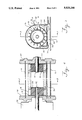
- FIG. 4 shows a half section view of a typical blower and heater unit.
- FIG. 5 shows a cross section of a typical blower along the cross section lines A--A.
- FIG. 6 shows an alternate configuration for the blower heater combination along an inclined media path.
- a media 2 has ink deposited on it by print head 4, reacting against a platen 6.
- a drive roller 8 acts on the media 2 by rotational force to advance the media which has pressure applied to it by star wheel 10 to maintain frictional contact with the drive roller 8.
- a guide 12 receives the media 2, as it is advanced away from the printing action where wet ink has been applied. At this stage the ink has not yet set. It is within the scope of this invention that other liquids may be deposited on a media 2, to be acted upon, by the drying process which is now being disclosed.
- FIG. 1 there is shown a housing 14, that is partially open toward and adjacent to the guide 12, on which the media 2 is advanced.
- the housing may be of may different shapes, but in the embodiment shown, it is a thin tunnel shape with its length perpendicular to the path of the media 2.
- Mounted within the housing 14, is a fan 16.
- the positioning of the fan 16 and the housing 14 creates a chamber 17.
- the fan 16 is rotatably mounted within the housing 14, in axial alignment with the axis of the tunnel shaped housing 14.
- the fan 16 is a cross-flow fan with impellers 18 mounted on the outer cylindrical circumference 20 of the fan 16.
- Mounted within the housing 14, between the fan 16 and the guide 12 is a baffle 22.
- the baffle 22 serves two purposes.
- Air holes 28 in the housing 14 allow ambient air to enter the chamber 17 at a regulated rate.
- a heating element 30, as shown in FIG. 1, is affixed to the baffle 22, between it and the guide 12. As air is forced through the second opening 26, it is directed by the housing wall 32 to a thin gap 33 between the baffle 22 and the guide 12. Preferably, this air is supplied at high velocity which aids in the drying of ink on the media 2. In the path of this air stream is the heating element 30, which heats the air blown onto the media 2.
- the first opening 24, created by the baffle 22 and the housing 14, partially draws this air stream back into the chamber 17, by the action of fan 16.
- a shroud 34 extends from housing 14, generally parallel to the guide 12 and away from the housing 14 in the direction of media flow from left to right.
- Another function of the high velocity air blown into the cavity 33 is to hold the media 2 against the guide 12 which keeps the wet ink from being smudged by contact with baffle 22 and shroud 34.
- the recirculation of heated air shown in FIG. 1, as well as the succeeding figures, is beneficial because the reheated air requires less energy to heat and has a reduced relative humidity as compared to ambient air.
- the recirculation of heated air increases the equilibrium temperature of the air within cavity 33 in which the media travels, and also slightly raises the specific humidity of the air in the cavity 33, due to the evaporated ink. Except for sustained heavy printing, this does not have enough effect on relative humidity to significantly affect drying time.
- ⁇ t 1 temperature increase for one pass with no recirculation
- t total flow rate of air exiting fan, before recirculation; includes recirculation
- FIG. 2 Shown in FIG. 2 is an alternate embodiment with a rightwardly extended baffle 38 extended from the housing 14 from left to right, between the shroud 34 and the guide 12, to form a recirculation opening 40.
- a heating element 30 is affixed to baffle 38 between it and shroud 34 to heat air blown across the surface of media 2 as it moves left to right along guide 12.
- a shroud lip 42 is tapered to reduce the exit path of media 2, which in cooperation with the air drawn back into recirculation at recirculation opening 40, before the media 2 exits the shroud 34, creates an air dam to restrict the escape of heated air. Variations in the shape of shroud lip 42 will vary the exit opening for the media 2 which in turn will regulate the volume of escaping air and in turn the volume of recirculated heated air.
- FIG. 3 shows an another embodiment where the shroud 34 extends from right to left from a housing 14.
- a shroud lip 44 acts to reverse the direction of air flow and bring it back over the printed media for partial recirculation at air dam 42.
- the media 2 helps form a portion of the drying cavity 35.
- a heating element 30 is mounted within the shroud 34 and heated air is drawn into the housing 14 to the right of the leftwardly extended baffle 45 where between it and an edge of the housing 14 there is formed an exit opening 46 for the advancing media 2. Just prior to this exit opening, air is drawn into chamber 17 through recirculation opening 48 for recirculation.
- FIG. 4 shows a frontal cross section of the fan 16 in housing 14.
- a motor 50 drives a shaft 52 on which is rotatably mounted in a silicon rubber toroid 54.
- the silicon rubber toroid 54 is mounted in fan 16 which is made of aluminum or plastic. Other suitable materials may be used as well for the construction of the fan and toroid.
- the drive shaft 52 is secured to the fan 16 which is mounted between the housing walls 58 and 60.
- the fan 16 is rotatably attached to a Nylatron toroid 55 which is supported by a bearing shaft 62 stationarily mounted on the housing wall 60 opposite to the housing wall 58 through which the drive shaft 52 is mounted.
- FIG. 5 shows a cross section of the fan 16 in housing 14 along the section line A-A in FIG. 4.
- the fan 16 is a cylinder with impellers 18 radiating outwardly.
- the cylinder of fan 16 along with the inner wall of housing 14 create a chamber 17, into which air is drawn by the rotation of fan 16 at the first opening 24 created by the baffle 22 and the housing 14 wall and exhausted at the second opening 26, into the cavity 33 between the baffle 22 and the guide 12, to dry media that is advanced through this cavity.
- Some ambient air will be drawn into the chamber 17 through the inlet 70 into which media 2 is advanced.
- the action of drawing in ambient air, at inlet 70, into the recirculation stream of fan 16, in cavity 33 acts to block heated air from escaping, thereby forming an air dam at inlet 70.
- FIG. 5 Also shown in FIG. 5 are alternate configurations for arranging the heating elements.
- a heating element 30 is shown mounted on the baffle between it and the guide 12 in the path of media 2.
- An alternate configuration is shown in which a heating coil 64 is mounted inside the baffle structure.
- a heating element may be mounted at multiple positions within housing 14.
- FIGS. 4 and 5 Another feature shown in FIGS. 4 and 5 is the detail for mounting the baffle 22, the housing 14, and the guide 12 onto the housing walls 58 and 60.
- the baffle 22, the guide 12, and housing 14, are held between housing walls 58 and 60, by recesses therein.
- baffle 22 is affixed to the housing 14 by a flange 66 which has ports in it for receiving air drawn into the chamber 17 by the fan 16.
- Flange 66 acts both as a support and as a means of regulating air flow into the chamber 17.
- the recirculation of heated air has been shown to be accomplished by drawing heated air into the chamber 17 for exhausting onto a media 2 in a cavity 33 where the air is again partially drawn back into the chamber 17 for reheating.
- the amount of air that is reheated and the amount of new air drawn into the chamber for recirculation is a function of the size of the inlet 70 and the amount of air that seeps in through seams in the housing 14.
- the air drawn into the chamber 17 at the first opening 24 has little ambient air content as a result of the exhausted air stream creating an air dam, which is here directed in the path of the media 2 as indicated by the arrows indicating air flow in FIG. 5. Additional ambient air input may be achieved by an ambient air inlet 68 in the housing 14. Depending on the amount of reheating required, larger or smaller openings may be used to create the desired mix of ambient and reheated air in chamber 17.
- FIG. 6 shows an alternate embodiment with the apparatus tilted along a slanted path.
- Heating element 30, is mounted on an elongated baffle 72, within extended shroud 74, which in turn is attached to housing 14.
- Media 2 is drawn in along a paper path and enters the cavity 75 formed by elongated baffle 72 and guide 12 at opening 76.
- the heated air from the action of heating element 30, is directed onto the media 2 at opening 76 and from thence on down the media's 2 path in cavity 75 where a portion of it is drawn into chamber 17 as has been previously described for recirculation.
- a portion of the heated air continues down the path of the media 2 in cavity 75 and exits at point 78, which is an outlet formed by a second baffle 80 which in turn, runs generally parallel to guide 12 to form a thin exhaust cavity 77 through which the media 2 passes with heated high velocity air being passed over its surface.
- This configuration has the advantage of having an extended drying cavity, as can be seen from examination of the drawing. It also demonstrates that the invention may be employed in different elevations other than horizontal.
- the drying air is supplied at high velocity.
- One successful fan 16 configuration which was used to achieve this result uses a long, small diameter fan 16, which extends across the media 2 width.
- the impeller's 18 diameter was 1.0 inch
- the motor 50 is a small shaded pole motor with a shaft 52 speed of 3,000 rpm, which creates an impellar 18 velocity of 780-975 fpm, or 13-16 fps, resulting in air velocities lower than the impellers' 18 tip velocities (approximately 100 fpm, but nonetheless, high drying air velocity.
- FIG. 6 Also shown in FIG. 6 is a means to regulate the temperature within the drying cavity 75.
- a thermostat 82 is shown located in the drying cavity 75 which senses the temperature of the recirculated air.
- a signal from the thermostat 82 is transmitted to a sensing and regulating logic 84, well known to those skilled in the art, which senses the temperature to regulate the power source 86, which in turn appropriately adjust the energy and as a consequence, the temperature of heating element 30.
- This arrangement allows for a constant monitoring and adjustment of temperature within the drying cavity 75 which results in increased control of the drying factors of relative humidity, and temperature. It is envisioned that a humidity sensor could also be employed with its output used to regulate the heating element temperature to thereby further regulate the relative humidity of the drying chamber.
Landscapes
- Ink Jet (AREA)
- Drying Of Solid Materials (AREA)
- Supply, Installation And Extraction Of Printed Sheets Or Plates (AREA)
- Printing Methods (AREA)
Abstract
Description
Claims (12)
Priority Applications (4)
| Application Number | Priority Date | Filing Date | Title |
|---|---|---|---|
| US07/444,262 US5020244A (en) | 1989-12-01 | 1989-12-01 | Method and apparatus for drying liquid on printed media |
| DE69019802T DE69019802T2 (en) | 1989-12-01 | 1990-10-13 | Process for drying liquid on printed paper. |
| EP90119647A EP0429818B1 (en) | 1989-12-01 | 1990-10-13 | Method and apparatus for drying liquid on printed media |
| JP2318192A JPH07121580B2 (en) | 1989-12-01 | 1990-11-26 | Ink dryer for print media |
Applications Claiming Priority (1)
| Application Number | Priority Date | Filing Date | Title |
|---|---|---|---|
| US07/444,262 US5020244A (en) | 1989-12-01 | 1989-12-01 | Method and apparatus for drying liquid on printed media |
Publications (1)
| Publication Number | Publication Date |
|---|---|
| US5020244A true US5020244A (en) | 1991-06-04 |
Family
ID=23764158
Family Applications (1)
| Application Number | Title | Priority Date | Filing Date |
|---|---|---|---|
| US07/444,262 Expired - Lifetime US5020244A (en) | 1989-12-01 | 1989-12-01 | Method and apparatus for drying liquid on printed media |
Country Status (4)
| Country | Link |
|---|---|
| US (1) | US5020244A (en) |
| EP (1) | EP0429818B1 (en) |
| JP (1) | JPH07121580B2 (en) |
| DE (1) | DE69019802T2 (en) |
Cited By (41)
| Publication number | Priority date | Publication date | Assignee | Title |
|---|---|---|---|---|
| US5420673A (en) * | 1992-07-09 | 1995-05-30 | Nippon Steel Corporation | Drying device for electrostatic recording apparatus |
| EP0867301A2 (en) | 1997-03-25 | 1998-09-30 | Canon Kabushiki Kaisha | An ink jet recording apparatus and a fixing heater used for such apparatus |
| US6092891A (en) * | 1990-11-30 | 2000-07-25 | Canon Kabushiki Kaisha | Fixing mechanism and ink jet recording apparatus using the fixing mechanism |
| US6354015B1 (en) | 1999-09-02 | 2002-03-12 | Fuji Xerox Co., Ltd. | Drying device |
| US6439712B1 (en) | 1994-12-08 | 2002-08-27 | Canon Kabushiki Kaisha | Ink liquid fixing device and ink jet recording apparatus provided with such ink liquid fixing device |
| US6505928B1 (en) | 2000-05-15 | 2003-01-14 | Digital Printing Systems, Llc | Methods and apparatus for ink jet printing with forced air drying |
| US6505927B2 (en) | 1999-12-15 | 2003-01-14 | Eastman Kodak Company | Apparatus and method for drying receiver media in an ink jet printer |
| US20030090557A1 (en) * | 2001-03-20 | 2003-05-15 | Johannes Lenkl | Combination printer |
| US20030156177A1 (en) * | 2002-02-14 | 2003-08-21 | Hidetoshi Nishikawa | Heat fixing apparatus for sublimating and fixing sublimating ink to recording medium |
| BE1014932A3 (en) * | 2002-06-20 | 2004-06-01 | Borremans Ghislain | Independent dryer system for ink-jet printers, comprises ventilation system for distributing pre-dried air over printed material |
| US20040126501A1 (en) * | 2000-09-27 | 2004-07-01 | Kabushiki Kaisha Toshiba | Film-forming method, film-forming apparatus and liquid film drying apparatus |
| US6843553B2 (en) * | 1999-12-21 | 2005-01-18 | Fuji Photo Film Co., Ltd. | Ink jet printing method and printing apparatus |
| US20050264633A1 (en) * | 2004-01-21 | 2005-12-01 | Silverbrook Research Pty Ltd | Inkjet printer with in-built drying compartment |
| US20060001721A1 (en) * | 2004-07-02 | 2006-01-05 | Yraceburu Robert M | Dryer |
| US7014309B2 (en) | 2002-01-31 | 2006-03-21 | Aukerman Robert W | Ink drying system for high speed printing |
| US7052124B2 (en) * | 2002-02-28 | 2006-05-30 | Hewlett-Packard Development Company, L.P. | Ink assist air knife |
| US20070126834A1 (en) * | 2005-12-07 | 2007-06-07 | Xerox Corporation | Sheet heater assembly having air bearing platelets |
| KR100883433B1 (en) * | 2008-06-26 | 2009-02-11 | (주)나이테산기개발 | Dry unit apparatus for ink printer |
| US20090123209A1 (en) * | 2004-01-21 | 2009-05-14 | Silverbrook Research Pty Ltd | Printer for producing printer media web in container |
| US20090195603A1 (en) * | 2004-01-21 | 2009-08-06 | Silverbrook Research Pty Ltd | Printer For A Web Substrate |
| US20090274506A1 (en) * | 2004-01-21 | 2009-11-05 | Silverbrook Research Pty Ltd | Slitting And Cutting Mechanism |
| US20090279934A1 (en) * | 2004-01-21 | 2009-11-12 | Silverbrook Research Pty Ltd | Media Cartridge Having Drive Roller |
| US20090311026A1 (en) * | 2004-01-21 | 2009-12-17 | Silverbrook Research Pty Ltd | Method of Printing Onto Web Media |
| US20100039488A1 (en) * | 2004-01-21 | 2010-02-18 | Silverbrook Research Pty Ltd | Printing System Having Drying Compartment |
| US20100080642A1 (en) * | 2004-01-21 | 2010-04-01 | Silverbrook Research Pty Ltd | Printer For Printing Pattern Input From Collection |
| CN101703993A (en) * | 2009-09-10 | 2010-05-12 | 简甦 | Preheating device for thin strip-shaped object drying equipment |
| US20100157005A1 (en) * | 2004-01-21 | 2010-06-24 | Silverbrook Research Pty Ltd | Industrial Printer With Cutter And Dryer Modules |
| US20100214385A1 (en) * | 2004-01-21 | 2010-08-26 | Silverbrook Research Pty Ltd | Drying System for Web Printer |
| US20100220161A1 (en) * | 2004-01-21 | 2010-09-02 | Silverbrook Research Pty Ltd | Modular Ink Delivery Assembly |
| US20100231673A1 (en) * | 2009-03-12 | 2010-09-16 | Yuhei Chiwata | Image forming method and apparatus |
| US20110012971A1 (en) * | 2004-01-21 | 2011-01-20 | Silverbrook Research Pty Ltd | Printing System Having Media Loop Dryer |
| US20110157286A1 (en) * | 2009-12-24 | 2011-06-30 | Seiko Epson Corporation | Fluid ejecting apparatus |
| US20110205282A1 (en) * | 2010-02-25 | 2011-08-25 | Hiroaki Houjou | Image forming apparatus, image forming method, recording medium conveyance apparatus and recording medium conveyance method |
| US20110221845A1 (en) * | 2010-03-12 | 2011-09-15 | Seiko Epson Corporation | Recording unit |
| CN102189843A (en) * | 2010-03-17 | 2011-09-21 | 精工爱普生株式会社 | Drying device and recording device equipped with drying device |
| US20110267410A1 (en) * | 2010-04-30 | 2011-11-03 | Canon Kabushiki Kaisha | Printing apparatus and inkjet method |
| US20140028767A1 (en) * | 2012-07-30 | 2014-01-30 | Antonio Monclus Velasco | Producing a hot-air flow in a printer to heat a print media |
| US20140253653A1 (en) * | 2013-03-08 | 2014-09-11 | Seiko Epson Corporation | Recording apparatus and recording method |
| US20190100034A1 (en) * | 2017-09-29 | 2019-04-04 | Seiko Epson Corporation | Heating apparatus, medium processing apparatus, and medium processing method |
| US11376878B2 (en) | 2018-02-06 | 2022-07-05 | Hewlett-Packard Development Company, L.P. | Rendering system energy recovery |
| US11383532B2 (en) * | 2018-12-26 | 2022-07-12 | Seiko Epson Corporation | Drying device and printing apparatus |
Families Citing this family (10)
| Publication number | Priority date | Publication date | Assignee | Title |
|---|---|---|---|---|
| WO1993007000A1 (en) * | 1991-10-04 | 1993-04-15 | Indigo N.V. | Ink-jet printer |
| US5517214A (en) * | 1993-07-20 | 1996-05-14 | A.B. Dick Company | Ink jet image drier |
| US6877852B2 (en) * | 2002-07-26 | 2005-04-12 | Hewlett-Packard Development Company, L.P. | Ink jet printing systems and related methods |
| JP5081648B2 (en) * | 2008-01-31 | 2012-11-28 | 京セラドキュメントソリューションズ株式会社 | Inkjet recording device |
| JP5245532B2 (en) * | 2008-05-15 | 2013-07-24 | 大日本印刷株式会社 | Gravure printing system |
| US20110199448A1 (en) * | 2010-02-17 | 2011-08-18 | Kabushiki Kaisha Toshiba | Image forming apparatus and drying method in image forming apparatus |
| US20110199447A1 (en) * | 2010-02-17 | 2011-08-18 | Kabushiki Kaisha Toshiba | Image forming apparatus and drying method used in image forming apparatus |
| JP6805577B2 (en) * | 2016-06-29 | 2020-12-23 | 富士ゼロックス株式会社 | Droplet ejection device |
| JP6878963B2 (en) * | 2017-03-03 | 2021-06-02 | コニカミノルタ株式会社 | Image forming device and image forming system |
| GB202214952D0 (en) * | 2022-10-11 | 2022-11-23 | Videojet Technologies Inc | Air dryer |
Citations (2)
| Publication number | Priority date | Publication date | Assignee | Title |
|---|---|---|---|---|
| US4538899A (en) * | 1983-02-22 | 1985-09-03 | Savin Corporation | Catalytic fixer-dryer for liquid developed electrophotocopiers |
| US4944673A (en) * | 1988-01-29 | 1990-07-31 | Stork Contiweb B.V. | Drier for a web of material |
Family Cites Families (5)
| Publication number | Priority date | Publication date | Assignee | Title |
|---|---|---|---|---|
| US2907118A (en) * | 1956-04-06 | 1959-10-06 | Cardel Electric Co Inc | Silk screen print dryer |
| US3854224A (en) * | 1972-06-16 | 1974-12-17 | Canon Kk | Device for heating and drying copy mediums |
| JPS5539305A (en) * | 1978-09-13 | 1980-03-19 | Shoei Netsukougiyou Kk | Method of controlling discharging and circulating air in drying furnace for printed matter |
| JPS57120078A (en) * | 1981-01-20 | 1982-07-26 | Mitsubishi Heavy Ind Ltd | Dryer |
| JPH08460B2 (en) * | 1987-06-29 | 1996-01-10 | 近藤運輸機工株式会社 | Printing paper dryer |
-
1989
- 1989-12-01 US US07/444,262 patent/US5020244A/en not_active Expired - Lifetime
-
1990
- 1990-10-13 DE DE69019802T patent/DE69019802T2/en not_active Expired - Fee Related
- 1990-10-13 EP EP90119647A patent/EP0429818B1/en not_active Expired - Lifetime
- 1990-11-26 JP JP2318192A patent/JPH07121580B2/en not_active Expired - Lifetime
Patent Citations (2)
| Publication number | Priority date | Publication date | Assignee | Title |
|---|---|---|---|---|
| US4538899A (en) * | 1983-02-22 | 1985-09-03 | Savin Corporation | Catalytic fixer-dryer for liquid developed electrophotocopiers |
| US4944673A (en) * | 1988-01-29 | 1990-07-31 | Stork Contiweb B.V. | Drier for a web of material |
Cited By (62)
| Publication number | Priority date | Publication date | Assignee | Title |
|---|---|---|---|---|
| US6092891A (en) * | 1990-11-30 | 2000-07-25 | Canon Kabushiki Kaisha | Fixing mechanism and ink jet recording apparatus using the fixing mechanism |
| US5420673A (en) * | 1992-07-09 | 1995-05-30 | Nippon Steel Corporation | Drying device for electrostatic recording apparatus |
| US6439712B1 (en) | 1994-12-08 | 2002-08-27 | Canon Kabushiki Kaisha | Ink liquid fixing device and ink jet recording apparatus provided with such ink liquid fixing device |
| EP0867301A2 (en) | 1997-03-25 | 1998-09-30 | Canon Kabushiki Kaisha | An ink jet recording apparatus and a fixing heater used for such apparatus |
| US6244700B1 (en) | 1997-03-25 | 2001-06-12 | Canon Kabushiki Kaisha | Ink jet recording apparatus and a fixing heater used for such apparatus |
| US6354015B1 (en) | 1999-09-02 | 2002-03-12 | Fuji Xerox Co., Ltd. | Drying device |
| US6505927B2 (en) | 1999-12-15 | 2003-01-14 | Eastman Kodak Company | Apparatus and method for drying receiver media in an ink jet printer |
| US6843553B2 (en) * | 1999-12-21 | 2005-01-18 | Fuji Photo Film Co., Ltd. | Ink jet printing method and printing apparatus |
| US6505928B1 (en) | 2000-05-15 | 2003-01-14 | Digital Printing Systems, Llc | Methods and apparatus for ink jet printing with forced air drying |
| US20040126501A1 (en) * | 2000-09-27 | 2004-07-01 | Kabushiki Kaisha Toshiba | Film-forming method, film-forming apparatus and liquid film drying apparatus |
| US20030090557A1 (en) * | 2001-03-20 | 2003-05-15 | Johannes Lenkl | Combination printer |
| US7014309B2 (en) | 2002-01-31 | 2006-03-21 | Aukerman Robert W | Ink drying system for high speed printing |
| US20030156177A1 (en) * | 2002-02-14 | 2003-08-21 | Hidetoshi Nishikawa | Heat fixing apparatus for sublimating and fixing sublimating ink to recording medium |
| US7086727B2 (en) * | 2002-02-14 | 2006-08-08 | Noritsu Koki Co., Ltd. | Heat fixing apparatus for sublimating and fixing sublimating ink to recording medium |
| US7052124B2 (en) * | 2002-02-28 | 2006-05-30 | Hewlett-Packard Development Company, L.P. | Ink assist air knife |
| BE1014932A3 (en) * | 2002-06-20 | 2004-06-01 | Borremans Ghislain | Independent dryer system for ink-jet printers, comprises ventilation system for distributing pre-dried air over printed material |
| US20090311026A1 (en) * | 2004-01-21 | 2009-12-17 | Silverbrook Research Pty Ltd | Method of Printing Onto Web Media |
| US20090279934A1 (en) * | 2004-01-21 | 2009-11-12 | Silverbrook Research Pty Ltd | Media Cartridge Having Drive Roller |
| US7207670B2 (en) * | 2004-01-21 | 2007-04-24 | Silverbrook Research Pty Ltd | Inkjet printer with in-built drying compartment |
| US8011780B2 (en) * | 2004-01-21 | 2011-09-06 | Silverbrook Research Pty Ltd | Drying system for web printer |
| US20070176994A1 (en) * | 2004-01-21 | 2007-08-02 | Silverbrook Research Pty Ltd | Digital web printer with dryer |
| US8025009B2 (en) | 2004-01-21 | 2011-09-27 | Silverbrook Research Pty Ltd | Industrial printer with cutter and dryer modules |
| US7425063B2 (en) | 2004-01-21 | 2008-09-16 | Silverbrook Research Pty Ltd | Digital web printer with dryer |
| US20080291256A1 (en) * | 2004-01-21 | 2008-11-27 | Silverbrook Research Pty Ltd | Printer with a data capture device to identify a print sample |
| US7997706B2 (en) | 2004-01-21 | 2011-08-16 | Silverbrook Research Pty Ltd | Printer for a web substrate |
| US20110012971A1 (en) * | 2004-01-21 | 2011-01-20 | Silverbrook Research Pty Ltd | Printing System Having Media Loop Dryer |
| US20090123209A1 (en) * | 2004-01-21 | 2009-05-14 | Silverbrook Research Pty Ltd | Printer for producing printer media web in container |
| US20090195603A1 (en) * | 2004-01-21 | 2009-08-06 | Silverbrook Research Pty Ltd | Printer For A Web Substrate |
| US20090274506A1 (en) * | 2004-01-21 | 2009-11-05 | Silverbrook Research Pty Ltd | Slitting And Cutting Mechanism |
| US8020984B2 (en) * | 2004-01-21 | 2011-09-20 | Silverbrook Research Pty Ltd | Printing system having media loop dryer |
| US20050264633A1 (en) * | 2004-01-21 | 2005-12-01 | Silverbrook Research Pty Ltd | Inkjet printer with in-built drying compartment |
| US20100039488A1 (en) * | 2004-01-21 | 2010-02-18 | Silverbrook Research Pty Ltd | Printing System Having Drying Compartment |
| US20100080642A1 (en) * | 2004-01-21 | 2010-04-01 | Silverbrook Research Pty Ltd | Printer For Printing Pattern Input From Collection |
| US20100220161A1 (en) * | 2004-01-21 | 2010-09-02 | Silverbrook Research Pty Ltd | Modular Ink Delivery Assembly |
| US20100157005A1 (en) * | 2004-01-21 | 2010-06-24 | Silverbrook Research Pty Ltd | Industrial Printer With Cutter And Dryer Modules |
| US20100214385A1 (en) * | 2004-01-21 | 2010-08-26 | Silverbrook Research Pty Ltd | Drying System for Web Printer |
| US20060001721A1 (en) * | 2004-07-02 | 2006-01-05 | Yraceburu Robert M | Dryer |
| US7354146B2 (en) | 2004-07-02 | 2008-04-08 | Hewlett-Packard Development Company, L.P. | Dryer |
| US7461933B2 (en) * | 2005-12-07 | 2008-12-09 | Xerox Corporation | Sheet heater assembly having air bearing platelets |
| US20070126834A1 (en) * | 2005-12-07 | 2007-06-07 | Xerox Corporation | Sheet heater assembly having air bearing platelets |
| KR100883433B1 (en) * | 2008-06-26 | 2009-02-11 | (주)나이테산기개발 | Dry unit apparatus for ink printer |
| US20100231673A1 (en) * | 2009-03-12 | 2010-09-16 | Yuhei Chiwata | Image forming method and apparatus |
| CN101703993A (en) * | 2009-09-10 | 2010-05-12 | 简甦 | Preheating device for thin strip-shaped object drying equipment |
| US20110157286A1 (en) * | 2009-12-24 | 2011-06-30 | Seiko Epson Corporation | Fluid ejecting apparatus |
| US20110205282A1 (en) * | 2010-02-25 | 2011-08-25 | Hiroaki Houjou | Image forming apparatus, image forming method, recording medium conveyance apparatus and recording medium conveyance method |
| US8628161B2 (en) * | 2010-02-25 | 2014-01-14 | Fujifilm Corporation | Image forming apparatus, image forming method, recording medium conveyance apparatus and recording medium conveyance method |
| US20110221845A1 (en) * | 2010-03-12 | 2011-09-15 | Seiko Epson Corporation | Recording unit |
| CN102189843B (en) * | 2010-03-17 | 2015-02-25 | 精工爱普生株式会社 | Drying device and recording device equipped with drying device |
| CN102189843A (en) * | 2010-03-17 | 2011-09-21 | 精工爱普生株式会社 | Drying device and recording device equipped with drying device |
| US20110228025A1 (en) * | 2010-03-17 | 2011-09-22 | Seiko Epson Corporation | Drying device and recording device equipped with drying device |
| US8684510B2 (en) * | 2010-03-17 | 2014-04-01 | Seiko Epson Corporation | Drying device and recording device equipped with drying device |
| US20110267410A1 (en) * | 2010-04-30 | 2011-11-03 | Canon Kabushiki Kaisha | Printing apparatus and inkjet method |
| US8955956B2 (en) * | 2010-04-30 | 2015-02-17 | Canon Kabushiki Kaisha | Printing apparatus and inkjet method |
| US20140028767A1 (en) * | 2012-07-30 | 2014-01-30 | Antonio Monclus Velasco | Producing a hot-air flow in a printer to heat a print media |
| US8851655B2 (en) * | 2012-07-30 | 2014-10-07 | Hewlett-Packard Development Company, L.P. | Producing a hot-air flow in a printer to heat a print media |
| US20140253653A1 (en) * | 2013-03-08 | 2014-09-11 | Seiko Epson Corporation | Recording apparatus and recording method |
| US9302502B2 (en) * | 2013-03-08 | 2016-04-05 | Seiko Epson Corporation | Recording apparatus and recording method |
| US20190100034A1 (en) * | 2017-09-29 | 2019-04-04 | Seiko Epson Corporation | Heating apparatus, medium processing apparatus, and medium processing method |
| CN109591467A (en) * | 2017-09-29 | 2019-04-09 | 精工爱普生株式会社 | Heating device, media processing device and medium processing method |
| US10899143B2 (en) * | 2017-09-29 | 2021-01-26 | Seiko Epson Corporation | Heating apparatus, medium processing apparatus, and medium processing method |
| US11376878B2 (en) | 2018-02-06 | 2022-07-05 | Hewlett-Packard Development Company, L.P. | Rendering system energy recovery |
| US11383532B2 (en) * | 2018-12-26 | 2022-07-12 | Seiko Epson Corporation | Drying device and printing apparatus |
Also Published As
| Publication number | Publication date |
|---|---|
| EP0429818A2 (en) | 1991-06-05 |
| JPH03182353A (en) | 1991-08-08 |
| DE69019802T2 (en) | 1995-12-07 |
| JPH07121580B2 (en) | 1995-12-25 |
| EP0429818B1 (en) | 1995-05-31 |
| DE69019802D1 (en) | 1995-07-06 |
| EP0429818A3 (en) | 1991-11-21 |
Similar Documents
| Publication | Publication Date | Title |
|---|---|---|
| US5020244A (en) | Method and apparatus for drying liquid on printed media | |
| US6340225B1 (en) | Cross flow air system for ink jet printer | |
| KR0135080B1 (en) | Process and device for drying a liquid layer applied to a moving carrier material | |
| US5712672A (en) | Recording sheet transport and effluents removal system | |
| JP5893428B2 (en) | Drying apparatus and inkjet printing apparatus | |
| JP3276278B2 (en) | Recording liquid fixing device and liquid jet recording device including the same | |
| US6463674B1 (en) | Hot air impingement drying system for inkjet images | |
| WO2013121695A1 (en) | Drying device and printing device | |
| JPH10185428A (en) | Coating drying system | |
| US6354015B1 (en) | Drying device | |
| US20170266989A1 (en) | Conveying device and printing apparatus | |
| JP2018192690A (en) | Droplet discharge device | |
| JP2013203544A (en) | Carrying mechanism and printer | |
| US11241892B2 (en) | Heating device and medium processing apparatus | |
| US20200300542A1 (en) | Method for drying a substrate, dryer module for carrying out the method, and dryer system | |
| JP2001146009A (en) | Liquid ink printer | |
| JP6933342B2 (en) | Machine for digital printing on tape | |
| JPH07508962A (en) | Printing machine sheet guide cylinder | |
| US8740376B2 (en) | Recording apparatus | |
| JP2001088276A (en) | Dryer | |
| JP2008265272A (en) | Printer and method for controlling the same | |
| JP2935680B2 (en) | Equipment for surface treatment of sheet-shaped printing materials | |
| JP2003094618A (en) | Ink jet printer | |
| CN215850210U (en) | Printing device for film printing | |
| JP2007505764A (en) | Sheet offset machine, dryer and method for drying in sheet offset machine |
Legal Events
| Date | Code | Title | Description |
|---|---|---|---|
| AS | Assignment |
Owner name: INTERNATIONAL BUSINESS MACHINES CORPORATION, ARMON Free format text: ASSIGNMENT OF ASSIGNORS INTEREST.;ASSIGNOR:SMITH, NORMAND C.;REEL/FRAME:005188/0269 Effective date: 19891128 |
|
| AS | Assignment |
Owner name: IBM INFORMATION PRODUCTS CORPORATION, 55 RAILROAD Free format text: ASSIGNMENT OF ASSIGNORS INTEREST.;ASSIGNOR:INTERNATIONAL BUSINESS MACHINES CORPORATION;REEL/FRAME:005678/0098 Effective date: 19910326 Owner name: MORGAN BANK Free format text: SECURITY INTEREST;ASSIGNOR:IBM INFORMATION PRODUCTS CORPORATION;REEL/FRAME:005678/0062 Effective date: 19910327 |
|
| STCF | Information on status: patent grant |
Free format text: PATENTED CASE |
|
| FEPP | Fee payment procedure |
Free format text: PAYOR NUMBER ASSIGNED (ORIGINAL EVENT CODE: ASPN); ENTITY STATUS OF PATENT OWNER: LARGE ENTITY |
|
| FPAY | Fee payment |
Year of fee payment: 4 |
|
| AS | Assignment |
Owner name: LEXMARK INTERNATIONAL, INC., KENTUCKY Free format text: TERMINATION AND RELEASE OF SECURITY INTEREST;ASSIGNOR:MORGAN GUARANTY TRUST COMPANY OF NEW YORK;REEL/FRAME:009490/0176 Effective date: 19980127 |
|
| FPAY | Fee payment |
Year of fee payment: 8 |
|
| FPAY | Fee payment |
Year of fee payment: 12 |