US4995716A - Method and apparatus for obtaining the topography of an object - Google Patents
Method and apparatus for obtaining the topography of an object Download PDFInfo
- Publication number
- US4995716A US4995716A US07/321,252 US32125289A US4995716A US 4995716 A US4995716 A US 4995716A US 32125289 A US32125289 A US 32125289A US 4995716 A US4995716 A US 4995716A
- Authority
- US
- United States
- Prior art keywords
- grid
- image
- eye
- line
- lines
- Prior art date
- Legal status (The legal status is an assumption and is not a legal conclusion. Google has not performed a legal analysis and makes no representation as to the accuracy of the status listed.)
- Expired - Lifetime
Links
Images


Classifications
-
- A—HUMAN NECESSITIES
- A61—MEDICAL OR VETERINARY SCIENCE; HYGIENE
- A61B—DIAGNOSIS; SURGERY; IDENTIFICATION
- A61B3/00—Apparatus for testing the eyes; Instruments for examining the eyes
- A61B3/10—Objective types, i.e. instruments for examining the eyes independent of the patients' perceptions or reactions
- A61B3/107—Objective types, i.e. instruments for examining the eyes independent of the patients' perceptions or reactions for determining the shape or measuring the curvature of the cornea
-
- G—PHYSICS
- G06—COMPUTING; CALCULATING OR COUNTING
- G06T—IMAGE DATA PROCESSING OR GENERATION, IN GENERAL
- G06T7/00—Image analysis
- G06T7/50—Depth or shape recovery
- G06T7/521—Depth or shape recovery from laser ranging, e.g. using interferometry; from the projection of structured light
-
- G—PHYSICS
- G06—COMPUTING; CALCULATING OR COUNTING
- G06T—IMAGE DATA PROCESSING OR GENERATION, IN GENERAL
- G06T2207/00—Indexing scheme for image analysis or image enhancement
- G06T2207/30—Subject of image; Context of image processing
- G06T2207/30004—Biomedical image processing
- G06T2207/30041—Eye; Retina; Ophthalmic
Definitions
- This present invention relates to a system, method, and associated apparatus for enabling the use of rasterstereographical principles for determining the curvature and surface detail across the surface of an object by using a computer analyzed rasterstereographic technique. More specifically, a projected light and dark pattern on the object is picked up by a video camera and the image is digitized by an image processor which calculates the surface detail by evaluating the distortion of the grid lines.
- corneal topography especially relating to keratorefractive procedures. Since keratorefractive procedures correct the refractive error of the eye by altering the curvature of the corneal surface, topographic measurements of the corneal curvature are important in planning, performing, and assessing the effect of these procedures.
- Corneal topography has been proven of value for numerous uses including predicting the result of radial keralotomy, evaluating the design of epikeratophakia for myopia, diagnosis and staging of keratoconus, and guiding suture removal after corneal transplantation.
- This keratoscopic system consists of a series of black and white concentric rings on a circular disk. When this disk is placed in front of the eye, the rings are reflected by the corneal surface and their position, size, and spacing in the reflected image are determined by the corneal shape.
- the most central portion of the cornea is not imaged. This is due in part to the fact that there is a hole in the central portion of the placido disk through which the optical system for this technique views the cornea. This viewing port is devoid of any lighted spots or rings, and therefore there can be no reflected images on the cornea in this area.
- the diameter of the placido disk determines how much of the corneal surface is covered by the reflected images. The smaller the diameter, the smaller the area of the cornea. The larger the diameter, the larger the area of the cornea that will be covered extending more toward the limbus or periphery of the cornea.
- the distance between the cornea and the placido disk system also determines how much of the cornea is covered. The farther away the disk is from the cornea, the less the corneal coverage will be. The closer the disk is to the cornea, the greater the corneal coverage will be.
- placido disk techniques do not extend to the corneal limbus due in part to shadows being cast from the eye lashes, brow and nose of the patient, nor do they work on corneas which do not have the necessary qualities to reflect an image of the disk due to conditions such as epithelial defects, scarring, or highly irregular shape.
- Rasterstereography is an intermediate between stereography and moire topography and is a method of obtaining contour or topographic information where one of the cameras in a stereogrammetric pair is replaced with a light source which projects a grid of vertical parallel lines onto a subject.
- rasterstereographic system employs an electronic camera with a linear sensor, an x-y translator for image shifting, and a light source or projector.
- the camera and translator are connected to an on-line computer which produces an image scan of the large surface. See "Rasterstereographic Measurement and Curvature Analysis of the Body Surface," E. Hierholzer, et al., Biol. Photogr., Vol. 51, 11 (Jan. 1, 1983).
- Rhonchi ruling in moire technique, which is normally a technique used for measuring the topography of a solid, nontransparent object.
- moire topography a light source illuminates the Rhonchi ruling to cast shadows on the object to be measured. These shadows and the lines of Rhonchi ruling when viewed by either the eye or a camera interfere to produce contour lines of the object.
- a drawback is the low reflectivity of the cornea in that the cornea is a transparent, nondiffusing member, which does not allow for a good image of the grid to be formed on it.
- a recticule is a grid or scale that is a standard piece of equipment in the moire technique.
- a series of straight parallel lines is imaged on the object.
- In the eyepiece of the microscope there is a reticule with the same number of lines. The two patterns interfere to produce the contours
- This instrument has been used to analyze contact lenses, but there is no evidence of using it to determine the contour of an eye. A drawback would be the low reflectivity of the cornea.
- the cornea is a transparent member which is nondiffusing to light, a grid projected onto the cornea is not visible unless a diffusing material is used to provide a surface on which an image can be visualized. It has been known to spray talcum powder on anesthetized corneas to obtain stereo photographs of the cornea.
- Stereophotography is traditionally used to obtain the topography of a solid, nontransparent light diffusing object that has some texture.
- Stereophotography may utilize two cameras which view an object of interest from two different angles relative to a fixed center line between them.
- Stereophotography can also be accomplished by taking two sequential images with one camera. This is accomplished by focusing the camera on a fixed point and taking an exposure. The camera is then moved laterally a fixed distance, again focusing on the same point previously used in the first image and another exposure is made.
- the two stereo photos are analyzed and one of the images is chosen as a reference image. Some object of interest is chosen and the displacement of the object in the opposite stereo image can be measured. From this displacement and the angle between the two shots, an elevation of an object can be calculated.
- a system, a method, and an apparatus of the present invention provide more accurate and easily obtainable means for determining the topography of an object particularly that of a cornea as defined hereinafter.
- the apparatus may provide a support means with built-in optical means and a beam splitter along a centerline of the support means.
- the apparatus and associated method may involve providing an illuminator/flash unit, a grid, a cobalt blue filter, and an infrared cutoff filter on one side of the support means, and a video camera, and a yellow barrier filter on the other side of the support means.
- fluorescein solution is applied onto the tear film of the cornea so that the grid pattern created through the grid of a Ronchi ruling becomes fluorescent when excited by light passing through the cobalt blue filter.
- the yellow barrier filter is employed to increase the contrast of the grid image by the video camera.
- the filters preferably are not used.
- the recorded image of the object is used to identify the central area of the lines of the grid pattern, to calculate the elevation of the lines of the grid pattern, and to display the elevational results in a contour plot representative of the topography of the object.
- the apparatus preferably comprises a microscope with two beam splitters, a video camera and optics along a centerline in line with a support for resting and placement of an object, which in the instance of the cornea is the head of a patient.
- a video camera and the yellow barrier filter are located at an angle relative to and along the centerline of the apparatus, and an illuminating source, a grid, and the cobalt blue and infrared cutoff filters are located in a line relative to each other and at an angle relative to the centerline opposite to that of the video camera.
- An image processor is employed to determine the topography of the object through the use of software which identifies, and calculates the elevation of the grid lines, and displays the results in a contour plot representing the topography of the object.
- the system, method, and apparatus may be used for obtaining the topography of an object which is transparent and nondiffusing to light, such as a cornea, or which is nontransparent and diffusing to light.
- a further object of the invention is to provide such a system which is compact, economical, and together with computer hardware and appropriate software is capable of making calculations in an operating room where time is of the essence.
- a further object is to utilize computer processing techniques including a main program with a number of subroutines including an edge determining subroutine, a line segment constructing subroutine, a matrix building subroutine, an elevation computing subroutine, and a curvature computing subroutine.
- a still further object of the invention is to adapt a Zeiss or a Topcon exam slit lamp microscope to a rasterstereographic method for obtaining the topography of any object.
- FIG. 1a is an illustration of a normal spherical cornea with a placido disk used in the prior art
- FIG. 1b is an illustration of a corneal transplant patient with astigmatic central cornea using the placido disk technique of the prior art
- FIG. 2 is an illustration of an image of a vertical grid projected onto the eye obtained by the present invention
- FIG. 3 is a schematic diagram of a microscope with beam splitter and projection system employed in the present invention.
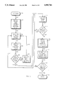
- FIG. 4 is a logic flow diagram of the main program for digitizing the image on the cornea of FIG. 2 by a computer;
- FIGS. 5, 6, 7, and 8 are logic flow diagrams of subroutines utilized in the main program of FIG. 4 including respectively a determination of the edges subroutine; a construction of the line segments subroutine a forming of a matrix subroutine; and a computation of the elevation in formation subroutine;
- FIG. 9 is a schematic diagram showing grid lines displaced on the cornea from an assumed normal position and a trigonometric solution for elevation employed by the present invention.
- FIG. 10 is an illustration showing on the left hand side an orthogonal view of a normal cornea, and on the right hand side the same cornea with the common curve removed which are derived by the display methods used in the present invention.
- FIGS. 11, 12, and 13 are illustrations of contour plots of the cornea derived by the display methods employed in the present invention.
- the invention may be used to obtain through rasterstereographical techniques the topography of an object which is nontransparent and diffusing to light or which is transparent and nondiffusing to light, such as a cornea.
- the invention has particular application but is not limited as a clinical tool for the evaluation of topographic abnormalities of the corneal surface of a patient being a member of the animal kingdom, particularly a human.
- the invention will be described in terms of obtaining the topography of the cornea of a human, but is not limited thereto, and may be employed to determine the surface features or surface contour of an external body portion.
- the invention may also be used in dentistry, particularly in surgery, and also in plastic surgery practices.
- Eyes that are emmetropic and eyes with keratoconus and severe astigmatism can be detected, analyzed and corrected through surgery and contact lenses.
- the invention can be easily used in an examination room or in an operating room.
- limbus is the border or edge of the cornea or clear optical zone and the sclera portion of the eye.
- the sclera is the white, fibrous outer envelope of tissue surrounding the cornea.
- cornea is the transparent anterior portion of the outer fibrous tunic of the eye, a uniformly thick, nearly circular convex structure covering the lens.
- a pixel is an individual picture element constituting a matrix used in a digital computer system for the resolution of images.
- search window applies to a size dimension which denotes how far from a reference line a search for a line segment will take place. Increasing or decreasing a “search window” means to look within a larger or smaller area about the reference line, respectively.
- projection space applies to that area on which the lines are projected, e.g., the cornea.
- image space applies to the several lines as they appear in the computer image.
- the term "fiducial mark” means a mark projected onto the measured surface.
- viewing optics or “imaging optics” are the set of optics through which the camera views the cornea.
- projection optics are the set of optics through which the lines are projected onto the cornea or onto the measured surface.
- the term "diopter” is defined as a unit of curvature and/or of power of lenses, refracting surfaces, and other optical systems.
- FIG. 1a and FIG. 1b show the results of obtaining the corneal topography by the prior art practice of using the placido disk techniques.
- this technique has a placido disk consisting of a series of black and white concentric rings on a circular disk. The disk is placed in front of the eye, and the several rings are reflected by the cornea surface, and their position, size, and spacing in the reflected image are determined by the corneal shape. If the cornea is spherical, the rings appear to be round and regularly shaped as shown particularly in FIG. 1a. If the cornea is oval or astigmatic, the rings appear as being oval and the spacing between the rings varies along the different axes as shown in FIG. 1b. From these photographs it can be seen that much information is not available around the peripheral edges of the white rings in that a shadow is cast by the patient's eyelash, brow or nose.
- FIGS. 2-13 illustrate the present invention.
- a grid is projected onto the cornea surface and is imaged as particularly illustrated in FIG. 2.
- the present invention employ a vertical grid which projects a light and dark line pattern onto the cornea.
- the image of the projected light and dark line pattern on the cornea is in FIG. 2, where one such light line is indicated at 6 and one such dark line is indicated at 8.
- the projected image covers the full cornea including the central optical zone and the limbus, which is the border of the edge of the cornea between the optical zone and the sclera portion of the eye.
- the projected vertical grid which is imaged in FIG. 2 may be obtained through the employment of an apparatus 10 of the invention, which is shown schematically in FIG. 3.
- apparatus 10 of the present invention employs an optical system.
- This optical system consists of an objective lens system 12 associated with a variable magnification turret 14.
- lens system 12 one lens is concave and the other lens is convex. These lenses are used to magnify the cornea.
- the patient preferably places his or her head in a support (not shown) of the apparatus 10 of FIG. 3 so that the cornea 16 of the eye 18 is in line with the optical system.
- two beam splitters shown schematically by a slanted hard line at 20 and 22, and two oculars shown at 24 and 26 for viewing of the cornea 16 by the operator of apparatus 10.
- apparatus 10 of FIG. 3 is a Zeiss or Topcon stereo photo microscope with a slit lamp system, or a similar system thereto which microscope has been modified to support the components of the invention.
- Two cine elbows indicated at 28 and 30 are mounted to the main body portion of apparatus 10 containing the beam splitters 20 and 22. These elbows 28 and 30 are shown to the right and left respectively in FIG. 3.
- elbow 30 contains the slit lamp of a typical microscope which preferably is a Zeiss Model SL-6 or a Topcon model SL-6E presently used in stereobiomicrography.
- Attached to elbow 30 is a video camera 32 which preferably is adapted to produce black and white images.
- Attached to elbow 28 is a coaxial illuminator/flash unit or projection system 34.
- the Zeiss microscope which has generally been used in a general examination of the eye, is modified by the addition of elbows 28 and 30 to support both video camera 32 and projection system 34.
- a grid 36 mounted in front of unit 34 is a grid 36, which is a type of grating consisting only of vertical lines.
- grid 36 is a well-known Rhonchi ruling with a one-to-one ratio of width and space.
- This grid 36 is mounted along the grid projected plane of the optical system of apparatus 10 in order to focus on the cornea at a desired point.
- a filter 38 Interposed between grid 36 and cornea 16 along an optical grid projection pathway is a filter 38.
- This filter 38 preferably is a cobalt blue excitation filter which preferably is a Zeiss SE40 filter.
- a yellow barrier filter 40 which preferably is a Zeiss SB50 filter.
- An infrared cutoff filter 42 which preferably is a Kodak filter, is interposed between grid 36 and the cornea 16 along the grid projection optical pathway.
- Filters 38, 40, and 42 are held in apparatus 10 through holders (not shown) which are adapted to be easily mounted on the body of apparatus 10 for keeping the filters clean, and for preventing the scatter of light illuminated by illuminator/flash unit 34.
- Video camera 32 is connected to an image processor unit 44 which includes a computer. The computer electronically digitizes the projected image on the cornea by the grid 36, and stores and analyzes the data obtained therefrom, more of which is discussed further herein.
- Processor unit 44 is preferably a PAR CTS 100 unit provided by PAR Technology Corporation of New Hartford, N.Y.
- the operator focuses the optical system of apparatus 10.
- ocular 26 is brought into focus by the operator.
- the illumination device on the slit lamp which is normally used for projecting a slit onto the cornea during examination generally is not used in the invention.
- the illuminator/flash unit 34 through cine elbow 28, the beam splitters 22 and 23, and the optical system provide the illumination required for focusing the objective lens system 12 onto the cornea 16.
- the operator of apparatus 10 triggers the illuminator/flash unit 34 which follows the same pathway through the left viewing optics of the optical system of apparatus 10.
- the intensity of illuminator/flash unit 34 provides sufficient intensity to produce an image of the grid 36 projected onto the surface of the cornea 16.
- the invention employs a sodium fluorescein solution which is applied to the external corneal surface to stain the tear film of the eye.
- a sodium fluorescein solution which is commercially available and may be employed is known as Fluress, provided by Barnes Hind which contains 0.25 percent sodium fluorescein.
- Fluress provided by Barnes Hind which contains 0.25 percent sodium fluorescein.
- the light from the flash of unit 34 passes through the cobalt blue filter 38 and the infrared cutoff filter 42.
- the cobalt blue filter 38 causes the fluorescein solution in the tear film on the surface of the eye to fluoresce in an alternating light and dark pattern which is produced by grid 36, and the infrared cutoff filter 42 shields the patient from the infrared transmissions of the flash tube unit 34, which unit 34 may be driven by approximately 400 volts.
- This alternating light and dark line pattern is viewed by the video camera 32 through the yellow barrier filter 40 which as discussed hereinbefore, is used to increase the contrast of this alternating grid pattern.
- An example of this pattern is shown in FIG. 2.
- This image is automatically and electronically digitized and the data is stored and analyzed by image processor unit 44, through a procedure which is explained further with reference to FIGS. 4-13.
- the apparatus 10 of the invention can be used in either an operating room or in an examination room.
- the objective lens 12 will have a focal length of approximately 175 millimeters.
- the angle formed by the plane along the centerline of the apparatus 10 and the projected optical pathway in which grid 36 and projection system 34 is located preferably will be about 6 degrees. This same angle will exist on the left side of apparatus 10 between the centerline and the imaging optical pathway where video camera 32 is located.
- the projection system 34 is spaced 100 millimeters away from cornea 16.
- objective lens 12 will have a focal length of 100 millimeters. This shorter focal length objective will cause the angle between the centerline of apparatus 10 and the projected optical pathway and the angle between the centerline of apparatus 10 and the imaged optical pathway to become wider, i.e., the angle will become greater than the 6 degree angle existing when a 175 millimeter objective lens 12 is used.
- apparatus 10 of FIG. 3 is to be used to determine the topography of a solid object or a nontransparent object which is diffusing to light, then filters 38, 40 and 42 should not be used. Also, it is not necessary to apply the fluorescein solution to the object.
- a feature of the present invention involves applying digital image processing techniques to the projected image of FIG. 2 to find the projected lines and to convert these lines into elevational information. Curvature information for the cornea is then extracted from the elevational information.
- the operator can obtain an intuitive and quantitative assessment of the shape and refractive power of the front surface of the cornea, or of the object under examination.
- the position and spacing of the vertical lines on cornea 16 provide the necessary information for determining the corneal topography.
- the computer of image processing unit 44 through an appropriate program is used to calculate the corneal surface elevation trigonometrically by comparing the horizontal displacement of the grid lines projected onto the cornea to the position of the vertical grid lines when projected onto a two-dimensional flat plane.
- a two-dimensional matrix of elevation points is created.
- the number of data points in a horizontal direction is equal to the number of actual projected grid lines.
- the number of data points in a vertical direction for each grid line is limited only by the resolution of the system of video camera 32.
- a vertical scaling proportional to a horizontal scaling is used.
- surface elevations are calculated on a full cornea and the sclera.
- the sclera is the white, fibrous outer envelope of tissue surrounding the cornea.
- FIG. 2 it is apparent that the cornea covering the pupil and the iris is completely represented with the sclera surrounding the cornea around its periphery which is substantially darkened in FIG. 2.
- the grid lines of FIG. 2 vary in shape and intensity.
- the cornea was made opaque by topically applying the fluorescein solution onto the outer surface of the cornea, and the grid 36, through the cobalt blue filter 38, was projected onto the eye 18.
- the spacing between horizontal points for the two-dimensional matrix is approximately 0.4 millimeters. If desired, a higher magnification can be used, reducing this distance to 0.1 millimeters.
- the resultant matrix size then is approximately 45 horizontal data points by 60 vertical data points for a total greater than 2500 elevation points across the surface of the cornea.
- the software for the image processing unit 44 is illustrated in terms of flow diagrams in FIGS. 4-8.
- the main software program for determining the topography of the surface of a cornea is illustrated in FIG. 4 and is written in terms of subroutines, the flow diagrams for which are shown in FIGS. 5-8.
- These computer programs have been developed (a) to identify the grid lines, (b) to calculate the elevation points from which curvature information is derived which has been discussed to some length hereinbefore, and (c) to display the results.
- the main software program of processing unit 44 of FIG. 3 sets forth several directives for performing steps (a), (b), and (c) in the preceding paragraph.
- the first step is to obtain the data of, for instance, the imaged grid lines on the cornea of FIG. 2. This step of obtaining this data is indicated at 46.
- the imaged grid lines are those that appear in the computer image.
- the processing unit 44 employs the first subroutine indicated at 50 and identified as "DET EDGES". As is apparent, this subroutine finds the edges of the imaged grid lines on the cornea. From this the main program moves down as indicated at 52 to the next subroutine indicated at 54, and entitled “LINE SEGS”. This subroutine is designed to construct a line segment from the edge points found in the subroutine "DET EDGES".
- the main program moves down as indicated at 56 to the subroutine entitled "BUILD MAT" indicated at 58.
- This subroutine is designed to link the line segments together to form a matrix of contiguous lines.
- two additional steps indicated by numbers 60, 62, 64, and 66 are performed by processing unit 44.
- the first step indicated at 62 is referred to as "REF LINE”.
- This step finds the reference line in the projection space.
- a correction for the distortion in the optics and in the projection grid lines is found by the step indicated at 66 and is referred to as "CORRECT".
- This subroutine is designed to compute the elevation of the imaged grid lines from the line positions found by the previous subroutine.
- This subroutine "COMP ELEV” is followed as indicated at 72 by the subroutine indicated at 74 entitled “COMP CUR”.
- This "COMP CUR" subroutine is designed to compute the curvature information of the cornea from the elevation data obtained in the subroutine "COMP ELEV”.
- the subroutine for computing the curvature is not disclosed herein but is indicated as being a preferred step in the invention.
- the method preferably used in the invention for calculating the radius of curvature is the simplex computer algorithm to best fit an arc to the elevation points. This simplex algorithm is well-known in the computer industry where software is readily available.
- the main program of FIG. 4 is exited, and the processing unit 44 through a display device (not shown) visualizes the results of the algorithm of FIG. 4, as shown for instance in FIGS. 10, 11, 12, and 13, more of which is to be discussed hereinafter along with more details of the several subroutines of FIGS. 5, 6, 7, and 8.
- the first subroutine "DET EDGES" is called up by the main program to determine the edges of the imaged lines. At this time the lines of the vertical grid 36 projected onto the cornea are visible in the digitized image.
- This subroutine of FIG. 5 is designed to attempt to find the edges of the projected lines of every third row of the image.
- This algorithm of FIG. 5 uses the wave-like distribution of pixel intensities related to the light to dark transition of the lines to find the near exact center of each line.
- the subroutine of FIG. 5 illustrates the several steps involved in accomplishing this.
- the first step as indicated at 82 and 84 is to use a 3 ⁇ 3 convolution kernel to perform a standard image averaging on the whole image.
- the second step as indicated at 86 and 88 is to center a 1 ⁇ N window on a pixel in the image.
- the third step as indicated at 90 and 92 is to determine the range of the pixel intensities in the window. This is accomplished by looking at the numeric pixel intensities of the pixels in the window for the lowest and the highest values. These values mark the range.
- the next step is to determine if the pixel is in the upper half of the intensity range.
- the pixel is considered to be an edge point. This edge point is added to a temporary point array. As indicated at 110, from the step in block 100, the subroutine goes back to block 88 where these steps are repeated for the next pixel in the image. If the pixel under study is not in the upper half of the intensity range, then as indicated at 112 and 114 the pixel is not considered to be an edge point.
- the next step is to ask whether there are any edge points in the temporary array. This is indicated at 116 and 118. If the answer is "no,” then as indicated at 120 and 122 the subroutine returns to block 88 to examine the next pixel in the image. If the answer is "yes,” then as indicated at 124 and 126 the program proceeds to the step entitled "EDG APEX".
- This algorithm in FIG. 5 finds the center of the line formed by the points in the temporary array by fitting a curve to the pixel intensities of the edge points. As numbers 128 and 130 indicate the center point is added to the line point array, and the edge points are removed from the temporary array. The final step is indicated at 132 and 134 where it is determined as to whether all the pixels in the image have been examined.
- the flow diagram of the subroutine of FIG. 6 is identified as "LINE SEG", and is used to construct line segments from the line points. This portion of the main program is activated when all the line points of the lines of every third row of the image have been found by the subroutine of FIG. 5.
- This algorithm of FIG. 6 attempts to link the several line points to form a series of continuous line segments. In order to account for possible noise from not being included, restrictions are applied when linking the line points.
- a root line point is found.
- a search window is specified in which the search is made. This limits the possibility of incorrect line points being linked to form a line segment.
- a length restriction is applied to discard those line segments which may have been inadvertently created. Referring specifically to FIG. 6, the flow diagram of this subroutine illustrates the several steps involved in forming the line segment forming operation.
- the first step as indicated at 140 and 142 is to ask whether all the unlinked line points in the image have been examined as specifically shown in block 142. If “yes,” then the subroutine returns to the main program of FIG. 4 as indicated by numbers 144 and 146. If “no,” a further search is made vertically within a 1 ⁇ M window for neighboring line points as indicated at 148 and 150. The question “Is a line point found?" is asked as indicated at 152 and 154. If a line point is found, the line point is added to a temporary line point array as indicated at 156 and 158.
- the next step from the step at 158 is to position the 1 ⁇ M search window over the newly found line point and to find other line points linked to the newly found or root line point by a continuous search as indicated at 160 and 162. From 162, the subroutine by line 163 returns to block 150. If no line point is found by the step at 154 then as indicated at 164 the question is asked at 166 as to whether the line segment is long enough.
- the algorithm of FIG. 6 is designed to check the length of the line segment formed by the found line points followed by asking the question indicated at 166. If “no,” then all the line points in the line segment are removed from the line point array as indicated at 172 and 174, and the subroutine returns to 142 to the beginning of this loop as indicated at 176. If “yes,” then as indicated at 178 and 180 the line points in the line segment are marked as being included.
- one of the final steps is to add the line segment to the array of line segments. From this step, the algorithm returns as indicated at 186 to the beginning of the subroutine at 142. If certain conditions are met, this algorithm is completed and the operation is returned to the main program of FIG. 4.
- the next step is to link the line segments to form a matrix of contiguous lines.
- the subroutine of FIG. 7 illustrates the several steps for performing this operation. These contiguous lines are referenced relative to each other in order to determine their position on the cornea.
- This process involves first finding the longest line determined in the "Line Seg” subroutine of FIG. 6. This line is used as a reference line.
- the subroutine of FIG. 7 entitled “Build Mat” looks horizontally to find the next vertical line segment. The search is for each line point in the reference line segment constrained within a search window. If a line segment is not found within the allowed range then there is no data next to the reference line at this line point position. The search continues for every line point in the reference line. Once all the line points in the reference line have been searched, a second test for line point validity is applied. The average spacing between the reference line and the newly found line is computed.
- This procedure for the reference line is then repeated for the newly found line which then becomes the reference line.
- the search window is also changed from the previous dimension to 1.5 times the average spacing which has just been computed.
- the search window is a size dimension which denotes how far from the reference line a search for a line segment will take place. Increasing or decreasing the search window means to look within a larger or smaller area about the reference line respectively.
- the final output of the subroutine of FIG. 7 is a two-dimensional array of image positions denoting the points of the located lines.
- the subroutine of FIG. 7 continues to reference line segments starting at the first reference line and proceeding to the left side of the image until the left side of the image is reached.
- the subroutine then returns to the original reference line and repeats the same process but this time moving to the right side of the image.
- all the line segments have either been linked to form continuous lines or have been discarded.
- the several steps involved for the final output are shown in the algorithm of FIG. 7.
- the first step is to find the longest line segment and to label it as the reference line as indicated at 190 and 192.
- the next step is to make a search in a specified direction within a 1 ⁇ N dimension search window for a neighboring line segment as indicated at 194 and 196. From this, the next step as indicated at 198 and 200 is to ask whether a line segment is found.
- the search is advanced to the next point in the reference line from 212. From 212, the algorithm returns to the step of 196 as indicated at 214. If "yes,” then as indicated at 216 and 218 the search is advanced down the line equivalent to the length of the found line segment.
- next step is to then ask whether the end of the reference line is met as indicated at 220 and 222. If “no,” the subroutine returns as indicated by 224 to the beginning of the main loop of this subroutine to continue the search by the step at 196. If “yes,” the next step is to remove any line points in the found line that produce “spikes” or deviations from the found line as indicated at 226 and 228.
- the next question as indicated at 230 and 232 in FIG. 7 is to ask whether the margin of the image has been met. If “no,” then as indicated at 234 the subroutine by way of line 236 returns to the beginning of the main loop to continue the search by the step at 196. If “yes,” the next step is to ask if the margin is the appropriate one as indicated at 238 and 240. If the answer is "yes,” the subroutine as indicated at 242 and 244 returns to the main program of FIG. 4. If the answer is "no,” the directive is given to change the specified search direction from left to right as indicated at 246 and 250, and the subroutine is returned as indicated by line 236 to the beginning of the main loop to continue the search by the step at 196.
- Steps 62 and 66 of the main program of FIG. 4 indicate the two additional processes which are preferably completed before the subroutine of FIG. 8 is employed.
- Step 62 the next process is to find the reference line found in the "BUILD MAT" subroutine in the projection space.
- the projection space as defined is the cornea onto where the lines are projected.
- This preceding step is done in order to calculate the correct elevation and to perform correction for distortion.
- the system locates a fiducial mark which is regarded as a standard of reference on one of the lines. The position of this line in the projection space is known and from this known position all the remaining lines are referenced to the projection space.
- a fiducial mark is formed by introducing a ⁇ break ⁇ in one of the lines in the grid used to form the projected lines. If the lines are focused properly onto the cornea, the break in the line will appear at a specific set location in the image The "BUILD MAT" subroutine of FIG. 7 will check this known location against the location of holes that have been found If no hole has been found at this location the lines were not focused properly. The operator of apparatus 10 is informed of this and he or she must take another picture to process.
- this fiducial mark position is known at optimum focus on the cornea, it is also known at optimum focus on a flat plane. Since all lines are referenced to each other, and, in turn the fiducial mark, the actual displacement of each line from its actual position on a flat plane can be determined.
- the step in No. 66 provides for a correction for any distortion in the optic system and in the projected grid 36 of apparatus 10. Since the optics and the grid 36 are not ideal, there will be inevitably some distortion and imperfections in the system. In order to assure accuracy, this must be corrected.
- the lines shifted is the number of grid lines which are either positive or negative from the reference line to the line to be measured
- SP is the grid spacing constant as projected onto the flat plane
- HD is the horizontal distance measured along a horizontal of the flat plane from the reference point to the point on the line to be measured.
- the elevation information is determined according to the subroutine of FIG. 8 having the heading "COMP ELEV".
- the operation of this subroutine involves knowing the geometry of the optical system and the video camera 32 used in the imaging procedure performed by apparatus 10 of the invention.
- One of the important steps for computing the elevation of the points is to determine the equation of the plane formed by the grid line.
- the equation of the plane formed by the grid line is determined by a calibration step. This step involves projecting the lines onto a flat surface. The lines are then detected and referenced as stated hereinbefore. For each vertical line two points on the line are used. One point is from the upper half of the line and the other point is from the lower half of the line.
- the focal length of the optics focal length of a standard C-mount adaptor is 35 millimeters
- the distance between the stereo optical pathways and the focal length of the objective lens 12 of the optical system to a ⁇ ray ⁇ for each point can be calculated using standard vector mathematics and standard ⁇ pin-hole camera ⁇ geometric principles.
- the equation for the plane can be found by computing the vector cross product of the two vectors. This is performed for each vertical line and is stored in a file in the computer. This file is retrieved whenever a measurement is made.
- the next step is to determine the equation of the ray formed by each point in the imaged lines. This is performed for each line point in each line found projected onto the corneal surface. This produces a ray for each line point in the line. The ray representing the point in the line and the plane of the line are solved simultaneously to determine the point of intersection. This is done using standard ray/plane intersection vector mathematics, the methods of which are outlined in standard analytical geometry textbooks.
- the final result or output is a two dimensional array of elevation information for the front surface of the cornea which, in fact, is the topography of the front surface of the cornea.
- the subroutine of FIG. 8 shows the several steps involved in computing the elevational information, as described hereinabove.
- the first step as indicated at 252 and 254 is to find the reference line of the projection space in the image.
- the equation for the plane formed by the projected grid line is looked up as indicated at 256, 258, 260 and 262.
- the equation for the ray formed by the point on the line in the image is computed.
- the next step as indicated at 272 and 274 is to compute the simultaneous solution of both the ray and the plane equations in order to obtain the elevation at that point.
- the next step is to inquire as to whether the elevations for all the points in the grid line have been found as indicated at 276 and 278. If “no,” the subroutine as indicated at 280 returns to 266 which forms an inner loop which produces this result for each point in the vertical grid line. If the answer is "yes,” the next inquiry as indicated at 282 and 284 is whether the elevation for all the grid lines has been found. If “no,” the subroutine as indicated at 286 returns to 258 forming the main outer loop for this subroutine. If "yes,” the subroutine returns to the main program of FIG. 4 as indicated at 288 and 290.
- FIG. 9 there is illustrated the projected grid lines onto the cornea, and a normal positioning and a deviated positioning for the lines.
- the matrix point elevations that are calculated from the grid line in the immediately preceding sentence are also moved proportionately to the left.
- Equation No. 2 The relationship between line movement and elevation change is denoted by Equation No. 2 which is derived from FIG. 9:
- ⁇ angle between the imaging pathway and the projection pathway
- a two-dimensional array of elevation information is obtained by the flow diagram of the subroutine of FIG. 8. This matrix can then be stored for future use or processed for further image analysis, including computing the curvature information of the cornea.
- the subroutine as indicated at 72 and 74 of FIG. 4 entitled "COMP CUR" performs the function for obtaining the curvature information.
- the elevation information is converted into curvature information by any of the well-known methods for fitting curves to data.
- the fitting of a curve to data is done by a simplex algorithm method, which is set forth in a standard math textbook.
- the simplex algorithm may preferably be a computer program easily available in the computer industry.
- the computer of processing unit 44 displays a cross sectional view of the cornea along any axis by plotting the elevation points of the matrix along any particular line. The radius of curvature is calculated using the same method.
- Curvatures can be determined for any axis either for the average across the full cornea or for a small portion of it.
- the final step is to write out the values and to return this subroutine to the main program of FIG. 4 in order to produce the desired displays similar to that shown in FIGS. 10-13.
- an image of the cornea can be represented in several forms, some of which are demonstrated in FIGS. 10, 11, 12, and 13.
- Standard graphics processing techniques which are known in the computer industry can be used to rotate the cornea around the X or the Y axis.
- the left portion of FIG. 10 shows an orthogonal view of a normal cornea rotated 80 degrees to the right to view the shape of the cornea across the bridge of the nose.
- the right portion of FIG. 10 shows the same cornea from the same angle, but the common curve of the cornea has been subtracted out to accentuate distortions from a spherical shape.
- Contour plots of the cornea are also shown in FIGS. 11, 12, and 13.
- each line on the plot represents an area of equal height.
- each line represents an elevation change of 0.1 millimeters.
- the image of FIG. 11 is magnified 2.5 times to obtain the data for FIG. 12.
- Each contour line in FIG. 12 represents 0.0125 millimeters in elevation.
- FIGS. 11 and 12 illustrate that the topography of a portion of the cornea represented therein is substantially curved.
- FIG. 13 illustrates a full cornea of a patient with astigmatism, where the circles of the contour plot illustrate a substantially flatter topography for the cornea in the horizontal plane.
- the system of the present invention comprising the apparatus 10 of FIG. 3 and the main program of FIG. 4 was calibrated using four steel balls of varying diameters as a standard for measuring curvature. The balls were sprayed with paint to provide a non-reflective surface and then measured with a micrometer.
- each ball was photographed a total of four times. The images were processed to find a radius of curvature.
- the average error of the sixteen measurements was 0.060 millimeters with a range of +0.11 to -0.16 millimeters.
- the system of the present invention tended to overestimate the true curvature, while for the smallest diameter ball, the system tended to underestimate the true curvature of the ball.
- the measurements were approximately 0.10 millimeters or less. This calibration technique for obtaining a measurement for curvature is familiar to those skilled in the art.
- the accuracy of the method of the invention is dependent on several variables. These variables are: the resolution of video camera 32; the magnification of variable magnification turret 14; the angle ⁇ , between the projected image and the viewing optics; and the number of projected lines of grid 36. As the magnification of the corneal image increases, or the resolution of the video camera 32 increases, the change in depth represented by each pixel is reduced, thereby increasing the accuracy of the measured displacement of the lines of grid 36.
- the computer would then measure the change in the line position more precisely and, thus measure the elevation more precisely.
- the sensitivity between the movement of the line and the change in elevation does not change.
- the same h equals a larger z, i.e., the same line displacement equals more elevational change.
- the ability to increase the angle is limited by the curvature of the cornea. If the angle is too large, the imaging side of the cornea will be completely shadowed by the cornea itself, and no lines will be projected onto that side of the cornea. With normal corneal curvature of 7.0 mm taken into account, the angle can be increased up to about 40 degrees with little or no problems in the efficiency of the system of the invention.
- the accuracy of the measurement of the topography of the cornea is proportional to the angle of separation between the projected image and the viewing or imaging optics.
- the viewing or imaging optics are the set of optics in apparatus 10 through which the video camera 32 views the cornea 16.
- the projection optics are the set of optics in apparatus 10 through which the lines are projected onto the cornea 16 or onto a measured surface. As the angle of separation between grid 36 and video camera 32 increases, so does the sine of the angle, which angle is used to determine the elevation of the surface of the cornea, making the depth represented by a one-pixel change in displacement of the grid lines smaller as already discussed herein.
- Increasing the number of lines projected onto the cornea could easily be done by changing the grid 36 of projection system 34 of FIG. 3. Doubling the number of the grid lines would result in an increase in the number of elevation points in the formed matrix. For example, the 2500 points of the example given hereinabove would be increased to approximately 10,000 elevation points across the corneal surface.
- the invention utilizes the optics of a Zeiss microscope with a slit lamp (FIG. 3) for projection of the grid and for the acquisition of the projected image.
- the video camera 32 and the projection system 34 mounted on elbows 28, 30 are used with a beam splitter 20, 22.
- curvature information of the cornea is obtained. It is to be appreciated to those skilled in the art that from the elevational information, the diopter power of the cornea can also be obtained.
- elbows 28, 30 adapt easily to a Zeiss or Topcon microscope. This adaptation enhances its use in an operating room in that images on the cornea are easily and quickly attainable intraoperatively without cumbersome attachments.
- the obtained data for the corneal surface is quickly processed and the results are instantly available.
- the projection system operates in approximately 1/1000th of a second and the recording system operates in approximately 1/30 of a second.
- the entire process for producing an image and obtaining the results of an image may be accomplished within about one to three minutes by the invention, whereas present techniques for obtaining the topography of a cornea may take as much as twenty to thirty minutes.
- the present invention provides an effective, quick and efficient means and method for more accurately determining the topography of a cornea of a patient in either an operating room, in an examination room or in a clinic by using rasterstereographical principles combined with an image processing unit which automatically digitizes the gridlines of a projected image through computer software. This is accomplished by causing a grid to be actually projected onto the cornea instead of the grid being reflected off the cornea which is a transparent nondiffusing member.
- the system, the method, and the apparatus of the invention may be employed to derive information of the cornea of any species of the animal kingdom. Furthermore, the present invention may be used to more accurately determine the topography of any object which is transparent, nondiffusing, such as a cornea, or which is not transparent and diffusing, such as external body portions, and in some instances mandible portion where dentistry surgery is concerned. In the latter instance, it is not necessary to use the filters 38, 40, and 42, nor the fluorescein solution.
Abstract
Description
Deviation of Grid=(Lines shifted×SP)-HD,
z=cosβ×h/sinα
Claims (50)
z=(cosβ×h)/sin α
Deviation of grid=(lines shifts×SP)-HD;
Z=(cos β×h)/sinα
Deviation of grid=(lines shifted×SP)-HD,
Priority Applications (3)
| Application Number | Priority Date | Filing Date | Title |
|---|---|---|---|
| US07/321,252 US4995716A (en) | 1989-03-09 | 1989-03-09 | Method and apparatus for obtaining the topography of an object |
| AU51187/90A AU634757B2 (en) | 1989-03-09 | 1990-03-08 | Method and apparatus for obtaining the topography of an object |
| US07/562,481 US5159361A (en) | 1989-03-09 | 1990-08-03 | Method and apparatus for obtaining the topography of an object |
Applications Claiming Priority (1)
| Application Number | Priority Date | Filing Date | Title |
|---|---|---|---|
| US07/321,252 US4995716A (en) | 1989-03-09 | 1989-03-09 | Method and apparatus for obtaining the topography of an object |
Related Child Applications (1)
| Application Number | Title | Priority Date | Filing Date |
|---|---|---|---|
| US07/562,481 Continuation-In-Part US5159361A (en) | 1989-03-09 | 1990-08-03 | Method and apparatus for obtaining the topography of an object |
Publications (1)
| Publication Number | Publication Date |
|---|---|
| US4995716A true US4995716A (en) | 1991-02-26 |
Family
ID=23249826
Family Applications (1)
| Application Number | Title | Priority Date | Filing Date |
|---|---|---|---|
| US07/321,252 Expired - Lifetime US4995716A (en) | 1989-03-09 | 1989-03-09 | Method and apparatus for obtaining the topography of an object |
Country Status (2)
| Country | Link |
|---|---|
| US (1) | US4995716A (en) |
| AU (1) | AU634757B2 (en) |
Cited By (86)
| Publication number | Priority date | Publication date | Assignee | Title |
|---|---|---|---|---|
| WO1993021818A1 (en) * | 1992-05-01 | 1993-11-11 | Summit Technology, Inc. | Method and system for topograhic measurement |
| WO1993024049A1 (en) * | 1992-06-02 | 1993-12-09 | Eyesys Laboratories | Checkered placido apparatus and method |
| US5357294A (en) * | 1992-07-13 | 1994-10-18 | Kimiya Shimizu | Method for displaying optical properties of corneas |
| US5517261A (en) * | 1994-12-13 | 1996-05-14 | Alcon Laboratories, Inc. | Focusing method for a corneal topographer |
| US5526072A (en) * | 1993-04-14 | 1996-06-11 | Alcon Laboratories, Inc. | Apparatus and technique for automatic centering and focusing a corneal topographer |
| WO1997042609A1 (en) * | 1996-05-07 | 1997-11-13 | Synthonics Incorporated | Methods and apparatus for creation of three-dimensional wire frames and for three-dimensional stereo morphing |
| WO1997043006A1 (en) | 1996-05-13 | 1997-11-20 | Par Technology Corporation | Simulating corneal laser surgery |
| US5742291A (en) * | 1995-05-09 | 1998-04-21 | Synthonics Incorporated | Method and apparatus for creation of three-dimensional wire frames |
| US5796859A (en) * | 1991-10-08 | 1998-08-18 | Computed Anatomy Incorporated | Processing of keratoscopic images employing local spatial phase |
| US5818957A (en) * | 1991-10-08 | 1998-10-06 | Computed Anatomy Incorporated | Processing of keratoscopic images |
| US5841511A (en) * | 1992-06-02 | 1998-11-24 | Eyesys Technologies, Inc. | Method of corneal analysis using a checkered placido apparatus |
| WO1998053881A1 (en) | 1997-05-27 | 1998-12-03 | Visx, Incorporated | Systems and methods for imaging corneal profiles |
| US5864383A (en) * | 1997-04-24 | 1999-01-26 | Orbtek, Inc. | Single-curvature placido plate |
| US5867250A (en) * | 1996-05-03 | 1999-02-02 | Baron; William S. | Apparatus and method for optically mapping front and back surface topographies of an object |
| US5909271A (en) * | 1997-10-24 | 1999-06-01 | Computed Anatomy, Incorporated | Device for performing ophthalmic procedures with improved alignment |
| US5988815A (en) * | 1997-10-24 | 1999-11-23 | Tomey Co., Ltd. | Pattern illumination device |
| US6024449A (en) * | 1998-07-13 | 2000-02-15 | Smith; Robert F. | High speed topography measurement of semi-diffuse objects |
| WO2000010449A1 (en) | 1998-08-20 | 2000-03-02 | Bioshape Ag | Device for determining the surface shape of biological tissue |
| US6079831A (en) * | 1997-04-24 | 2000-06-27 | Orbtek, Inc. | Device and method for mapping the topography of an eye using elevation measurements in combination with slope measurements |
| EP1034756A2 (en) | 1999-03-10 | 2000-09-13 | Luis Antonio Ruiz, M.D. | Interactive corrective laser eye surgery system |
| WO2001028476A1 (en) | 1999-10-21 | 2001-04-26 | Technolas Gmbh Ophthalmologische Systeme | Iris recognition and tracking for optical treatment |
| WO2001028410A1 (en) | 1999-10-21 | 2001-04-26 | Technolas Gmbh Ophthalmologische Systeme | Customized corneal profiling |
| US6454761B1 (en) * | 1995-01-30 | 2002-09-24 | Philip D. Freedman | Laser surgery device and method |
| WO2003015660A2 (en) | 2001-08-17 | 2003-02-27 | West Virginia University | Non-invasive ocular assessment method and associated apparatus |
| US20030072570A1 (en) * | 2001-10-12 | 2003-04-17 | Pentax Corporation | Stereo camera and automatic convergence adjusting device |
| WO2003034910A1 (en) * | 2000-10-18 | 2003-05-01 | Lasersight Technologies, Inc. | Stereo view reflection corneal topography |
| US6592574B1 (en) | 1999-07-28 | 2003-07-15 | Visx, Incorporated | Hydration and topography tissue measurements for laser sculpting |
| US6626537B1 (en) | 2001-05-18 | 2003-09-30 | West Virginia University | Non-invasive ocular dynamic monitoring assessment method and associated apparatus |
| WO2003105722A2 (en) | 2002-06-13 | 2003-12-24 | Visx, Incorporated | Corneal topography-based target warping |
| US20040024389A1 (en) * | 2000-09-15 | 2004-02-05 | D'ippolito Giuseppe | Apparatus for determining and ablating the corneal tissue volume necessary for performing a corneal lamellar grafting operation |
| US20040027537A1 (en) * | 2002-05-24 | 2004-02-12 | Sarver Edwin J. | Continuous two-dimensional corneal topography target |
| US6692126B1 (en) | 2001-10-17 | 2004-02-17 | Carl Zeiss Meditec, Inc. | Method and apparatus for measuring a corneal profile of an eye |
| US6766042B2 (en) | 2001-04-26 | 2004-07-20 | Memphis Eye & Contact Associates | System to automatically detect eye corneal striae |
| US6810369B1 (en) * | 1998-07-03 | 2004-10-26 | Treuhandbüro Dr. Ottiker + Partner AG | Method for the computer-assisted production of a machine with geometrically-predetermined spherical components |
| US20040263785A1 (en) * | 2003-06-16 | 2004-12-30 | Visx, Inc. | Methods and devices for registering optical measurement datasets of an optical system |
| US6888640B2 (en) | 2000-02-04 | 2005-05-03 | Mario J. Spina | Body spatial dimension mapper |
| US20050174537A1 (en) * | 2003-10-24 | 2005-08-11 | Nevyas Herbert J. | Ophthalmic operative keratometer with movable fixation/centration device |
| US20050185138A1 (en) * | 2004-02-19 | 2005-08-25 | Visx, Incorporated | Methods and systems for differentiating left and right eye images |
| US20050213031A1 (en) * | 2004-02-25 | 2005-09-29 | Meyers William E | Method for determining corneal characteristics used in the design of a lens for corneal reshaping |
| US20050243276A1 (en) * | 2004-04-20 | 2005-11-03 | Wavetec Vision Systems, Inc. | Integrated surgical microscope and wavefront sensor |
| US20070195268A1 (en) * | 2006-02-14 | 2007-08-23 | Sarver Edwin J | Advanced corneal topography system |
| US20080018856A1 (en) * | 2006-02-14 | 2008-01-24 | Vision Optimization, Llc | Corneo-scleral topography system |
| US20080204659A1 (en) * | 2007-02-27 | 2008-08-28 | Carbonari Kenneth J | Placido Projector for Corneal Topography System |
| US7431457B2 (en) | 2002-05-30 | 2008-10-07 | Amo Manufacturing Usa, Llc | Methods and systems for tracking a torsional orientation and position of an eye |
| DE102007017611A1 (en) | 2007-04-12 | 2008-10-16 | SCHRÜNDER, Stephan | Method and system for eye measurement |
| US20080259276A1 (en) * | 2005-10-31 | 2008-10-23 | Crs & Associates | Method and Apparatus For Measuring the Deformation Characteristics of an Object |
| US20080291532A1 (en) * | 2007-05-26 | 2008-11-27 | James Jianguo Xu | 3-d optical microscope |
| US20080291533A1 (en) * | 2007-05-26 | 2008-11-27 | James Jianguo Xu | Illuminator for a 3-d optical microscope |
| US20090033940A1 (en) * | 2007-08-03 | 2009-02-05 | Siemens Medical Solutions Usa, Inc. | Multi-Level Light Curtain With Structure Light Sources and Imaging Sensors |
| US20090238470A1 (en) * | 2008-03-24 | 2009-09-24 | Ives Neil A | Adaptive membrane shape deformation system |
| US20090316112A1 (en) * | 2008-04-04 | 2009-12-24 | Amo Wavefront Sciences, Llc | Method for registering multiple data sets |
| US20100042210A1 (en) * | 2003-04-10 | 2010-02-18 | Tsontcho Ianchulev | Intraoperative Estimation of Intraocular Lens Power |
| US20100182568A1 (en) * | 2009-01-21 | 2010-07-22 | Sarver Edwin J | Continuous two-dimensional corneal topography target |
| US20100217278A1 (en) * | 2009-02-20 | 2010-08-26 | Ashok Burton Tripathi | Real-time surgical reference indicium apparatus and methods for intraocular lens implantation |
| US20100238408A1 (en) * | 2006-02-14 | 2010-09-23 | Vision Optimization, Llc | Method and apparatus for determining dynamic deformation characteristics of an object |
| US20110007270A1 (en) * | 2009-07-06 | 2011-01-13 | Wavetec Vision Systems Inc. | Objective quality metric for ocular wavefront measurements |
| US20110015541A1 (en) * | 2009-07-14 | 2011-01-20 | Wavetec Vision Systems, Inc. | Determination of the effective lens position of an intraocular lens using aphakic refractive power |
| US20110149239A1 (en) * | 2009-12-22 | 2011-06-23 | Amo Wavefront Sciences, Llc | Optical diagnosis using measurement sequence |
| CN103115585A (en) * | 2013-01-29 | 2013-05-22 | 哈尔滨工业大学 | Method and device for fluorescence interference microscopic measurement based on stimulated radiation |
| WO2013082466A1 (en) | 2011-11-30 | 2013-06-06 | Amo Development, Llc. | System and method for ophthalmic surface measurements based on sequential estimates |
| US8545023B2 (en) | 2009-07-14 | 2013-10-01 | Wavetec Vision Systems, Inc. | Ophthalmic surgery measurement system |
| US8550624B2 (en) | 2008-11-06 | 2013-10-08 | Wavetec Vision Systems, Inc. | Optical angular measurement system for ophthalmic applications and method for positioning of a toric intraocular lens with increased accuracy |
| US20130315489A1 (en) * | 2012-05-22 | 2013-11-28 | Ricoh Company, Ltd. | Pattern processing device, pattern processing method, and pattern processing program |
| US8619405B2 (en) | 2007-10-31 | 2013-12-31 | Wavetec Vision Systems, Inc. | Wavefront sensor |
| US20140098342A1 (en) * | 2011-11-04 | 2014-04-10 | The General Hospital Corporation | System and method for corneal irradiation |
| US20150002814A1 (en) * | 2013-06-28 | 2015-01-01 | Carl Zeiss Ag | Microscopy System and Method for Imaging Phase Objects |
| US20150085254A1 (en) * | 2013-09-26 | 2015-03-26 | Topcon Medical Laser Systems, Inc. | Micro-Display Based Slit Lamp Illumination System |
| US20150157198A1 (en) * | 2013-12-11 | 2015-06-11 | Topcon Medical Laser Systems, Inc. | Ophthalmic Illumination System with Micro-Display Overlaid Image Source |
| US9072462B2 (en) | 2012-09-27 | 2015-07-07 | Wavetec Vision Systems, Inc. | Geometric optical power measurement device |
| US9402366B2 (en) | 2007-05-17 | 2016-08-02 | Amo Development, Llc | Customized laser epithelial ablation systems and methods |
| US9552660B2 (en) | 2012-08-30 | 2017-01-24 | Truevision Systems, Inc. | Imaging system and methods displaying a fused multidimensional reconstructed image |
| US20170181626A1 (en) * | 2015-12-23 | 2017-06-29 | Industrial Technology Research Institute | Introcular pressure detecting device and detecting method thereof |
| WO2018031812A1 (en) | 2016-08-10 | 2018-02-15 | Amo Development, Llc | Epithelial ablation systems and methods |
| US10117721B2 (en) | 2008-10-10 | 2018-11-06 | Truevision Systems, Inc. | Real-time surgical reference guides and methods for surgical applications |
| US10209501B2 (en) | 2010-07-23 | 2019-02-19 | Kla-Tencor Corporation | 3D microscope and methods of measuring patterned substrates |
| US10299880B2 (en) | 2017-04-24 | 2019-05-28 | Truevision Systems, Inc. | Stereoscopic visualization camera and platform |
| CN110074754A (en) * | 2018-01-25 | 2019-08-02 | 哈格-斯特莱特有限公司 | Check the device of eyes |
| US10398598B2 (en) | 2008-04-04 | 2019-09-03 | Truevision Systems, Inc. | Apparatus and methods for performing enhanced visually directed procedures under low ambient light conditions |
| US10762348B2 (en) * | 2015-06-29 | 2020-09-01 | Precitec Optronik Gmbh | Method and apparatus for determining the position and/or the orientation of an eye |
| US10917543B2 (en) | 2017-04-24 | 2021-02-09 | Alcon Inc. | Stereoscopic visualization camera and integrated robotics platform |
| US11051884B2 (en) | 2008-10-10 | 2021-07-06 | Alcon, Inc. | Real-time surgical reference indicium apparatus and methods for surgical applications |
| CN113208558A (en) * | 2021-04-30 | 2021-08-06 | 南昌虚拟现实研究院股份有限公司 | Eyeball tracking method and device, electronic equipment and storage medium |
| US11083537B2 (en) | 2017-04-24 | 2021-08-10 | Alcon Inc. | Stereoscopic camera with fluorescence visualization |
| US11116663B2 (en) | 2018-01-19 | 2021-09-14 | Iridex Corporation | System and method for a patient-invisible laser treatment alignment pattern in ophthalmic photomedicine |
| CN114587268A (en) * | 2022-04-06 | 2022-06-07 | 上海观爱医疗科技有限公司 | Full-automatic optometry topographic map instrument and optometry method |
| CN114729800A (en) * | 2019-11-29 | 2022-07-08 | 日立安斯泰莫株式会社 | Surface inspection apparatus, shape correction apparatus, surface inspection method, and shape correction method |
Citations (2)
| Publication number | Priority date | Publication date | Assignee | Title |
|---|---|---|---|---|
| US3169459A (en) * | 1963-03-11 | 1965-02-16 | Michael A Friedberg | Method of determining surface contours of an eye |
| US4685140A (en) * | 1984-06-26 | 1987-08-04 | Kera Corporation | Keratograph autoscanner system |
Family Cites Families (1)
| Publication number | Priority date | Publication date | Assignee | Title |
|---|---|---|---|---|
| JPS5875531A (en) * | 1981-10-28 | 1983-05-07 | 株式会社トプコン | Apparatus for measuring curvature |
-
1989
- 1989-03-09 US US07/321,252 patent/US4995716A/en not_active Expired - Lifetime
-
1990
- 1990-03-08 AU AU51187/90A patent/AU634757B2/en not_active Expired
Patent Citations (2)
| Publication number | Priority date | Publication date | Assignee | Title |
|---|---|---|---|---|
| US3169459A (en) * | 1963-03-11 | 1965-02-16 | Michael A Friedberg | Method of determining surface contours of an eye |
| US4685140A (en) * | 1984-06-26 | 1987-08-04 | Kera Corporation | Keratograph autoscanner system |
Non-Patent Citations (38)
| Title |
|---|
| Carsten Edmund and Erik Sjontoft, "The Central-Peripheral Radius of the Normal Corneal Curvature,"Acta Ophthalmologica, (1985), vol. 63, pp. 670-677. |
| Carsten Edmund and Erik Sjontoft, The Central Peripheral Radius of the Normal Corneal Curvature, Acta Ophthalmologica, (1985), vol. 63, pp. 670 677. * |
| E. Hierholzer and W. Frobin, "Rasterstereographic Measurement and Curvature Analysis of the Body Surface of Patients with Spinal Deformities", Moire Fringe Topography, pp. 267-276. |
| E. Hierholzer and W. Frobin, Rasterstereographic Measurement and Curvature Analysis of the Body Surface of Patients with Spinal Deformities , Moire Fringe Topography, pp. 267 276. * |
| H. Takasaki, "Moire Topography," Applied Optics, vol. 9, No. 6, (Jun., 1970), pp. 1467-1472. |
| H. Takasaki, Moire Topography, Applied Optics, vol. 9, No. 6, (Jun., 1970), pp. 1467 1472. * |
| J. D. Doss et al., "Method for Calculation of Corneal Profile and Power Distribution", Arch Ophthalmol., 1261 (1981). |
| J. D. Doss et al., Method for Calculation of Corneal Profile and Power Distribution , Arch Ophthalmol., 1261 (1981). * |
| J. James Rowsey, M.D., A. E. Reynolds, Ph.D., Randy Brown, "Corneal Topography," Arch Ophthalmol, vol. 99, (Jun. 1981), pp. 1093-1100. |
| J. James Rowsey, M.D., A. E. Reynolds, Ph.D., Randy Brown, Corneal Topography, Arch Ophthalmol, vol. 99, (Jun. 1981), pp. 1093 1100. * |
| Joseph W. Warnicki and Paul G. Rehkopf, "Development of an Imaging System for Ophthalmic Photography," Journal of Biological Photography, vol. 53, No. 1, (Jan. 1985), pp. 9-18. |
| Joseph W. Warnicki and Paul G. Rehkopf, Development of an Imaging System for Ophthalmic Photography, Journal of Biological Photography, vol. 53, No. 1, (Jan. 1985), pp. 9 18. * |
| Joseph W. Warnicki, Paul G. Rehkopf, Diane Y. Curtin, Stephen A. Burns, Robert C. Arffa, and John C. Stuart, "Corneal Topography Using Computer Analyzed Rasterstereographic Images," in Applied Optics, vol. 27, No. 6, (Mar. 15, 1988), pp. 1135-1140. |
| Joseph W. Warnicki, Paul G. Rehkopf, Diane Y. Curtin, Stephen A. Burns, Robert C. Arffa, and John C. Stuart, Corneal Topography Using Computer Analyzed Rasterstereographic Images, in Applied Optics, vol. 27, No. 6, (Mar. 15, 1988), pp. 1135 1140. * |
| M. S. Karlan, M.C., M. Madden, M.A., and M. B. Habal, M.D., "Biostereometric Analysis in Plastic and Reconstructive Surgery," Plastic and Reconstructive Surgery, vol. 62, No. 2 (Aug., 1978), pp. 235-239. |
| M. S. Karlan, M.C., M. Madden, M.A., and M. B. Habal, M.D., Biostereometric Analysis in Plastic and Reconstructive Surgery, Plastic and Reconstructive Surgery, vol. 62, No. 2 (Aug., 1978), pp. 235 239. * |
| M. S. Moreland, M.D., C. A. Barce, B.A., M. H. Pope, Ph.D., "Moire Topography in Scoliosis: Pattern Recognition and Analysis," Moire Fringe Topography and Spinal Deformity, Pergamon Press, (1981), pp. 171-185. |
| M. S. Moreland, M.D., C. A. Barce, B.A., M. H. Pope, Ph.D., Moire Topography in Scoliosis: Pattern Recognition and Analysis, Moire Fringe Topography and Spinal Deformity, Pergamon Press, (1981), pp. 171 185. * |
| Marco S. Caceci and William P. Cacheris, "Fitting Curves to Data," Byte, (May, 1984), pp. 340-357. |
| Marco S. Caceci and William P. Cacheris, Fitting Curves to Data, Byte, (May, 1984), pp. 340 357. * |
| Marius C. VanWijk, "Accuracy of Moire Topography," Moire Fringe Topography Spinal Deformity, Pergamon Press, (1981). |
| Marius C. VanWijk, Accuracy of Moire Topography, Moire Fringe Topography Spinal Deformity, Pergamon Press, (1981). * |
| N. Ikeda, "Perspective Correction of the Moire Photograph," Journal of the Biological Photographic Association, vol. 47, No. 3, (Jul., 1979), pp. 107-110. |
| N. Ikeda, Perspective Correction of the Moire Photograph, Journal of the Biological Photographic Association, vol. 47, No. 3, (Jul., 1979), pp. 107 110. * |
| S. Wittenberg and Wm. M. Ludlam, "Planar Reflected Imagery in Photokeratoscopy," Journal of the Optical Society of America, vol. 60, No. 7, (Jul., 1970), pp. 981-985. |
| S. Wittenberg and Wm. M. Ludlam, Planar Reflected Imagery in Photokeratoscopy, Journal of the Optical Society of America, vol. 60, No. 7, (Jul., 1970), pp. 981 985. * |
| S. Wittenberg and Wm. W. Ludlam, "Derivation of a System for Analyzing the Corneal Surface from Photokeratoscopic Data," Journal of the Optical Society of America, vol. 56, No. 11, (Nov., 1966), pp. 1612-1615. |
| S. Wittenberg and Wm. W. Ludlam, Derivation of a System for Analyzing the Corneal Surface from Photokeratoscopic Data, Journal of the Optical Society of America, vol. 56, No. 11, (Nov., 1966), pp. 1612 1615. * |
| Stephen P. Klyce, "Computer-Assisted Corneal Topography," Investigative Opthalmology and Visual Science, vol. 25, (1984), pp. 1426-1435. |
| Stephen P. Klyce, Computer Assisted Corneal Topography, Investigative Opthalmology and Visual Science, vol. 25, (1984), pp. 1426 1435. * |
| T. W. Smith, M.D., "Corneal Topography," Documenta Opthalmologica 43.2 (1977), pp. 249-276. |
| T. W. Smith, M.D., Corneal Topography, Documenta Opthalmologica 43.2 (1977), pp. 249 276. * |
| T. Yatagai, M. Idesawa, H. Ohshima, and M. Suzuki, "Automatic Measurement of 3-D Shapes Using Scanning Moire Method, " Moire Fringe Topography, pp. 249-257. |
| T. Yatagai, M. Idesawa, H. Ohshima, and M. Suzuki, Automatic Measurement of 3 D Shapes Using Scanning Moire Method, Moire Fringe Topography, pp. 249 257. * |
| Thomas Olsen, "On the Calculation of Power from Curvature of the Cornea," British Journal of Ophthalmology, (1986), vol. 70, pp. 152-154. |
| Thomas Olsen, On the Calculation of Power from Curvature of the Cornea, British Journal of Ophthalmology, (1986), vol. 70, pp. 152 154. * |
| Wm. M. Ludlam and S. Wittenberg, "Measurements of the Ocular Dioptric Elements Utilizing Photographic Methods," American Journal of Optometry Publishing Association, (Apr., 1966), pp. 249-267. |
| Wm. M. Ludlam and S. Wittenberg, Measurements of the Ocular Dioptric Elements Utilizing Photographic Methods, American Journal of Optometry Publishing Association, (Apr., 1966), pp. 249 267. * |
Cited By (171)
| Publication number | Priority date | Publication date | Assignee | Title |
|---|---|---|---|---|
| US5796859A (en) * | 1991-10-08 | 1998-08-18 | Computed Anatomy Incorporated | Processing of keratoscopic images employing local spatial phase |
| US5818957A (en) * | 1991-10-08 | 1998-10-06 | Computed Anatomy Incorporated | Processing of keratoscopic images |
| US5473392A (en) * | 1992-05-01 | 1995-12-05 | Summit Technology, Inc. | Method and system for topographic measurement |
| WO1993021818A1 (en) * | 1992-05-01 | 1993-11-11 | Summit Technology, Inc. | Method and system for topograhic measurement |
| US5841511A (en) * | 1992-06-02 | 1998-11-24 | Eyesys Technologies, Inc. | Method of corneal analysis using a checkered placido apparatus |
| WO1993024049A1 (en) * | 1992-06-02 | 1993-12-09 | Eyesys Laboratories | Checkered placido apparatus and method |
| US6213605B1 (en) | 1992-06-02 | 2001-04-10 | Lasersight Technologies, Inc. | Method of corneal analysis using a checkered placido apparatus |
| US5357294A (en) * | 1992-07-13 | 1994-10-18 | Kimiya Shimizu | Method for displaying optical properties of corneas |
| US5526072A (en) * | 1993-04-14 | 1996-06-11 | Alcon Laboratories, Inc. | Apparatus and technique for automatic centering and focusing a corneal topographer |
| US5517261A (en) * | 1994-12-13 | 1996-05-14 | Alcon Laboratories, Inc. | Focusing method for a corneal topographer |
| US6454761B1 (en) * | 1995-01-30 | 2002-09-24 | Philip D. Freedman | Laser surgery device and method |
| US5742291A (en) * | 1995-05-09 | 1998-04-21 | Synthonics Incorporated | Method and apparatus for creation of three-dimensional wire frames |
| US5969722A (en) * | 1995-05-09 | 1999-10-19 | Synthonics Incorporated | Methods and apparatus for creation of three-dimensional wire frames and for three-dimensional stereo morphing |
| US5867250A (en) * | 1996-05-03 | 1999-02-02 | Baron; William S. | Apparatus and method for optically mapping front and back surface topographies of an object |
| WO1997042609A1 (en) * | 1996-05-07 | 1997-11-13 | Synthonics Incorporated | Methods and apparatus for creation of three-dimensional wire frames and for three-dimensional stereo morphing |
| US5843070A (en) * | 1996-05-13 | 1998-12-01 | Partech, Inc. | Simulating corneal laser surgery |
| WO1997043006A1 (en) | 1996-05-13 | 1997-11-20 | Par Technology Corporation | Simulating corneal laser surgery |
| US6257723B1 (en) | 1997-04-24 | 2001-07-10 | Bausch & Lomb Surgical, Inc. | Device and method for mapping the topography of an eye using elevation measurements in combination with slope measurements |
| US6120150A (en) * | 1997-04-24 | 2000-09-19 | Orbtek, Inc. | Device and method for mapping the topography of an eye using elevation measurements in combination with slope measurements |
| US5864383A (en) * | 1997-04-24 | 1999-01-26 | Orbtek, Inc. | Single-curvature placido plate |
| US6079831A (en) * | 1997-04-24 | 2000-06-27 | Orbtek, Inc. | Device and method for mapping the topography of an eye using elevation measurements in combination with slope measurements |
| US6520958B1 (en) | 1997-05-27 | 2003-02-18 | Visx, Incorporated | System and methods for imaging corneal profiles |
| US6302876B1 (en) | 1997-05-27 | 2001-10-16 | Visx Corporation | Systems and methods for imaging corneal profiles |
| WO1998053881A1 (en) | 1997-05-27 | 1998-12-03 | Visx, Incorporated | Systems and methods for imaging corneal profiles |
| US5909271A (en) * | 1997-10-24 | 1999-06-01 | Computed Anatomy, Incorporated | Device for performing ophthalmic procedures with improved alignment |
| US5988815A (en) * | 1997-10-24 | 1999-11-23 | Tomey Co., Ltd. | Pattern illumination device |
| US6810369B1 (en) * | 1998-07-03 | 2004-10-26 | Treuhandbüro Dr. Ottiker + Partner AG | Method for the computer-assisted production of a machine with geometrically-predetermined spherical components |
| US6024449A (en) * | 1998-07-13 | 2000-02-15 | Smith; Robert F. | High speed topography measurement of semi-diffuse objects |
| DE19837932C2 (en) * | 1998-08-20 | 2000-09-07 | Bioshape Ag | Method and device for determining the surface shape of biological tissue |
| DE19837932A1 (en) * | 1998-08-20 | 2000-03-23 | Bioshape Ag | Method and device for determining the surface shape of biological tissue |
| WO2000010449A1 (en) | 1998-08-20 | 2000-03-02 | Bioshape Ag | Device for determining the surface shape of biological tissue |
| AU753996B2 (en) * | 1998-08-20 | 2002-10-31 | Bioshape Ag | Device for determining the surface shape of biological tissue |
| EP1034756A2 (en) | 1999-03-10 | 2000-09-13 | Luis Antonio Ruiz, M.D. | Interactive corrective laser eye surgery system |
| US6299309B1 (en) | 1999-03-10 | 2001-10-09 | Luis Antonio Ruiz | Interactive corrective eye surgery system with topography and laser system interface |
| US6547393B2 (en) | 1999-03-10 | 2003-04-15 | Luis Antonio Ruiz | Interactive corrective eye surgery system with topography and laser system interface |
| US6129722A (en) * | 1999-03-10 | 2000-10-10 | Ruiz; Luis Antonio | Interactive corrective eye surgery system with topography and laser system interface |
| US6592574B1 (en) | 1999-07-28 | 2003-07-15 | Visx, Incorporated | Hydration and topography tissue measurements for laser sculpting |
| WO2001028410A1 (en) | 1999-10-21 | 2001-04-26 | Technolas Gmbh Ophthalmologische Systeme | Customized corneal profiling |
| WO2001028476A1 (en) | 1999-10-21 | 2001-04-26 | Technolas Gmbh Ophthalmologische Systeme | Iris recognition and tracking for optical treatment |
| US8556885B2 (en) | 1999-10-21 | 2013-10-15 | Bausch & Lomb Incorporated | Iris recognition and tracking for optical treatment |
| EP2092876A1 (en) | 1999-10-21 | 2009-08-26 | Technolas GmbH Ophthalmologische Systeme | Customized Corneal Profiling |
| US20070055222A1 (en) * | 1999-10-21 | 2007-03-08 | Kristian Hohla | Iris recognition and tracking for optical treatment |
| US6888640B2 (en) | 2000-02-04 | 2005-05-03 | Mario J. Spina | Body spatial dimension mapper |
| US20040024389A1 (en) * | 2000-09-15 | 2004-02-05 | D'ippolito Giuseppe | Apparatus for determining and ablating the corneal tissue volume necessary for performing a corneal lamellar grafting operation |
| WO2003034910A1 (en) * | 2000-10-18 | 2003-05-01 | Lasersight Technologies, Inc. | Stereo view reflection corneal topography |
| US6766042B2 (en) | 2001-04-26 | 2004-07-20 | Memphis Eye & Contact Associates | System to automatically detect eye corneal striae |
| US6626537B1 (en) | 2001-05-18 | 2003-09-30 | West Virginia University | Non-invasive ocular dynamic monitoring assessment method and associated apparatus |
| US6631989B2 (en) | 2001-05-18 | 2003-10-14 | West Virginia University | Non-invasive ocular assessment method and associated apparatus |
| WO2003015660A2 (en) | 2001-08-17 | 2003-02-27 | West Virginia University | Non-invasive ocular assessment method and associated apparatus |
| US6915073B2 (en) * | 2001-10-12 | 2005-07-05 | Pentax Corporation | Stereo camera and automatic convergence adjusting device |
| US20030072570A1 (en) * | 2001-10-12 | 2003-04-17 | Pentax Corporation | Stereo camera and automatic convergence adjusting device |
| US6692126B1 (en) | 2001-10-17 | 2004-02-17 | Carl Zeiss Meditec, Inc. | Method and apparatus for measuring a corneal profile of an eye |
| US6926408B2 (en) * | 2002-05-24 | 2005-08-09 | Sarver & Associates Inc. | Continuous two-dimensional corneal topography target |
| US20040027537A1 (en) * | 2002-05-24 | 2004-02-12 | Sarver Edwin J. | Continuous two-dimensional corneal topography target |
| US8740385B2 (en) | 2002-05-30 | 2014-06-03 | Amo Manufacturing Usa, Llc | Methods and systems for tracking a torsional orientation and position of an eye |
| US9596983B2 (en) | 2002-05-30 | 2017-03-21 | Amo Manufacturing Usa, Llc | Methods and systems for tracking a torsional orientation and position of an eye |
| US20090012505A1 (en) * | 2002-05-30 | 2009-01-08 | Amo Manufacturing Usa, Llc | Methods and Systems for Tracking a Torsional Orientation and Position of an Eye |
| US10251783B2 (en) | 2002-05-30 | 2019-04-09 | Amo Manufacturing Usa, Llc | Methods and systems for tracking a torsional orientation and position of an eye |
| US7431457B2 (en) | 2002-05-30 | 2008-10-07 | Amo Manufacturing Usa, Llc | Methods and systems for tracking a torsional orientation and position of an eye |
| US20080275434A1 (en) * | 2002-06-13 | 2008-11-06 | Visx, Incorporated | Corneal Topography-Based Target Warping System |
| WO2003105722A2 (en) | 2002-06-13 | 2003-12-24 | Visx, Incorporated | Corneal topography-based target warping |
| US7892227B2 (en) | 2002-06-13 | 2011-02-22 | Amo Manufacturing Usa, Llc. | Corneal topography-based target warping system |
| US7083609B2 (en) | 2002-06-13 | 2006-08-01 | Visx, Incorporated | Corneal topography-based target warping |
| US20040019346A1 (en) * | 2002-06-13 | 2004-01-29 | Visx, Incorporated | Corneal topography-based target warping |
| US9168127B2 (en) | 2003-04-10 | 2015-10-27 | Wavetec Vision Systems, Inc. | Intraoperative estimation of intraocular lens power |
| US9445890B2 (en) | 2003-04-10 | 2016-09-20 | Wavetec Vision Systems, Inc. | Intraoperative estimation of intraocular lens power |
| US7988291B2 (en) | 2003-04-10 | 2011-08-02 | Wavetec Vision Systems, Inc. | Intraoperative estimation of intraocular lens power |
| US8313196B2 (en) | 2003-04-10 | 2012-11-20 | Wavetec Vision Systems, Inc. | Intraoperative estimation of intraocular lens power |
| US8632185B2 (en) | 2003-04-10 | 2014-01-21 | Wavetec Vision Systems, Inc. | Intraoperative estimation of intraocular lens power |
| US20100042210A1 (en) * | 2003-04-10 | 2010-02-18 | Tsontcho Ianchulev | Intraoperative Estimation of Intraocular Lens Power |
| EP2425762A1 (en) | 2003-06-16 | 2012-03-07 | AMO Manufacturing USA, LLC | Methods and devices for registering optical measurement datasets of an optical system |
| US7458683B2 (en) | 2003-06-16 | 2008-12-02 | Amo Manufacturing Usa, Llc | Methods and devices for registering optical measurement datasets of an optical system |
| US20040263785A1 (en) * | 2003-06-16 | 2004-12-30 | Visx, Inc. | Methods and devices for registering optical measurement datasets of an optical system |
| US20050174537A1 (en) * | 2003-10-24 | 2005-08-11 | Nevyas Herbert J. | Ophthalmic operative keratometer with movable fixation/centration device |
| US7513621B2 (en) | 2003-10-24 | 2009-04-07 | Nevyas Herbert J | Ophthalmic operative keratometer with movable fixation/centration device |
| US20090099587A1 (en) * | 2003-10-24 | 2009-04-16 | Nevyas Herbert J | Ophthalmic Operative Keratometer With Movable Fixation/Centration Device |
| US7481536B2 (en) | 2004-02-19 | 2009-01-27 | Amo Manufacturing Usa, Llc | Methods and systems for differentiating left and right eye images |
| US20090099558A1 (en) * | 2004-02-19 | 2009-04-16 | Amo Manufacturing Usa, Llc | Methods and Systems for Differentiating Left and Right Eye Images |
| US8007106B2 (en) | 2004-02-19 | 2011-08-30 | Amo Manufacturing Usa, Llc | Systems for differentiating left and right eye images |
| US20050185138A1 (en) * | 2004-02-19 | 2005-08-25 | Visx, Incorporated | Methods and systems for differentiating left and right eye images |
| US20050213031A1 (en) * | 2004-02-25 | 2005-09-29 | Meyers William E | Method for determining corneal characteristics used in the design of a lens for corneal reshaping |
| US20050243276A1 (en) * | 2004-04-20 | 2005-11-03 | Wavetec Vision Systems, Inc. | Integrated surgical microscope and wavefront sensor |
| US9420949B2 (en) | 2004-04-20 | 2016-08-23 | Wavetec Vision Systems, Inc. | Integrated surgical microscope and wavefront sensor |
| US8475439B2 (en) | 2004-04-20 | 2013-07-02 | Wavetec Vision Systems, Inc. | Integrated surgical microscope and wavefront sensor |
| US7883505B2 (en) * | 2004-04-20 | 2011-02-08 | Wavetec Vision Systems, Inc. | Integrated surgical microscope and wavefront sensor |
| US9107612B2 (en) | 2004-04-20 | 2015-08-18 | Wavetec Vision Systems, Inc. | Integrated surgical microscope and wavefront sensor |
| US8394083B2 (en) | 2004-04-20 | 2013-03-12 | Wavetec Vision Systems, Inc. | Integrated surgical microscope and wavefront sensor |
| US9364148B2 (en) * | 2005-10-31 | 2016-06-14 | Crs & Associates | Method and apparatus for measuring the deformation characteristics of an object |
| US20080259276A1 (en) * | 2005-10-31 | 2008-10-23 | Crs & Associates | Method and Apparatus For Measuring the Deformation Characteristics of an Object |
| US7866820B2 (en) | 2006-02-14 | 2011-01-11 | Vision Optimization, Llc | Corneo-scleral topography system |
| US20100238408A1 (en) * | 2006-02-14 | 2010-09-23 | Vision Optimization, Llc | Method and apparatus for determining dynamic deformation characteristics of an object |
| US20070195268A1 (en) * | 2006-02-14 | 2007-08-23 | Sarver Edwin J | Advanced corneal topography system |
| US20080018856A1 (en) * | 2006-02-14 | 2008-01-24 | Vision Optimization, Llc | Corneo-scleral topography system |
| US8226235B2 (en) * | 2006-02-14 | 2012-07-24 | Vision Optimization, Llc | Method and apparatus for determining dynamic deformation characteristics of an object |
| US20100079726A1 (en) * | 2007-02-27 | 2010-04-01 | Carbonari Kenneth J | Placido projector for corneal topography system |
| US7611245B2 (en) * | 2007-02-27 | 2009-11-03 | Eyesys Vision, Inc. | Placido projector for corneal topography system |
| US20080204659A1 (en) * | 2007-02-27 | 2008-08-28 | Carbonari Kenneth J | Placido Projector for Corneal Topography System |
| DE102007017611A1 (en) | 2007-04-12 | 2008-10-16 | SCHRÜNDER, Stephan | Method and system for eye measurement |
| US9402366B2 (en) | 2007-05-17 | 2016-08-02 | Amo Development, Llc | Customized laser epithelial ablation systems and methods |
| US10299960B2 (en) | 2007-05-17 | 2019-05-28 | Amo Development, Llc | Customized laser epithelial ablation systems and methods |
| US20100134595A1 (en) * | 2007-05-26 | 2010-06-03 | James Jianguo Xu | 3-D Optical Microscope |
| US20080291532A1 (en) * | 2007-05-26 | 2008-11-27 | James Jianguo Xu | 3-d optical microscope |
| US8174762B2 (en) | 2007-05-26 | 2012-05-08 | Zeta Instruments, Inc. | 3-D optical microscope |
| US8184364B2 (en) | 2007-05-26 | 2012-05-22 | Zeta Instruments, Inc. | Illuminator for a 3-D optical microscope |
| US20080291533A1 (en) * | 2007-05-26 | 2008-11-27 | James Jianguo Xu | Illuminator for a 3-d optical microscope |
| US7729049B2 (en) * | 2007-05-26 | 2010-06-01 | Zeta Instruments, Inc. | 3-d optical microscope |
| US7944609B2 (en) | 2007-05-26 | 2011-05-17 | Zeta Instruments, Inc. | 3-D optical microscope |
| US20100135573A1 (en) * | 2007-05-26 | 2010-06-03 | James Jianguo Xu | 3-D Optical Microscope |
| US20090033940A1 (en) * | 2007-08-03 | 2009-02-05 | Siemens Medical Solutions Usa, Inc. | Multi-Level Light Curtain With Structure Light Sources and Imaging Sensors |
| US7692800B2 (en) * | 2007-08-03 | 2010-04-06 | Siemens Medical Solutions Usa, Inc. | Multi-level light curtain with structure light sources and imaging sensors |
| US9295381B2 (en) | 2007-10-31 | 2016-03-29 | Wavetec Vision Systems, Inc. | Wavefront sensor |
| US8619405B2 (en) | 2007-10-31 | 2013-12-31 | Wavetec Vision Systems, Inc. | Wavefront sensor |
| US20090238470A1 (en) * | 2008-03-24 | 2009-09-24 | Ives Neil A | Adaptive membrane shape deformation system |
| US8244066B2 (en) * | 2008-03-24 | 2012-08-14 | The Aerospace Corporation | Adaptive membrane shape deformation system |
| US20090316112A1 (en) * | 2008-04-04 | 2009-12-24 | Amo Wavefront Sciences, Llc | Method for registering multiple data sets |
| US7980699B2 (en) | 2008-04-04 | 2011-07-19 | Amo Wavefront Sciences, Llc. | Method for registering multiple data sets |
| US10398598B2 (en) | 2008-04-04 | 2019-09-03 | Truevision Systems, Inc. | Apparatus and methods for performing enhanced visually directed procedures under low ambient light conditions |
| US10117721B2 (en) | 2008-10-10 | 2018-11-06 | Truevision Systems, Inc. | Real-time surgical reference guides and methods for surgical applications |
| US11051884B2 (en) | 2008-10-10 | 2021-07-06 | Alcon, Inc. | Real-time surgical reference indicium apparatus and methods for surgical applications |
| US9307904B2 (en) | 2008-11-06 | 2016-04-12 | Wavetec Vision Systems, Inc. | Optical angular measurement system for ophthalmic applications and method for positioning of a toric intraocular lens with increased accuracy |
| US8550624B2 (en) | 2008-11-06 | 2013-10-08 | Wavetec Vision Systems, Inc. | Optical angular measurement system for ophthalmic applications and method for positioning of a toric intraocular lens with increased accuracy |
| US7938537B2 (en) | 2009-01-21 | 2011-05-10 | Sarver & Associates, Inc. | Continuous two-dimensional corneal topography target |
| US20100182568A1 (en) * | 2009-01-21 | 2010-07-22 | Sarver Edwin J | Continuous two-dimensional corneal topography target |
| US11039901B2 (en) | 2009-02-20 | 2021-06-22 | Alcon, Inc. | Real-time surgical reference indicium apparatus and methods for intraocular lens implantation |
| US20100217278A1 (en) * | 2009-02-20 | 2010-08-26 | Ashok Burton Tripathi | Real-time surgical reference indicium apparatus and methods for intraocular lens implantation |
| US9173717B2 (en) * | 2009-02-20 | 2015-11-03 | Truevision Systems, Inc. | Real-time surgical reference indicium apparatus and methods for intraocular lens implantation |
| US8876290B2 (en) | 2009-07-06 | 2014-11-04 | Wavetec Vision Systems, Inc. | Objective quality metric for ocular wavefront measurements |
| US9603516B2 (en) | 2009-07-06 | 2017-03-28 | Wavetec Vision Systems, Inc. | Objective quality metric for ocular wavefront measurements |
| US20110007270A1 (en) * | 2009-07-06 | 2011-01-13 | Wavetec Vision Systems Inc. | Objective quality metric for ocular wavefront measurements |
| US8764187B2 (en) | 2009-07-14 | 2014-07-01 | Wavetec Vision Systems, Inc. | Determination of the effective lens position of an intraocular lens using aphakic refractive power |
| US8545023B2 (en) | 2009-07-14 | 2013-10-01 | Wavetec Vision Systems, Inc. | Ophthalmic surgery measurement system |
| US9259149B2 (en) | 2009-07-14 | 2016-02-16 | Wavetec Vision Systems, Inc. | Ophthalmic surgery measurement system |
| US20110015541A1 (en) * | 2009-07-14 | 2011-01-20 | Wavetec Vision Systems, Inc. | Determination of the effective lens position of an intraocular lens using aphakic refractive power |
| US9554697B2 (en) | 2009-07-14 | 2017-01-31 | Wavetec Vision Systems, Inc. | Determination of the effective lens position of an intraocular lens using aphakic refractive power |
| US11051688B2 (en) | 2009-12-22 | 2021-07-06 | Amo Development, Llc | Optical diagnosis using measurement sequence |
| US20110149239A1 (en) * | 2009-12-22 | 2011-06-23 | Amo Wavefront Sciences, Llc | Optical diagnosis using measurement sequence |
| EP3064124A2 (en) | 2009-12-22 | 2016-09-07 | Amo Wavefront Sciences, LLC | Optical diagnosis using measurement sequence |
| US10105045B2 (en) | 2009-12-22 | 2018-10-23 | Amo Wavefront Sciences, Llc | Optical diagnosis using measurement sequence |
| US9504376B2 (en) | 2009-12-22 | 2016-11-29 | Amo Wavefront Sciences, Llc | Optical diagnosis using measurement sequence |
| WO2011087831A1 (en) | 2009-12-22 | 2011-07-21 | Amo Wavefront Sciences, Llc | Optical diagnosis using measurement sequence |
| US10209501B2 (en) | 2010-07-23 | 2019-02-19 | Kla-Tencor Corporation | 3D microscope and methods of measuring patterned substrates |
| US20140098342A1 (en) * | 2011-11-04 | 2014-04-10 | The General Hospital Corporation | System and method for corneal irradiation |
| WO2013082466A1 (en) | 2011-11-30 | 2013-06-06 | Amo Development, Llc. | System and method for ophthalmic surface measurements based on sequential estimates |
| US20130315489A1 (en) * | 2012-05-22 | 2013-11-28 | Ricoh Company, Ltd. | Pattern processing device, pattern processing method, and pattern processing program |
| US9454824B2 (en) * | 2012-05-22 | 2016-09-27 | Ricoh Company, Ltd. | Pattern processing device, pattern processing method, and pattern processing program |
| US9123123B2 (en) * | 2012-05-22 | 2015-09-01 | Ricoh Company, Ltd. | Pattern processing device, pattern processing method, and pattern processing program |
| US20150228083A1 (en) * | 2012-05-22 | 2015-08-13 | Ricoh Company, Ltd. | Pattern processing device, pattern processing method, and pattern processing program |
| US10019819B2 (en) | 2012-08-30 | 2018-07-10 | Truevision Systems, Inc. | Imaging system and methods displaying a fused multidimensional reconstructed image |
| US10740933B2 (en) | 2012-08-30 | 2020-08-11 | Alcon Inc. | Imaging system and methods displaying a fused multidimensional reconstructed image |
| US9552660B2 (en) | 2012-08-30 | 2017-01-24 | Truevision Systems, Inc. | Imaging system and methods displaying a fused multidimensional reconstructed image |
| US9072462B2 (en) | 2012-09-27 | 2015-07-07 | Wavetec Vision Systems, Inc. | Geometric optical power measurement device |
| US9339180B2 (en) | 2012-09-27 | 2016-05-17 | Wavetec Vision Systems, Inc. | Geometric optical power measurement device |
| CN103115585B (en) * | 2013-01-29 | 2015-09-23 | 哈尔滨工业大学 | Based on fluorescence interference microscopic measuring method and the device of stimulated radiation |
| CN103115585A (en) * | 2013-01-29 | 2013-05-22 | 哈尔滨工业大学 | Method and device for fluorescence interference microscopic measurement based on stimulated radiation |
| US20150002814A1 (en) * | 2013-06-28 | 2015-01-01 | Carl Zeiss Ag | Microscopy System and Method for Imaging Phase Objects |
| US20150085254A1 (en) * | 2013-09-26 | 2015-03-26 | Topcon Medical Laser Systems, Inc. | Micro-Display Based Slit Lamp Illumination System |
| US20150157198A1 (en) * | 2013-12-11 | 2015-06-11 | Topcon Medical Laser Systems, Inc. | Ophthalmic Illumination System with Micro-Display Overlaid Image Source |
| US10762348B2 (en) * | 2015-06-29 | 2020-09-01 | Precitec Optronik Gmbh | Method and apparatus for determining the position and/or the orientation of an eye |
| US10123701B2 (en) * | 2015-12-23 | 2018-11-13 | Industrial Technology Research Institute | Intraocular pressure detecting device and detecting method thereof |
| US20170181626A1 (en) * | 2015-12-23 | 2017-06-29 | Industrial Technology Research Institute | Introcular pressure detecting device and detecting method thereof |
| WO2018031812A1 (en) | 2016-08-10 | 2018-02-15 | Amo Development, Llc | Epithelial ablation systems and methods |
| US10917543B2 (en) | 2017-04-24 | 2021-02-09 | Alcon Inc. | Stereoscopic visualization camera and integrated robotics platform |
| US10299880B2 (en) | 2017-04-24 | 2019-05-28 | Truevision Systems, Inc. | Stereoscopic visualization camera and platform |
| US11058513B2 (en) | 2017-04-24 | 2021-07-13 | Alcon, Inc. | Stereoscopic visualization camera and platform |
| US11083537B2 (en) | 2017-04-24 | 2021-08-10 | Alcon Inc. | Stereoscopic camera with fluorescence visualization |
| US11116663B2 (en) | 2018-01-19 | 2021-09-14 | Iridex Corporation | System and method for a patient-invisible laser treatment alignment pattern in ophthalmic photomedicine |
| CN110074754A (en) * | 2018-01-25 | 2019-08-02 | 哈格-斯特莱特有限公司 | Check the device of eyes |
| CN114729800A (en) * | 2019-11-29 | 2022-07-08 | 日立安斯泰莫株式会社 | Surface inspection apparatus, shape correction apparatus, surface inspection method, and shape correction method |
| CN114729800B (en) * | 2019-11-29 | 2024-01-09 | 日立安斯泰莫株式会社 | Surface inspection device, shape correction device, surface inspection method, and shape correction method |
| CN113208558A (en) * | 2021-04-30 | 2021-08-06 | 南昌虚拟现实研究院股份有限公司 | Eyeball tracking method and device, electronic equipment and storage medium |
| CN114587268A (en) * | 2022-04-06 | 2022-06-07 | 上海观爱医疗科技有限公司 | Full-automatic optometry topographic map instrument and optometry method |
Also Published As
| Publication number | Publication date |
|---|---|
| AU5118790A (en) | 1990-09-13 |
| AU634757B2 (en) | 1993-03-04 |
Similar Documents
| Publication | Publication Date | Title |
|---|---|---|
| US4995716A (en) | Method and apparatus for obtaining the topography of an object | |
| US5159361A (en) | Method and apparatus for obtaining the topography of an object | |
| Corbett et al. | Corneal topography | |
| US5841511A (en) | Method of corneal analysis using a checkered placido apparatus | |
| US6450641B2 (en) | Method of corneal analysis using a checkered placido apparatus | |
| US5847804A (en) | Multi-camera corneal analysis system | |
| US5106183A (en) | Topography measuring apparatus | |
| US4902123A (en) | Topography measuring apparatus | |
| EP0460209A1 (en) | Ophthalmic diagnostic apparatus and method | |
| CN1273074C (en) | Anterior chamber diameter measurement system from limbal ring measurement | |
| KR20020007285A (en) | Amount-of-cornea-to-be-excised determining device and cornea surgery device | |
| US4423931A (en) | Fundus camera accessory for analysis of the ocular fundus contour | |
| Arffa et al. | Corneal topography using rasterstereography | |
| CA2151726C (en) | Improved photokeratoscope apparatus and method | |
| CA2080668C (en) | Rectilinear photokeratoscope | |
| JP3916335B2 (en) | Corneal resection amount determination device and corneal surgery device | |
| JP3387500B2 (en) | Checkered plaseeding device | |
| JP3693493B2 (en) | Ophthalmic equipment | |
| KR100876854B1 (en) | Corneal shape measuring apparatus and method | |
| US6556691B1 (en) | System for measuring curved surfaces | |
| Ventura et al. | Corneal astigmatism measuring module for slit lamps | |
| Warnicki et al. | Corneal topography using a projected grid | |
| US20240074655A1 (en) | Specialty contact lens design and manufacturing | |
| CN117617892A (en) | Corneal topography generation method and device based on Laplace disc | |
| Williams et al. | Disc analysis |
Legal Events
| Date | Code | Title | Description |
|---|---|---|---|
| AS | Assignment |
Owner name: PAR TECHNOLOGY CORPORATION, A CORP. OF NY, NEW YOR Free format text: ASSIGNMENT OF ASSIGNORS INTEREST.;ASSIGNORS:WARNICKI, JOSEPH W.;REHKOPF, PAUL G.;REEL/FRAME:005126/0172 Effective date: 19890512 |
|
| STCF | Information on status: patent grant |
Free format text: PATENTED CASE |
|
| FEPP | Fee payment procedure |
Free format text: PAYOR NUMBER ASSIGNED (ORIGINAL EVENT CODE: ASPN); ENTITY STATUS OF PATENT OWNER: LARGE ENTITY |
|
| FPAY | Fee payment |
Year of fee payment: 4 |
|
| CC | Certificate of correction | ||
| FPAY | Fee payment |
Year of fee payment: 8 |
|
| AS | Assignment |
Owner name: NBT BANK, NATIONAL ASSOCIATION, NEW YORK Free format text: SECURITY AGREEMENT;ASSIGNOR:PAR TECHNOLOGY CORPORATION;REEL/FRAME:011828/0248 Effective date: 20010518 |
|
| AS | Assignment |
Owner name: CHASE MANHATTAN BANK, THE, NEW YORK Free format text: SECURITY INTEREST;ASSIGNOR:PAR TECHNOLOGY CORPORATION;REEL/FRAME:012243/0044 Effective date: 20010518 |
|
| AS | Assignment |
Owner name: NBT BANK, N.A., NEW YORK Free format text: SECURITY AGREEMENT;ASSIGNOR:PAR TECHNOLOGY CORPORATION;REEL/FRAME:012295/0440 Effective date: 20011024 |
|
| FPAY | Fee payment |
Year of fee payment: 12 |
|
| AS | Assignment |
Owner name: VISION OPTIMIZATION, LTD., OHIO Free format text: ASSIGNMENT OF ASSIGNORS INTEREST;ASSIGNOR:PAR TECHNOLOGY CORPORATION;REEL/FRAME:015603/0465 Effective date: 20020927 |
|
| AS | Assignment |
Owner name: PAR TECHNOLOGY CORPORATION, NEW YORK Free format text: RELEASE BY SECURED PARTY;ASSIGNOR:JPMORGAN CHASE BANK, N.A. FKA THE CHASE MANHATTAN BANK;REEL/FRAME:017519/0469 Effective date: 20060424 |