US4985853A - Display-based color system - Google Patents
Display-based color system Download PDFInfo
- Publication number
- US4985853A US4985853A US07/325,428 US32542889A US4985853A US 4985853 A US4985853 A US 4985853A US 32542889 A US32542889 A US 32542889A US 4985853 A US4985853 A US 4985853A
- Authority
- US
- United States
- Prior art keywords
- color
- coordinates
- display device
- cieluv
- vector
- Prior art date
- Legal status (The legal status is an assumption and is not a legal conclusion. Google has not performed a legal analysis and makes no representation as to the accuracy of the status listed.)
- Expired - Lifetime
Links
- 238000000034 method Methods 0.000 claims abstract description 27
- 239000003086 colorant Substances 0.000 claims abstract description 20
- 230000001131 transforming effect Effects 0.000 claims abstract description 13
- 239000013598 vector Substances 0.000 claims description 45
- 239000011159 matrix material Substances 0.000 claims description 25
- 238000005259 measurement Methods 0.000 abstract description 5
- OAICVXFJPJFONN-UHFFFAOYSA-N Phosphorus Chemical compound [P] OAICVXFJPJFONN-UHFFFAOYSA-N 0.000 description 21
- 238000010586 diagram Methods 0.000 description 15
- 230000006870 function Effects 0.000 description 15
- 230000008859 change Effects 0.000 description 11
- 230000009466 transformation Effects 0.000 description 6
- 230000003595 spectral effect Effects 0.000 description 4
- 238000001228 spectrum Methods 0.000 description 4
- 239000000654 additive Substances 0.000 description 3
- 230000000996 additive effect Effects 0.000 description 3
- 238000013459 approach Methods 0.000 description 1
- 238000011161 development Methods 0.000 description 1
- 230000000694 effects Effects 0.000 description 1
- 238000005516 engineering process Methods 0.000 description 1
- 238000005286 illumination Methods 0.000 description 1
- 239000000203 mixture Substances 0.000 description 1
- 230000004048 modification Effects 0.000 description 1
- 238000012986 modification Methods 0.000 description 1
- 238000010606 normalization Methods 0.000 description 1
- 230000008569 process Effects 0.000 description 1
- 230000004044 response Effects 0.000 description 1
- 238000012552 review Methods 0.000 description 1
- 230000035807 sensation Effects 0.000 description 1
- 238000001429 visible spectrum Methods 0.000 description 1
- 230000000007 visual effect Effects 0.000 description 1
Images


Classifications
-
- H—ELECTRICITY
- H04—ELECTRIC COMMUNICATION TECHNIQUE
- H04N—PICTORIAL COMMUNICATION, e.g. TELEVISION
- H04N9/00—Details of colour television systems
- H04N9/64—Circuits for processing colour signals
-
- G—PHYSICS
- G09—EDUCATION; CRYPTOGRAPHY; DISPLAY; ADVERTISING; SEALS
- G09G—ARRANGEMENTS OR CIRCUITS FOR CONTROL OF INDICATING DEVICES USING STATIC MEANS TO PRESENT VARIABLE INFORMATION
- G09G5/00—Control arrangements or circuits for visual indicators common to cathode-ray tube indicators and other visual indicators
- G09G5/02—Control arrangements or circuits for visual indicators common to cathode-ray tube indicators and other visual indicators characterised by the way in which colour is displayed
Definitions
- This invention pertains to color display devices, and particularly to a system for reversibly transforming any of the gamut of colors of a display device into a perceptually uniform color space that is based upon internationally accepted colorimetric parameters.
- color display devices for example, color CRT monitors, printers, copiers and the like
- color spaces that describe, in some useful way, the gamut of colors that can be produced by the particular display device.
- the coordinates of the color space are made available to the user for selection of the coordinates that correspond to a particular color.
- the video RGB color system is directly related to the hardware of the CRT display, namely, the three electron guns that are used to address the three primary color phosphors ("primaries") carried on the CRT screen.
- the three primary phosphors emit red, green and blue light, respectively.
- a CRT display is an additive color system and a gamut of colors can be created by controlling the various intensities of the red, green and blue light emitted by the phosphors. The intensities of the phosphors are controlled by altering the beam current of the corresponding electron gun.
- the video RGB color system is represented as a cube-shaped color space having a black point at one corner and a white point at the diagonally opposing corner.
- the black point corresponds to the absence of emissions from all three phosphors; the white point being the combined full intensity of all three phosphors as excited by the three electron guns.
- Emanating from the black point in a mutually orthogonal relationship are three axes respectively corresponding to the red, green and blue phosphor intensities. Each axis terminates at the full intensity of the associated phosphor.
- Each axis carries coordinates commonly referred to as "DAC values", which are numerical values corresponding to the electron gun control level required to drive the associated phosphor at a particular intensity. DAC values can be specified to generate any color within the space.
- the video RGB system is widely used because it is based upon the hardware (electron guns and associated drive circuitry) employed for creating the color display.
- the video RGB system does not provide perceptually uniform color space. That is, at various locations within the space, a selected change in the DAC values will not necessarily result in a commensurate perceived change in the displayed color. For example, changing the DAC values to move n units in one region of the space may result in no perceived color change, while a move of n units in another region of the space may yield a substantial perceived change.
- the perceptual nonuniformity of the video RGB system is a result of the nonlinearity of human vision in perceiving the color spectrum. The effect of the perceptual nonuniformity of the video RGB system is that it is difficult for the user to predict what color will appear for any given change in DAC values.
- the CIE system is based on the premise that specific perceived colors result from the proper combination of an illuminant or reference light source, an object, and an observer.
- a useful explanation of the CIE system is provided in "Principles of Color Technology", 2nd ed. 1981, by Billmeyer & Saltzman.
- the CIE system defines standard light sources having a characteristic spectral power distribution curve. That curve is a depiction of the relative luminous power of the source, i.e., the amount of light associated with each wavelength of the visible spectrum.
- the CIE system also defines a "standard observer" in terms of three color matching functions. In graphical form, the color matching functions are the relative magnitudes of three standard stimuli necessary to produce any color.
- any object, the color of which is to be specified, has a characteristic spectral reflectance curve.
- the reflectance curve is a representation of the fraction of the light reflected from the object at each wavelength.
- the product of the spectral power distribution curve for a standard source and the reflectance curve of the object under study, when separately multiplied by each color matching function will, after suitable normalization, yield three curves, the area under each curve corresponding respectively to the CIE tristimulus values XYZ.
- the values of the standard stimuli that define the color matching functions are such that the color matching function corresponding to the Y tristimulus value represents the human eye response to the total power of the light (i.e., luminance) reaching the eye. Accordingly, the tristimulus value Y provides an indication of the luminance of the color.
- the CIE tristimulus values have been converted to a two-dimensional map of colors known as the 1931 CIE chromaticity diagram.
- the 1931 diagram is shown in FIG. 1 and includes a horseshoe-shaped spectrum locus with the spectral colors identified on the locus by their wavelengths.
- the coordinates of the chromaticity diagram are known as chromaticity coordinates x and y, and are derived by taking the ratios of the respective X and Y tristimulus values to the sum of all three tristimulus values X, Y and Z.
- the x and y chromaticity coordinates for any real color are located within the bounds of the spectrum locus and the line that joins the ends of the spectrum locus.
- the x and y coordinates do not completely describe a color because they contain no information on the inherent luminance of a color.
- the Y component of the tristimulus values is a measure of the luminance of the color.
- a three-dimensional color specification system is created by adding a third axis to the 1931 diagram which extends upwardly from the xy plane at the x and y coordinates of the source light.
- the third axis is the Y axis and is scaled in units of luminance. For scaling purposes, it is conventional to normalize the Y values from 0 to 1, representing the full range from black to white, respectively.
- the area of the 1931 diagram which represents the range of colors that can occur, becomes smaller for increasing values of Y and terminates at a single "white point" at the maximum Y value.
- the three-dimensional color specification system just described is known as the CIExyY system.
- any real color can be specified in terms of the CIExyY color specification system and directly related to the particular CIE tristimulus values XYZ.
- the CIExyY system which is based upon the 1931 CIE chromaticity diagram (and related tristimulus values XYZ), is a widely accepted method for specifying color.
- the 1931 diagram or, more typically, data derived therefrom is valuable because it can be used to predict the additive mixture of two or more colors. That is, tristimulus values of component colors mathematically add to yield the tristimulus values of the resulting mixed color.
- One such transformation of the 1931 diagram includes a two dimensional uniform chromaticity diagram (known as the CIE 1976 UCS diagram) having u' and v' coordinates that approximate a perceptually uniform color plane.
- the coordinates are known as the uniform chromaticity coordinates and are directly related to the x and y chromaticity coordinates (hence, to the XYZ tristimulus values) as follows:
- the third coordinate of the CIELUV space, L* known as the metric lightness function, lies perpendicular to the u*v* plane and intersects that plane at the origin.
- Y tristimulus value (luminance) of a color
- u' n and v' n are the uniform chromaticity coordinates for the reference light source.
- Hue is defined in the CIELUV color space as the angle made relative to the positive u* axis.
- the hue angle, h* is defined as follows:
- a third notation known as the psychometric chroma C* uv , is adopted in conjunction with the CIELUV color space as a numerical representation of the chroma of a color.
- Chroma describes the saturation or vibrancy of a color, which is its distance from the L* axis at a particular level of lightness or value. Accordingly, the notation C* uv , relates to the u*, v* coordinates, as follows:
- the CIELUV space is the most nearly perceptually uniform space developed thus far. Particularly, away from the boundaries of the space, equal physical distances along any given dimension of hue, lightness, or chroma are representative of substantially uniform perceived color differences. As an example, it is convenient to examine a circle of hues taken at a constant level of lightness and chroma. Color pairs sampled from this hue circle, that are 5° apart from one another will be perceived as having the same magnitude of color difference, regardless of the hue family or overall position in the color space.
- the color difference, ⁇ E uv can be quantified in terms of the CIELUV coordinates as follows:
- This invention is directed to a method for reversibly transforming a color, which is selected from the gamut of colors producible by the primaries of a color display device, into a perceptually uniform color space, the coordinates of the space being readily convertible into internationally accepted standards for color measurement.
- a new perceptually uniform color space having H, V and C coordinates is defined.
- the new color space referred to as the HVC space
- the H and V coordinates substantially correspond to the CIELUV hue angle and metric lightness function, respectively
- the coordinate C representing the chroma of the color
- the coordinate C comprises a substantially modified version of the CIELUV chroma coordinate C* uv . It has been found that the HVC color space exhibits greatly improved perceptual uniformity over the CIELUV space because the coordinate C is scaled to correspond to the metric lightness function L* of the CIELUV space, and further adjusted with a chroma factor C f , which factor defines the boundaries of the C coordinate within the maximum achievable chroma values of the display device.
- V and C coordinates are so related that a change of n units in the V coordinate will produce a perceived color difference substantially equal to the difference resulting from a change of n units made in the C coordinate and vice versa.
- the HVC space offers enhanced predictability for color selection.
- a method for transforming into the HVC color space any color selected from the color gamut of a display device, wherein the selected color is definable by a primary intensity vector comprising relative luminous intensity values of each of the display primaries includes generating a matrix for converting primary intensity vectors into corresponding XYZ tristimulus values, and multiplying the primary intensity vector of the selected color by the matrix to yield the tristimulus values X s , Y s , and Z s of the selected color.
- Next computed are the L*, u* and v* coordinates of the CIELUV system corresponding to the X s , Y s , and Z s tristimulus values.
- the selected point is then transformed into the perceptually uniform color space coordinates H, V and C described above.
- the X s , Y s and Z s values are also used to calculate the corresponding CIExyY coordinates for specification of the selected color in terms of those internationally accepted color measurement standards.
- a method for transforming the H, V and C coordinates of a selected color, into the corresponding primary intensity vector of the selected color.
- FIG. 1 is the 1931 CIE chromaticity diagram.
- FIG. 2 is a flow chart illustrating the implementation of the HVC color space and the transformation of the primary intensity vector of a selected color into the coordinates of the HVC space.
- FIG. 3 is a flow chart illustrating the transformation of the H V and C coordinates of the selected color to a corresponding primary intensity vector.
- FIG. 4 is a block diagram of a graphics workstation and display terminal useful for implementation and manipulation of the HVC color space.
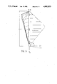
- FIG. 5 is a representation of an HVC color space for a particular CRT display device.
- FIG. 2 illustrates the sequence of steps for transforming any selected color, producible by a CRT color display, into a perceptually uniform color space that is based upon internationally accepted colorimetric standards.
- the perceptually uniform space will hereafter be referred to as the HVC space having coordinates H, V and C, the numerical values of which are described more fully below
- the display-based HVC space of the present invention can be implemented in any of a variety of graphics display systems such as the 4335 Color Graphics Workstation and the 4235 Graphics Terminal available from Tektronix, Inc., Beaverton, OR.
- a graphics display system is shown in the block diagram of FIG. 4.
- the graphics display system 10 includes a workstation 12 comprising input device 14, and a programmable processor 16 with associated memory 18.
- a video monitor or display terminal 20 is associated with the workstation.
- a preliminary step in carrying out the transformation process is to determine the colorimetric parameters of the display device.
- data corresponding to the CRT phosphor characteristics are compiled.
- the data represent a tabulation of the luminous intensity levels of the red, green and blue phosphors that correspond to each DAC value.
- DAC values are often defined in one unit increments ranging from 0-255, each DAC value being a numerical representation of the particular electron gun control level for exerting a phosphor to a corresponding level of luminance intensity.
- the DAC-value/intensity table for the red phosphor describes the intensity level profile for each red electron gun control level.
- the DAC-value/intensity data may be that specified by the CRT manufacturer; however, for applications requiring precise color control it is preferred that the DAC-value/intensity data be measured and periodically updated via suitable spectroradiometric means.
- the DAC-value/intensity tables are normalized to 1 and stored in the memory 18 of the graphics workstation 12.
- the CIE XYZ tristimulus values for each primary phosphor are obtained for a reference white color that is produced by the CRT.
- this tristimulus data is normalized so that the Y tristimulus value of the reference white will equal 1.
- the Y tristimulus value indicates the luminance of the color. Establishing the Y value at 1 will yield a corresponding scaling of the CIELUV metric lightness function L* at a maximum value of 100, which corresponds to the reference white of the display device.
- the tristimulus data is arranged in a RGB-to-XYZ matrix, denoted [A].
- the RGB-to-XYZ matrix elements represent the relative intensity contributions of the red, green and blue phosphors (columns) to the X, Y and Z values (rows) of the reference white.
- the RGB-to-XYZ matrix is next inverted to form an XYZ-to-RGB matrix, denoted [A -1 ], the significance of which is described more fully below.
- the HVC space is next initialized. That is, the constants and functions for defining the H, V and C coordinates of the HVC space are established for the particular CRT. Specifically, with reference to FIG. 5, the vertical axis, V, of the HVC space is defined as corresponding to the CIELUV metric lightness function L* or
- V coordinate is determined through use of equations (3) and (4), substituting V for L*.
- the H coordinate of the HVC space generally corresponds to the CIELUV hue angle and is assigned a range of integer values from 0 to 359 corresponding to one degree angular increments in the CIELUV u*v* plane.
- the vertex of the hue angle is aligned with the V axis
- the H coordinate is the integer value of the hue angle and is calculated as:
- H 0 is selected to establish the 0 value or origin of H at the color most commonly associated with the term "red".
- Color-order systems such as the well-known Munsell book of color, employ a collection of physical samples to identify various hues. Color-order systems should not be confused with the CIE color specification system. It is contemplated that the origin of the H coordinate may be established at colors other than red.
- the chroma coordinate C correlates to the gamut of colors that can be produced by the CRT, and is scaled to correspond to the value or V coordinate of the space.
- the CIELUV chroma calculation C* uv is modified by multiplying that chroma by a chroma factor C f , which is a function of the maximum obtainable chroma for a given CRT phosphor set.
- the C coordinate defined above provides a more perceptually uniform CRT-based color space than heretofore available and offers greatly enhanced predictability in color selection.
- the C coordinate is numerically scaled from 0 to 100, with 100 equated to the maximum chroma or C level providable by the CRT.
- the scaling is achieved by defining the chroma factor C f as:
- Multiplying the CIELUV chroma C* uv for a selected color by the chroma factor C f and by the V coordinate of the HVC space enhances the perceptual uniformity of the HVC space so that at any hue H, a change of n units in the C coordinate will produce a perceived color difference substantially equal to the perceived color difference that occurs if the change of n units is made in the V coordinate. Likewise, for any hue H, a change of n units in the V coordinate will produce a perceived color difference substantially equal to the perceived color difference that occurs if the change of n units is made in the C coordinate.
- the u* and v* coordinates of the red, green and blue phosphor vertices are computed.
- a phosphor vertex is the point in the color space corresponding to the full intensity of one phosphor with the intensities of the remaining phosphors being zero.
- the red phosphor vertex has the greatest C* uv level. The following calculation of the red phosphor vertex is provided to illustrate how all phosphor vertices are calculated.
- red-rgb matrix The calculation of the red vertex involves creation of a single column, three-row, red-rgb matrix, denoted [r].
- the red-rgb matrix elements represent the full intensity DAC value (normalized to 1) for the red phosphor, and 0 DAC values for the green and blue phosphors.
- Multiplication of the red-rgb matrix by the RGB-to-XYZ matrix [A] yields a red-XYZ matrix [R], the elements of which are the tristimulus values X r , Y r , Z r resulting from the full intensity red phosphor
- equation form ##EQU2##
- the CIE uniform chromaticity coordinates u', v' are next calculated for each vertex using equations (1) and (2).
- the u' n and v' n pair for the reference white is then calculated based on the previously-determined XYZ values of the reference white.
- the lightness function L* is calculated for each vertex.
- the lightness L* of the red vertex is determined by multiplying the RGB-to-XYZ matrix by the Y r row of the red-XYZ matrix to yield the Y vr tristimulus value corresponding to the red vertex or:
- the CIELUV chroma is then calculated according to equation (8).
- the maximum CIELUV chroma C* uv of all vertices is then selected and used in equation (13) to determine the chroma factor C f .
- a color is selected and designated in terms of the red, green and blue phosphor intensity combination that would yield the desired color.
- the DAC values of the video RGB system are typically used for such a designation.
- the DAC values are provided to the workstation processor 14 by any of a variety of input devices such as the depicted keyboard 16.
- the DAC values of the selected color form a 3-element rgb intensity vector. Each element of the vector denotes to the relative intensity contribution of each phosphor in creating the selected color.
- the rgb intensity vector is next multiplied by the above-described RGB-to-XYZ matrix [A] to yield the CIE tristimulus values X s , Y s , Z s for the selected color.
- the X s , Y s , Z s values are then converted into the HVC coordinates as described above with reference to equations (10), (11) and (12).
- the coordinates of the HVC space are then displayed on a display terminal 20, or otherwise made available for reference by the user.
- the corresponding CIE colorimetric parameters x, y and Y are also provided to the user to permit specification of the selected color in accordance with those internationally accepted standards.
- the H, V and C coordinates of the selected color are entered into the processor 16 of the graphics workstation 12 by a suitable input device such as the depicted keyboard 14.
- the u' axis component and v' axis component of the distance, D are then calculated using the hue angle, which, as seen in equations (7) and (11), is the sum of the selected coordinate H and H 0 . Accordingly, the u' s v' s coordinates of the selected point are calculated as follows:
- the u' s , v' s coordinates of the selected point are then employed to determine the tristimulus values of the selected point. Specifically, the values x and y are calculated using equations (1) and (2) and the calculated values of u' s and v' s .
- the selected X s Y s Z s tristimulus values are next multiplied by the XYZ-to-RGB matrix [A -1 ] to obtain the corresponding rgb intensity vector.
- the rgb intensity vector is converted to DAC values by use of the stored DAC-value/intensity tables.
- the DAC values corresponding to the selected color are applied to conventional digital-to-analog converters, corrected for gamma, and fed to the electron guns for displaying the selected color on the CRT display.
- the HVC space can be implemented with any color display device (for example, color CRT monitors, printers, copiers and the like) having any number of primaries for producing a color.
- a fourth primary such as yellow
- the calculations described above are readily adaptable to incorporate any number of primaries.
Abstract
Description
u'=4x/(-2x+12y+3)=4X/(X+15Y+3Z) (1)
v'=9y/(-2x+12y+3)=9Y/(X+15Y+3Z) (2)
u*=13 L* (u'-u'.sub.n) (5)
v*=13 L* (v'-v'.sub.n) (6)
h*=arctan (v*/u*) (7)
C*.sub.uv =(u*.sup.2 +v*.sup.2).sup.1/2 ( 8)
ΔE.sub.uv =[(ΔL*).sup.2 +(Δv*).sup.2 +(Δu*).sup.2 ].sup.1/2 ( 9)
V=L* (10)
H=(arctan(v*/u*)+K)H.sub.0 (11)
K=0° for u*>0 and v*>0;
K=90° for u*<0 and v*>0;
K=180° for u*<0 and v*<0;
K=270° for u*>0 and v*<0;
C=C*.sub.uv (C.sub.f)/13 (12)
C.sub.f =(100/maximum chroma C*.sub.uv for CRT)13 (13)
Y.sub.vr =[A]Y.sub.r
u'.sub.s =u'.sub.n +D (cos (H+H.sub.0)) (17)
v'.sub.s =v'.sub.n +D (sin (H+H.sub.0)) (18)
z=1.0-x-y (19)
X.sub.s =x (Y.sub.s /y) and (20)
Z.sub.s =z (Y.sub.s /y) (21)
Claims (24)
H=arctan (v*/u*)+K-H.sub.0,
V=L*
C=C*.sub.uv (V)/13
H=arctan (v*/u*)+K-H.sub.0,
V=L*
C=C*.sub.uv (V)(C.sub.f),
H=arctan (v*/u*)+K-H.sub.0,
C=(u.sup.2 *+v*.sup.2).sup.1/2 (V)/(13)
H=arctan (v*/u*)+K-H.sub.0,
V=L*
C=(u*.sup.2 +v*.sup.2).sup.1/2 (V)/(13)
H=arctan (v*/u*)+K-H.sub.0,
V=L*
C=(u*.sup.2 +v*.sup.2).sup.1/2 (C.sub.f)/13
H=arctan (v*/u*)+K-H.sub.0,
V=L*
C=(u.sup.2 *+v*.sup.2).sup.1/2( V)/(13)
Priority Applications (1)
| Application Number | Priority Date | Filing Date | Title |
|---|---|---|---|
| US07/325,428 US4985853A (en) | 1987-10-26 | 1989-03-20 | Display-based color system |
Applications Claiming Priority (2)
| Application Number | Priority Date | Filing Date | Title |
|---|---|---|---|
| US07/113,029 US4843573A (en) | 1987-10-26 | 1987-10-26 | Display-based color system |
| US07/325,428 US4985853A (en) | 1987-10-26 | 1989-03-20 | Display-based color system |
Related Parent Applications (1)
| Application Number | Title | Priority Date | Filing Date |
|---|---|---|---|
| US07/113,029 Continuation US4843573A (en) | 1987-10-26 | 1987-10-26 | Display-based color system |
Publications (1)
| Publication Number | Publication Date |
|---|---|
| US4985853A true US4985853A (en) | 1991-01-15 |
Family
ID=26810637
Family Applications (1)
| Application Number | Title | Priority Date | Filing Date |
|---|---|---|---|
| US07/325,428 Expired - Lifetime US4985853A (en) | 1987-10-26 | 1989-03-20 | Display-based color system |
Country Status (1)
| Country | Link |
|---|---|
| US (1) | US4985853A (en) |
Cited By (49)
| Publication number | Priority date | Publication date | Assignee | Title |
|---|---|---|---|---|
| US5309257A (en) * | 1991-12-31 | 1994-05-03 | Eastman Kodak Company | Method and apparatus for providing color matching between color output devices |
| US5319473A (en) * | 1991-11-27 | 1994-06-07 | Xerox Corporation | Methods and apparatus for performing real time color gamut compressions |
| US5351079A (en) * | 1991-11-21 | 1994-09-27 | Shiro Usui | Color balance adjusting apparatus using a decorrelating neural network |
| US5416890A (en) * | 1991-12-11 | 1995-05-16 | Xerox Corporation | Graphical user interface for controlling color gamut clipping |
| US5418895A (en) * | 1992-11-25 | 1995-05-23 | Eastman Kodak Company | Method for displaying a high quality digital color image on a limited color display |
| USH1506H (en) * | 1991-12-11 | 1995-12-05 | Xerox Corporation | Graphical user interface for editing a palette of colors |
| US5502458A (en) * | 1992-11-10 | 1996-03-26 | International Business Machines Corporation | Method and apparatus for creating and displaying faithfull color images on a computer display |
| US5543820A (en) * | 1992-08-14 | 1996-08-06 | International Business Machines Corporation | Method and apparatus for linear color processing |
| US5561459A (en) * | 1994-09-30 | 1996-10-01 | Apple Computer, Inc. | Automatic profile generation for a self-calibrating color display |
| US5710872A (en) * | 1995-03-23 | 1998-01-20 | Nikon Corporation | Color image recording device, system, and method |
| US5754184A (en) * | 1993-01-06 | 1998-05-19 | Eastman Kodak Company | Digital color system and method which provides a visual match across different input and output viewing conditions |
| US5809213A (en) * | 1996-02-23 | 1998-09-15 | Seiko Epson Corporation | Automatic color calibration of a color reproduction system |
| US5909291A (en) * | 1992-03-19 | 1999-06-01 | Apple Computer, Inc. | Color matching apparatus and method |
| US5963201A (en) * | 1992-05-11 | 1999-10-05 | Apple Computer, Inc. | Color processing system |
| US6005971A (en) * | 1996-10-18 | 1999-12-21 | International Business Machines Corporation | Method, system and program products for displaying multiple types of data in single images |
| US6081253A (en) * | 1998-02-10 | 2000-06-27 | Bronson Color Company, Inc. | Method for generating numerous harmonious color palettes from two colors |
| US6081276A (en) * | 1996-11-14 | 2000-06-27 | International Business Machines Corporation | Method and apparatus for creating a color name dictionary and for querying an image by color name |
| US6297826B1 (en) * | 1998-01-20 | 2001-10-02 | Fujitsu Limited | Method of converting color data |
| US6362849B1 (en) * | 1996-05-23 | 2002-03-26 | L'oreal | Color measuring method and device |
| US6366291B1 (en) * | 1997-07-17 | 2002-04-02 | Dainippon Screen Mfg. Co., Ltd. | Method of color conversion, apparatus for the same, and computer program product for realizing the method |
| US20020149546A1 (en) * | 2000-12-18 | 2002-10-17 | Moshe Ben-Chorin | Spectrally matched print proofer |
| US6611274B1 (en) | 1999-10-12 | 2003-08-26 | Microsoft Corporation | System method, and computer program product for compositing true colors and intensity-maped colors into a frame buffer |
| US20040164101A1 (en) * | 2003-02-20 | 2004-08-26 | Valois Sas | Fluid dispenser |
| US20040174389A1 (en) * | 2001-06-11 | 2004-09-09 | Ilan Ben-David | Device, system and method for color display |
| US20040184005A1 (en) * | 2001-07-12 | 2004-09-23 | Shmuel Roth | Sequential projection color display using multiple imaging panels |
| US20040201598A1 (en) * | 2001-07-23 | 2004-10-14 | Dan Eliav | Display for simulation of printed material |
| US20040233213A1 (en) * | 1999-05-31 | 2004-11-25 | Kenro Ohsawa | Color image display system |
| US20040246389A1 (en) * | 2002-07-24 | 2004-12-09 | Shmuel Roth | High brightness wide gamut display |
| US20050031199A1 (en) * | 2001-06-07 | 2005-02-10 | Moshe Ben-Chorin | System and method of data conversion for wide gamut displays |
| US6870523B1 (en) | 2000-06-07 | 2005-03-22 | Genoa Color Technologies | Device, system and method for electronic true color display |
| US20050122294A1 (en) * | 2002-04-11 | 2005-06-09 | Ilan Ben-David | Color display devices and methods with enhanced attributes |
| US20050134785A1 (en) * | 2003-12-15 | 2005-06-23 | Shmuel Roth | Multi-primary liquid crystal display |
| US20050190141A1 (en) * | 2002-01-07 | 2005-09-01 | Shmuel Roth | Device and method for projection device based soft proofing |
| US20050249402A1 (en) * | 2004-05-05 | 2005-11-10 | Canon Kabushiki Kaisha | Characterization of display devices by averaging chromaticity values |
| US20050259109A1 (en) * | 2004-05-19 | 2005-11-24 | Microsoft Corporation | System and method for a gamut mapping platform having plug-in transform functions |
| US20060069794A1 (en) * | 2003-01-03 | 2006-03-30 | Thomson Licensing Inc. | System for maintaining white uniformity in a displayed video image by predicting and compensating for display register changes |
| US20060226956A1 (en) * | 2005-04-07 | 2006-10-12 | Dialight Corporation | LED assembly with a communication protocol for LED light engines |
| US20060285217A1 (en) * | 2003-08-04 | 2006-12-21 | Genoa Color Technologies Ltd. | Multi-primary color display |
| US20070001994A1 (en) * | 2001-06-11 | 2007-01-04 | Shmuel Roth | Multi-primary display with spectrally adapted back-illumination |
| US20070150813A1 (en) * | 2002-02-26 | 2007-06-28 | Uni-Pixel Displays, Inc. | Extending the Gamut Color Generation in an Optical Flat Panel Display |
| US20080030660A1 (en) * | 2003-12-15 | 2008-02-07 | Shmuel Roth | Multi-color liquid crystal display |
| US20080111827A1 (en) * | 2001-01-29 | 2008-05-15 | Canon Kabushiki Kaisha | Color-information processing method, and program |
| US20080225055A1 (en) * | 2007-03-16 | 2008-09-18 | Innocom Technology (Shenzhen) Co., Ltd. | Method for obtaining primary color values of display device and method for establishing color correction tables of same |
| US20080244412A1 (en) * | 2007-03-30 | 2008-10-02 | Microsoft Corporation | Color management user interface |
| US20090135129A1 (en) * | 2001-06-11 | 2009-05-28 | Shmuel Roth | Method, device and system for multi-color sequential lcd panel |
| US20090179826A1 (en) * | 2005-11-28 | 2009-07-16 | Doron Malka | Sub-pixel rendering of a multiprimary image |
| US8228275B2 (en) | 2003-01-28 | 2012-07-24 | Genoa Color Technologies Ltd. | Optimal subpixel arrangement for displays with more than three primary colors |
| CN110705587A (en) * | 2019-08-28 | 2020-01-17 | 长春希达电子技术有限公司 | Automatic classification method for surface colors of LED display screen |
| US11037522B2 (en) * | 2014-12-24 | 2021-06-15 | Stmicroelectronics S.R.L. | Method for radiometric display, corresponding system, apparatus and computer program product |
Citations (8)
| Publication number | Priority date | Publication date | Assignee | Title |
|---|---|---|---|---|
| US4409614A (en) * | 1978-10-10 | 1983-10-11 | Helmut Eichler | Method for the reproduction of originals which, with respect to their color content, are scanned according to a tristimulus method |
| US4418359A (en) * | 1980-06-06 | 1983-11-29 | International Telephone And Telegraph Corporation | Omnispectravision |
| US4561016A (en) * | 1982-06-04 | 1985-12-24 | Dr. -Ing. Rudolf Hell Gmbh | Method and apparatus for recording color pictures for multicolor printing |
| US4628344A (en) * | 1982-09-14 | 1986-12-09 | New York Institute Of Technoloy | Method and apparatus for encoding and decoding video |
| US4656505A (en) * | 1983-12-30 | 1987-04-07 | Dainippon Screen Mfg. Co., Ltd. | Method for color correction for multi-color printing plate pictures |
| US4670780A (en) * | 1985-05-28 | 1987-06-02 | Tektronix, Inc. | Method of matching hardcopy colors to video display colors in which unreachable video display colors are converted into reachable hardcopy colors in a mixture-single-white (MSW) color space |
| US4670793A (en) * | 1984-02-10 | 1987-06-02 | Dainippon Screen Mfg. Co., Ltd. | Sharpness emphasis signal processing |
| US4703229A (en) * | 1985-10-10 | 1987-10-27 | United Technologies Corporation | Optical display from XeF excimer fluorescence |
-
1989
- 1989-03-20 US US07/325,428 patent/US4985853A/en not_active Expired - Lifetime
Patent Citations (8)
| Publication number | Priority date | Publication date | Assignee | Title |
|---|---|---|---|---|
| US4409614A (en) * | 1978-10-10 | 1983-10-11 | Helmut Eichler | Method for the reproduction of originals which, with respect to their color content, are scanned according to a tristimulus method |
| US4418359A (en) * | 1980-06-06 | 1983-11-29 | International Telephone And Telegraph Corporation | Omnispectravision |
| US4561016A (en) * | 1982-06-04 | 1985-12-24 | Dr. -Ing. Rudolf Hell Gmbh | Method and apparatus for recording color pictures for multicolor printing |
| US4628344A (en) * | 1982-09-14 | 1986-12-09 | New York Institute Of Technoloy | Method and apparatus for encoding and decoding video |
| US4656505A (en) * | 1983-12-30 | 1987-04-07 | Dainippon Screen Mfg. Co., Ltd. | Method for color correction for multi-color printing plate pictures |
| US4670793A (en) * | 1984-02-10 | 1987-06-02 | Dainippon Screen Mfg. Co., Ltd. | Sharpness emphasis signal processing |
| US4670780A (en) * | 1985-05-28 | 1987-06-02 | Tektronix, Inc. | Method of matching hardcopy colors to video display colors in which unreachable video display colors are converted into reachable hardcopy colors in a mixture-single-white (MSW) color space |
| US4703229A (en) * | 1985-10-10 | 1987-10-27 | United Technologies Corporation | Optical display from XeF excimer fluorescence |
Cited By (98)
| Publication number | Priority date | Publication date | Assignee | Title |
|---|---|---|---|---|
| US5351079A (en) * | 1991-11-21 | 1994-09-27 | Shiro Usui | Color balance adjusting apparatus using a decorrelating neural network |
| US5319473A (en) * | 1991-11-27 | 1994-06-07 | Xerox Corporation | Methods and apparatus for performing real time color gamut compressions |
| US5416890A (en) * | 1991-12-11 | 1995-05-16 | Xerox Corporation | Graphical user interface for controlling color gamut clipping |
| USH1506H (en) * | 1991-12-11 | 1995-12-05 | Xerox Corporation | Graphical user interface for editing a palette of colors |
| US5309257A (en) * | 1991-12-31 | 1994-05-03 | Eastman Kodak Company | Method and apparatus for providing color matching between color output devices |
| US5909291A (en) * | 1992-03-19 | 1999-06-01 | Apple Computer, Inc. | Color matching apparatus and method |
| US5963201A (en) * | 1992-05-11 | 1999-10-05 | Apple Computer, Inc. | Color processing system |
| US5543820A (en) * | 1992-08-14 | 1996-08-06 | International Business Machines Corporation | Method and apparatus for linear color processing |
| US5502458A (en) * | 1992-11-10 | 1996-03-26 | International Business Machines Corporation | Method and apparatus for creating and displaying faithfull color images on a computer display |
| US5614925A (en) * | 1992-11-10 | 1997-03-25 | International Business Machines Corporation | Method and apparatus for creating and displaying faithful color images on a computer display |
| US5418895A (en) * | 1992-11-25 | 1995-05-23 | Eastman Kodak Company | Method for displaying a high quality digital color image on a limited color display |
| US5754184A (en) * | 1993-01-06 | 1998-05-19 | Eastman Kodak Company | Digital color system and method which provides a visual match across different input and output viewing conditions |
| US5561459A (en) * | 1994-09-30 | 1996-10-01 | Apple Computer, Inc. | Automatic profile generation for a self-calibrating color display |
| US5710872A (en) * | 1995-03-23 | 1998-01-20 | Nikon Corporation | Color image recording device, system, and method |
| US5809213A (en) * | 1996-02-23 | 1998-09-15 | Seiko Epson Corporation | Automatic color calibration of a color reproduction system |
| US6362849B1 (en) * | 1996-05-23 | 2002-03-26 | L'oreal | Color measuring method and device |
| US6005971A (en) * | 1996-10-18 | 1999-12-21 | International Business Machines Corporation | Method, system and program products for displaying multiple types of data in single images |
| US6081276A (en) * | 1996-11-14 | 2000-06-27 | International Business Machines Corporation | Method and apparatus for creating a color name dictionary and for querying an image by color name |
| US6366291B1 (en) * | 1997-07-17 | 2002-04-02 | Dainippon Screen Mfg. Co., Ltd. | Method of color conversion, apparatus for the same, and computer program product for realizing the method |
| US6297826B1 (en) * | 1998-01-20 | 2001-10-02 | Fujitsu Limited | Method of converting color data |
| US6081253A (en) * | 1998-02-10 | 2000-06-27 | Bronson Color Company, Inc. | Method for generating numerous harmonious color palettes from two colors |
| US20040233213A1 (en) * | 1999-05-31 | 2004-11-25 | Kenro Ohsawa | Color image display system |
| US6611274B1 (en) | 1999-10-12 | 2003-08-26 | Microsoft Corporation | System method, and computer program product for compositing true colors and intensity-maped colors into a frame buffer |
| US6870523B1 (en) | 2000-06-07 | 2005-03-22 | Genoa Color Technologies | Device, system and method for electronic true color display |
| US7113152B2 (en) | 2000-06-07 | 2006-09-26 | Genoa Color Technologies Ltd. | Device, system and method for electronic true color display |
| US8310498B2 (en) | 2000-12-18 | 2012-11-13 | Samsung Display Co., Ltd. | Spectrally matched print proofer |
| US20020149546A1 (en) * | 2000-12-18 | 2002-10-17 | Moshe Ben-Chorin | Spectrally matched print proofer |
| US20080218784A1 (en) * | 2000-12-18 | 2008-09-11 | Moshe Ben-Chorin | Spectrally matched print proofer |
| US7352488B2 (en) | 2000-12-18 | 2008-04-01 | Genoa Color Technologies Ltd | Spectrally matched print proofer |
| US8654118B2 (en) * | 2001-01-29 | 2014-02-18 | Canon Kabushiki Kaisha | Color-information processing method, and program |
| US20080111827A1 (en) * | 2001-01-29 | 2008-05-15 | Canon Kabushiki Kaisha | Color-information processing method, and program |
| US8599226B2 (en) | 2001-06-07 | 2013-12-03 | Genoa Color Technologies Ltd. | Device and method of data conversion for wide gamut displays |
| US8115787B2 (en) | 2001-06-07 | 2012-02-14 | Genoa Color Technologies Ltd. | Device, system and method of data conversion for wide gamut displays |
| US20050031199A1 (en) * | 2001-06-07 | 2005-02-10 | Moshe Ben-Chorin | System and method of data conversion for wide gamut displays |
| US7436996B2 (en) | 2001-06-07 | 2008-10-14 | Genoa Color Technologies Ltd | Device, system and method of data conversion for wide gamut displays |
| US7995019B2 (en) | 2001-06-11 | 2011-08-09 | Genoa Color Technologies Ltd. | Device, system and method for color display |
| US20090135129A1 (en) * | 2001-06-11 | 2009-05-28 | Shmuel Roth | Method, device and system for multi-color sequential lcd panel |
| US9851599B2 (en) | 2001-06-11 | 2017-12-26 | Samsung Display Co., Ltd. | Color display device comprising at least six different primary colors |
| US9430974B2 (en) | 2001-06-11 | 2016-08-30 | Samsung Display Co., Ltd. | Multi-primary display with spectrally adapted back-illumination |
| US9196203B2 (en) | 2001-06-11 | 2015-11-24 | Samsung Display Co., Ltd. | Device and system for a multi-color sequential LCD panel wherein the number of colors in a sequence of display colors is greater than the number of LED colors |
| US8885120B2 (en) | 2001-06-11 | 2014-11-11 | Genoa Color Technologies Ltd. | Liquid crystal display device using a color-sequential method wherein the number of different colored LEDs is less than the number of primary colors used in the display |
| US20040174389A1 (en) * | 2001-06-11 | 2004-09-09 | Ilan Ben-David | Device, system and method for color display |
| US8558857B2 (en) | 2001-06-11 | 2013-10-15 | Genoa Color Technologies Ltd. | Device, system and method for color display |
| US8289266B2 (en) | 2001-06-11 | 2012-10-16 | Genoa Color Technologies Ltd. | Method, device and system for multi-color sequential LCD panel |
| US20070001994A1 (en) * | 2001-06-11 | 2007-01-04 | Shmuel Roth | Multi-primary display with spectrally adapted back-illumination |
| US8248440B2 (en) | 2001-06-11 | 2012-08-21 | Genoa Color Technologies Ltd. | Device, system and method for color display |
| US7268757B2 (en) | 2001-06-11 | 2007-09-11 | Genoa Color Technologies Ltd | Device, system and method for color display |
| US20080024410A1 (en) * | 2001-06-11 | 2008-01-31 | Ilan Ben-David | Device, system and method for color display |
| US20080030447A1 (en) * | 2001-06-11 | 2008-02-07 | Ilan Ben-David | Device, system and method for color display |
| US7990403B2 (en) | 2001-06-11 | 2011-08-02 | Genoa Color Technologies Ltd. | Device, system and method for color display |
| US20100214311A1 (en) * | 2001-06-11 | 2010-08-26 | Shmuel Roth | Multi-primary display with spectrally adapted back-illumination |
| US7714824B2 (en) | 2001-06-11 | 2010-05-11 | Genoa Color Technologies Ltd. | Multi-primary display with spectrally adapted back-illumination |
| US20080192178A1 (en) * | 2001-06-11 | 2008-08-14 | Ilan Ben-David | Device, system and method for color display |
| US6962414B2 (en) | 2001-07-12 | 2005-11-08 | Genoa Color Technologies Ltd. | Sequential projection color display using multiple imaging panels |
| US7077524B2 (en) | 2001-07-12 | 2006-07-18 | Genoa Color Technologies Ltd | Sequential projection color display using multiple imaging panels |
| US20050275806A1 (en) * | 2001-07-12 | 2005-12-15 | Shmuel Roth | Sequential projection color display using multiple imaging panels |
| US20040184005A1 (en) * | 2001-07-12 | 2004-09-23 | Shmuel Roth | Sequential projection color display using multiple imaging panels |
| US20040201598A1 (en) * | 2001-07-23 | 2004-10-14 | Dan Eliav | Display for simulation of printed material |
| US7486413B2 (en) | 2001-07-23 | 2009-02-03 | Genoa Color Technologies Ltd. | System and method for displaying an image |
| US7999823B2 (en) | 2002-01-07 | 2011-08-16 | Samsung Electronics Co., Ltd. | Device and method for projection device based soft proofing |
| US20050190141A1 (en) * | 2002-01-07 | 2005-09-01 | Shmuel Roth | Device and method for projection device based soft proofing |
| US20070150813A1 (en) * | 2002-02-26 | 2007-06-28 | Uni-Pixel Displays, Inc. | Extending the Gamut Color Generation in an Optical Flat Panel Display |
| US7522354B2 (en) | 2002-02-26 | 2009-04-21 | Uni-Pixel Displays, Inc. | Enhancing a field sequential color palette in an optical display |
| US8077376B2 (en) | 2002-02-26 | 2011-12-13 | Rambus Inc. | Visible plus non-visible field sequential color |
| US8014057B2 (en) | 2002-02-26 | 2011-09-06 | Rambus Inc. | Extending the gamut color generation in a display |
| US20090262129A1 (en) * | 2002-02-26 | 2009-10-22 | Uni-Pixel Displays, Inc. | Extending the gamut color generation in a display |
| US20050122294A1 (en) * | 2002-04-11 | 2005-06-09 | Ilan Ben-David | Color display devices and methods with enhanced attributes |
| US9953590B2 (en) | 2002-04-11 | 2018-04-24 | Samsung Display Co., Ltd. | Color display devices and methods with enhanced attributes |
| US7471822B2 (en) | 2002-07-24 | 2008-12-30 | Genoa Color Technologies Ltd | Method and apparatus for high brightness wide color gamut display |
| US20100134515A1 (en) * | 2002-07-24 | 2010-06-03 | Shmuel Roth | High brightness wide gamut display |
| US7916939B2 (en) | 2002-07-24 | 2011-03-29 | Samsung Electronics Co., Ltd. | High brightness wide gamut display |
| US20040246389A1 (en) * | 2002-07-24 | 2004-12-09 | Shmuel Roth | High brightness wide gamut display |
| US20060069794A1 (en) * | 2003-01-03 | 2006-03-30 | Thomson Licensing Inc. | System for maintaining white uniformity in a displayed video image by predicting and compensating for display register changes |
| US8228275B2 (en) | 2003-01-28 | 2012-07-24 | Genoa Color Technologies Ltd. | Optimal subpixel arrangement for displays with more than three primary colors |
| US20040164101A1 (en) * | 2003-02-20 | 2004-08-26 | Valois Sas | Fluid dispenser |
| US20060285217A1 (en) * | 2003-08-04 | 2006-12-21 | Genoa Color Technologies Ltd. | Multi-primary color display |
| US7417799B2 (en) | 2003-08-04 | 2008-08-26 | Genoa Color Technologies Ltd. | Multi-primary color display |
| US20090128755A1 (en) * | 2003-12-15 | 2009-05-21 | Shmuel Roth | Multi-color liquid crystal display |
| US20080030660A1 (en) * | 2003-12-15 | 2008-02-07 | Shmuel Roth | Multi-color liquid crystal display |
| US8179502B2 (en) | 2003-12-15 | 2012-05-15 | Genoa Color Technologies Ltd. | Multi-color liquid crystal display |
| US20110037929A1 (en) * | 2003-12-15 | 2011-02-17 | Shmuel Roth | Multi-color liquid crystal display |
| US20050134785A1 (en) * | 2003-12-15 | 2005-06-23 | Shmuel Roth | Multi-primary liquid crystal display |
| US8934072B2 (en) | 2003-12-15 | 2015-01-13 | Genoa Color Technologies Ltd. | Multi-color liquid crystal display |
| US8451405B2 (en) | 2003-12-15 | 2013-05-28 | Genoa Color Technologies Ltd. | Multi-color liquid crystal display |
| US7495722B2 (en) | 2003-12-15 | 2009-02-24 | Genoa Color Technologies Ltd. | Multi-color liquid crystal display |
| US7483095B2 (en) | 2003-12-15 | 2009-01-27 | Genoa Color Technologies Ltd | Multi-primary liquid crystal display |
| US20050249402A1 (en) * | 2004-05-05 | 2005-11-10 | Canon Kabushiki Kaisha | Characterization of display devices by averaging chromaticity values |
| US7085414B2 (en) * | 2004-05-05 | 2006-08-01 | Canon Kabushiki Kaisha | Characterization of display devices by averaging chromaticity values |
| US20050259109A1 (en) * | 2004-05-19 | 2005-11-24 | Microsoft Corporation | System and method for a gamut mapping platform having plug-in transform functions |
| US20060226956A1 (en) * | 2005-04-07 | 2006-10-12 | Dialight Corporation | LED assembly with a communication protocol for LED light engines |
| US20090179826A1 (en) * | 2005-11-28 | 2009-07-16 | Doron Malka | Sub-pixel rendering of a multiprimary image |
| US8587621B2 (en) | 2005-11-28 | 2013-11-19 | Genoa Color Technologies Ltd. | Sub-pixel rendering of a multiprimary image |
| US20080225055A1 (en) * | 2007-03-16 | 2008-09-18 | Innocom Technology (Shenzhen) Co., Ltd. | Method for obtaining primary color values of display device and method for establishing color correction tables of same |
| US8040356B2 (en) | 2007-03-30 | 2011-10-18 | Microsoft Corporation | Color management user interface |
| US20080244412A1 (en) * | 2007-03-30 | 2008-10-02 | Microsoft Corporation | Color management user interface |
| US11037522B2 (en) * | 2014-12-24 | 2021-06-15 | Stmicroelectronics S.R.L. | Method for radiometric display, corresponding system, apparatus and computer program product |
| CN110705587A (en) * | 2019-08-28 | 2020-01-17 | 长春希达电子技术有限公司 | Automatic classification method for surface colors of LED display screen |
| CN110705587B (en) * | 2019-08-28 | 2023-04-18 | 长春希达电子技术有限公司 | Automatic classification method for surface colors of LED display screen |
Similar Documents
| Publication | Publication Date | Title |
|---|---|---|
| US4985853A (en) | Display-based color system | |
| US4843573A (en) | Display-based color system | |
| EP0313796B1 (en) | Computer display color control and selection system | |
| US5231504A (en) | Method for improved color reproduction using linear mixing calculations based on positional relationships between an original color and an achromatic region in a linear mixing space | |
| US5254978A (en) | Reference color selection system | |
| US7215343B2 (en) | Color correction using a device-dependent display profile | |
| US5311212A (en) | Functional color selection system | |
| US5243414A (en) | Color processing system | |
| Fairchild et al. | Meet iCAM: A next-generation color appearance model | |
| US7629983B2 (en) | Correction techniques for soft proofing | |
| KR100513759B1 (en) | Color signal processing device and method for multi-primary color display | |
| EP0546773A2 (en) | Graphical user interface for editing a palette of colours | |
| US20070154083A1 (en) | Editing of digital images, including (but not limited to) highlighting and shadowing of image areas | |
| US7495801B2 (en) | Editing (including hue editing) of digital color images | |
| Masaoka | Display gamut metrology using chromaticity diagram | |
| Fang et al. | 78‐2: A Matrix‐Based Method of Color Correction for Metamerism Failure between LCD and OLED | |
| JP3130589B2 (en) | Color arrangement support method and apparatus | |
| US7589866B2 (en) | Editing of digital images, including (but not limited to) color-to-monochromatic conversion and changing the color of a monochromatic image | |
| US7495800B2 (en) | Color coordinate systems including systems with a coordinate defined by a square root of a quadratic polynomial in tristimulus values and, possibly, by a sign of a function of one or more of tristimulus values | |
| Meyer | Reproducing and synthesizing colour in computer graphics | |
| Rhodes | Colour management for the textile industry | |
| Neri | Color CRT characterization presented solely in terms of the CIE system | |
| Laihanen | New approach to the manipulation of color display images | |
| Dubois | Subspaces and Decompositions of the Human Color Space | |
| Plaisted et al. | Color-Image. com |
Legal Events
| Date | Code | Title | Description |
|---|---|---|---|
| STCF | Information on status: patent grant |
Free format text: PATENTED CASE |
|
| FEPP | Fee payment procedure |
Free format text: PAYOR NUMBER ASSIGNED (ORIGINAL EVENT CODE: ASPN); ENTITY STATUS OF PATENT OWNER: LARGE ENTITY |
|
| FPAY | Fee payment |
Year of fee payment: 4 |
|
| CC | Certificate of correction | ||
| FPAY | Fee payment |
Year of fee payment: 8 |
|
| FEPP | Fee payment procedure |
Free format text: PAYER NUMBER DE-ASSIGNED (ORIGINAL EVENT CODE: RMPN); ENTITY STATUS OF PATENT OWNER: LARGE ENTITY Free format text: PAYOR NUMBER ASSIGNED (ORIGINAL EVENT CODE: ASPN); ENTITY STATUS OF PATENT OWNER: LARGE ENTITY |
|
| AS | Assignment |
Owner name: XEROX CORPORATION, CONNECTICUT Free format text: ASSIGNMENT OF ASSIGNORS INTEREST;ASSIGNOR:TEKTRONIX, INC.;REEL/FRAME:010609/0287 Effective date: 19991217 |
|
| FPAY | Fee payment |
Year of fee payment: 12 |
|
| AS | Assignment |
Owner name: BANK ONE, NA, AS ADMINISTRATIVE AGENT, ILLINOIS Free format text: SECURITY INTEREST;ASSIGNOR:XEROX CORPORATION;REEL/FRAME:013153/0001 Effective date: 20020621 |
|
| AS | Assignment |
Owner name: JPMORGAN CHASE BANK, AS COLLATERAL AGENT, TEXAS Free format text: SECURITY AGREEMENT;ASSIGNOR:XEROX CORPORATION;REEL/FRAME:015134/0476 Effective date: 20030625 Owner name: JPMORGAN CHASE BANK, AS COLLATERAL AGENT,TEXAS Free format text: SECURITY AGREEMENT;ASSIGNOR:XEROX CORPORATION;REEL/FRAME:015134/0476 Effective date: 20030625 |
|
| AS | Assignment |
Owner name: XEROX CORPORATION, CONNECTICUT Free format text: RELEASE BY SECURED PARTY;ASSIGNOR:JPMORGAN CHASE BANK, N.A. AS SUCCESSOR-IN-INTEREST ADMINISTRATIVE AGENT AND COLLATERAL AGENT TO JPMORGAN CHASE BANK;REEL/FRAME:066728/0193 Effective date: 20220822 |