US4977754A - Next-to-be-purchased cold beverage merchandiser - Google Patents
Next-to-be-purchased cold beverage merchandiser Download PDFInfo
- Publication number
- US4977754A US4977754A US07/517,345 US51734590A US4977754A US 4977754 A US4977754 A US 4977754A US 51734590 A US51734590 A US 51734590A US 4977754 A US4977754 A US 4977754A
- Authority
- US
- United States
- Prior art keywords
- compartment
- disposed
- wall
- housing
- duct
- Prior art date
- Legal status (The legal status is an assumption and is not a legal conclusion. Google has not performed a legal analysis and makes no representation as to the accuracy of the status listed.)
- Expired - Fee Related
Links
Images


Classifications
-
- A—HUMAN NECESSITIES
- A47—FURNITURE; DOMESTIC ARTICLES OR APPLIANCES; COFFEE MILLS; SPICE MILLS; SUCTION CLEANERS IN GENERAL
- A47F—SPECIAL FURNITURE, FITTINGS, OR ACCESSORIES FOR SHOPS, STOREHOUSES, BARS, RESTAURANTS OR THE LIKE; PAYING COUNTERS
- A47F3/00—Show cases or show cabinets
- A47F3/04—Show cases or show cabinets air-conditioned, refrigerated
- A47F3/0404—Cases or cabinets of the closed type
- A47F3/0408—Cases or cabinets of the closed type with forced air circulation
-
- F—MECHANICAL ENGINEERING; LIGHTING; HEATING; WEAPONS; BLASTING
- F25—REFRIGERATION OR COOLING; COMBINED HEATING AND REFRIGERATION SYSTEMS; HEAT PUMP SYSTEMS; MANUFACTURE OR STORAGE OF ICE; LIQUEFACTION SOLIDIFICATION OF GASES
- F25D—REFRIGERATORS; COLD ROOMS; ICE-BOXES; COOLING OR FREEZING APPARATUS NOT OTHERWISE PROVIDED FOR
- F25D21/00—Defrosting; Preventing frosting; Removing condensed or defrost water
- F25D21/04—Preventing the formation of frost or condensate
-
- F—MECHANICAL ENGINEERING; LIGHTING; HEATING; WEAPONS; BLASTING
- F25—REFRIGERATION OR COOLING; COMBINED HEATING AND REFRIGERATION SYSTEMS; HEAT PUMP SYSTEMS; MANUFACTURE OR STORAGE OF ICE; LIQUEFACTION SOLIDIFICATION OF GASES
- F25D—REFRIGERATORS; COLD ROOMS; ICE-BOXES; COOLING OR FREEZING APPARATUS NOT OTHERWISE PROVIDED FOR
- F25D2331/00—Details or arrangements of other cooling or freezing apparatus not provided for in other groups of this subclass
- F25D2331/80—Type of cooled receptacles
- F25D2331/803—Bottles
Definitions
- the present invention relates to cold beverage merchandisers and more particularly to a forced cold air circulation, continuously defogged, cold beverage merchandiser.
- Refrigerated cabinets for merchandising six-packs typically have horizontal shelves and an evaporator disposed in the upper rear portion of the cabinet.
- the flow of cold air typically is directed by a fan downwardly from the evaporator along the rear wall of the cabinet to the bottom of the cabinet, frontwardly along the bottom of the cabinet to the front glass panels of the cabinet, then upwardly along the front glass panels of the cabinet to the top of the cabinet, and rearwardly along the top of the cabinet to the evaporator.
- the width of the evaporator extended approximately the width of the cabinet, and the height of the evaporator extended in a direction parallel to the height of the cabinet.
- the depth of the evaporator was the smallest dimension of these evaporators and extended in a direction parallel to the depth of the cabinet.
- the height of the evaporator was the smallest dimension and extended in a direction parallel to the height (measured from top to bottom) of the cabinet.
- U.S. Pat. No. 3,462,966 to Reid et al discloses a way of removing condensation forming on the inner surface of a glass panel of a refrigerator door when the door is opened.
- This refrigerated cabinet has a pair of door panels. Each door has a tubular frame 32 around the perimeter of a glass panel 34. The door panels are hingedly mounted on the front edge portion 14 of the cabinet.
- a condenser coil assembly 54 is mounted within a non-refrigerated space below the refrigerated space and insulated therefrom.
- a condenser fan 56 is also mounted within the non-refrigerated space rearwardly of the condenser coil.
- an air scoop device 78 Centrally mounted within the non-refrigerated space at the forward end is an air scoop device 78 provided with a dimensionally enlarged inlet end aligned with the condenser coil assembly 54 and close thereto to converge forwardly from the inlet to an outlet end positioned just below the forward edge portion of the wall 28 which partitions the refrigerated space from the non-refrigerated space.
- the air flow is induced to pass between the coils of the condenser coil assembly for heat exchange purposes that results in the discharge of heated air through a front grill 16 which extends horizontally across the lower front portion of the cabinet and is removably mounted thereon.
- a deflecting portion 96 of the grill work behind front grill 16 cooperates with scoop device 78 and duct forming members 98 to laterally distribute the air flowing upwardly from an opening in the grill.
- the front grill discharges warm air vertically in an upward direction to form a warm air curtain in front of the access opening closed by the door panels.
- the access opening to the refrigerated space is formed in a plane with which the front edge portions of the cabinet walls are aligned.
- Magnetic strips within peripheral sealing elements or strips are mounted on the tubular frame of each door panel for contact with the forward edge portions of the side walls, the partition wall 28 separating the refrigerated cabinet from the non-refrigerated cabinet, and the top wall. The magnetic strips cooperate with the magnetic inserts to hold the door panels closed.
- the door panels are disposed externally of the cabinet rather than being recessed in the edge portions of the cabinet walls as in prior constructions. This prevents the door panels from being directly exposed to the cold zone of the refrigerated space.
- the door panels also extend downwardly beyond the refrigerated space and overlap the front edge portion of the wall 28 which separates the refrigerated space from the non-refrigerated space.
- the air rising from the front grill immediately contacts the tubular frames of the door panel assemblies.
- the upward air flow forms an air curtain or barrier between the atmosphere and the refrigerated space, this air curtain being more effective in defogging the door panels because of the panel mounting externally of the cabinet.
- the compressor fan is operated continuously, rather than only when the compressor is operating in its refrigeration cycle. This reduces the efficiency of the refrigeration equipment. Moreover, the location of the condenser and compressor fan near the floor results in the transfer of dust and dirt into the condenser when the compressor fan operates. Continuous operation of the compressor fan provides a continuous flow of dust and dirt into the condenser. Periodic removal of such extraneous matter from the condenser is required to maintain the efficiency of the condenser and compressor operation at acceptable levels.
- diagonally disposed side struts (unnumbered) are used to bear the load of the cabinet and transfer it to the base panel, which is supported by the cabinet legs that bear the entire weight of the cabinet.
- the attachment of the triangular struts to the base panel results in structural stresses that are borne by the 0.075 inch thickness (14 gauge) of the base panel.
- load bearing diagonally disposed struts mount upon and transfer the weight of the machine directly to the central shaft of the legs of the washing machine cabinet.
- Another principal object of the present invention is to provide a refrigerated beverage merchandiser that permits relatively easy and uncomplicated servicing of the refrigeration equipment.
- a still further principal object of the present invention is to provide a refrigerated beverage merchandiser that is efficiently constructed to minimize the gauge of the panels while not sacrificing load bearing capability.
- Yet another principal object of the present invention is to provide a beverage merchandiser that maximizes the storage capacity of the space in the refrigerated compartment.
- the refrigerated merchandiser of the present invention preferably includes a refrigerated compartment for holding items to be cooled.
- the compartment preferably is surrounded by heat insulation and defines a rear wall, a top wall, a pair of end walls, a front wall, and a bottom wall.
- the selective access means preferably includes a compartment access opening and at least one door having at least one transparent glass panel.
- Each compartment access opening permits patrons to gain access to the interior of the compartment for the purpose of removing refrigerated items stored in the compartment.
- Each compartment access opening preferably is defined at least in part near a free edge of the front wall of the compartment.
- each door has a triple pane glass panel.
- the doors of the selective access means can be sliding doors.
- the selective access means further includes at least two rotatable rollers attached to the top edge of each door, and at least two overhead tracks arranged side-by-side. Each track receives the rollers attached to each door and extends along the length of the access openings Each track preferably is disposed above the compartment access opening.
- a housing which is heat insulated from the refrigerated compartment.
- the housing preferably defines a top panel connected to two opposed side panels and combining to define a front opening.
- a cabinet for enclosing the compartment and the housing therewithin.
- the cabinet preferably includes a base.
- a condenser is mounted for selective disposition into and out of the housing.
- the condenser is disposed near the front opening of the housing.
- a compressor is mounted for selective disposition into and out of the housing.
- the compressor preferably is mounted farther from the front opening of the housing than the condenser.
- a condenser fan is provided for operating in conjunction with the operating cycle of the compressor.
- the condenser fan preferably is disposed between the compressor and the condenser.
- a condensate tray also can be disposed between the compressor and condenser fan.
- the defogging means preferably includes an elongated channel disposed below the selective access means along the front of the merchandiser and communicating with the housing to receive warmed air from the housing.
- the channel preferably has an exit slot defined by a front edge member having a free edge disposed parallel to the selective access means.
- the defogging means also preferably includes an auxiliary blower disposed in the housing to one side of the condenser and the compressor and having an inlet disposed to face toward the air space between the condenser and the compressor.
- the defogging means further preferably includes a conduit having one end communicating with the outlet of the auxiliary blower and an opposite communicating with the channel.
- the conduit preferably includes a flexible portion.
- the channel preferably is disposed in an elongated front grill that is disposed in front of the front opening of the housing. When the doors are closed to block access through the opening of the compartment, the channel preferably extends substantially the full length of the extent of the glass panels of the doors.
- an enclosure for housing a lighting display.
- This enclosure preferably is defined between the compartment and the cabinet and is disposed above the selective access means.
- This embodiment of the defogging means also includes a lamp fixture disposed in the enclosure for receiving a lamp which generates heat when in use.
- This embodiment of the defogging means also includes an elongated exit chute disposed in the enclosure at a location close to the selective access means.
- This embodiment of the defogging means further includes an auxiliary fan disposed so as to move air heated by a lamp in the light fixture through the exit chute of the enclosure when the fan is activated.
- the auxiliary fan preferably is disposed to generate a current of air moving in a direction going from one compartment end wall to the opposite compartment end wall.
- This embodiment of the defogging means also preferably includes a front exit lip member extending substantially the full length of the extent of the selective access means along the front of the merchandiser. This front exit lip member preferably is configured and disposed to direct air exiting the chute so as to attach the air flow to the exterior surface of the selective access means.
- an evaporator is provided and disposed inside the refrigerated compartment near the top wall of the compartment and closer to the rear wall than to the front wall.
- the evaporator produces cooled air in its vicinity.
- the evaporator preferably is shaped as a right angle parallelepiped having a width extending between the two end walls of the refrigerated compartment, a height disposed to extend in a direction normal to the top wall of the compartment and parallel to the rear wall of the compartment, and a depth disposed to extend in a direction normal to the rear wall of the compartment and parallel to the top wall of the compartment.
- the height of the evaporator is the smallest dimension
- the width is the largest dimension.
- means are provided for circulating the cooled air leaving the evaporator so that the path of cool air circulation begins by moving toward the selective access means before the cooled air moves toward any other portion of the compartment.
- the cooled air can be directed toward the product stored closest to the selective access means near the front opening of the compartment. This facilitates priority cooling of the next-to-be-purchased product located closest to the selective access means.
- the cooled air circulation means preferably includes a duct panel and a cold air blower.
- the duct panel preferably is disposed near the top of the compartment and defines a duct having an opened rear end facing away from the selective access means and toward the rear wall of the compartment.
- the evaporator preferably is disposed at the rear end of this duct.
- the duct panel also has a forward free edge that defines a duct exit and is configured to direct air exiting from the duct toward the selective access means.
- the cold air blower preferably is disposed relative to the duct for moving air cooled by the evaporator through the duct exit.
- the forward free edge that defines the duct exit preferably is disposed at the free end of a forward exit flap of the duct panel that is configured to direct air exiting from the duct toward the doors that provide selective patron access to the refrigerated compartment opening.
- the front compartment wall preferably extends from the top compartment wall and is configured to direct air flow toward the duct exit.
- means are provided for pivotally supporting the rear end of the duct panel.
- the pivotal supporting means preferably includes a cylindrical mounting post that extends from each compartment end wall.
- the pivotally supporting means further includes a hooked rear end disposed at the rear end of the duct panel for engaging the cylindrical mounting post.
- means are provided for detachably supporting the duct panel at a predetermined orientation relative to the selective compartment access means.
- the detachably supporting means preferably includes a twist lock or a knurled head fastener
- the detachably supporting means also includes a keyed flange extending from each of the end walls for engaging the twist lock or knurled head fastener.
- a fixture for a fluorescent lamp can be mounted to the underside of the duct panel in the vicinity of the forward exit flap to cast light on the product stored in the refrigerated compartment.
- At least four legs are provided for supporting the cabinet above the floor on which the merchandiser rests.
- Each leg has a central shaft extending vertically through the base of the housing.
- at least four load bearing braces are provided.
- Each brace has one end extending from beneath the top panel of the housing and an opposite end mounting at one of the central shafts of the legs.
- at least one hanger is provided for carrying the housing.
- four hangers are provided, and each hanger has one end carried by the end of each of the load bearing braces that extend from beneath the top panel of the housing.
- shelving for supporting beverage containers.
- Each shelf preferably extends from just in front of the rear wall of the compartment to just behind the access opening of the compartment.
- the shelves are mounted on front standards and rear standards.
- the standards are mounted to the compartment end walls with a key-hole and stud attachment mechanism.
- the rear standards are mounted higher above the compartment bottom wall than the front standards so that the end of each shelf nearest the rear compartment wall is disposed at a greater height from the bottom compartment wall than the end of the shelf nearest the compartment access opening.
- FIG. 1 illustrates an elevated perspective view from the front and side of a preferred embodiment of the refrigerated beverage cabinet constructed in accordance with the present invention
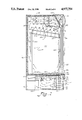
- FIG. 2 illustrates a cut-away side plan view taken along the line of sight 2--2 in the direction of the arrows in FIG. 1;
- FIG. 3 is side plan cut-away view of an alternative preferred embodiment of components of the present invention.
- FIG. 4 illustrates a partial cut-away plan view taken along the line of sight indicated by the direction in which arrows 4--4 point in FIG. 1;
- FIG. 5 illustrates a partially cut-away plan view taken along the line of sight indicated by the direction in which arrows 5--5 point in FIG. 1.
- FIG. 1 A preferred embodiment of the next-to-be-purchased cold beverage merchandiser of the present invention is shown in FIG. 1 and is represented generally by the numeral 10.
- a refrigerated compartment is provided for holding items to be cooled.
- the refrigerated compartment preferably is defined by a rear wall, a top wall, a pair of end walls, a front wall, and a bottom wall.
- a compartment is indicated generally by the numeral 12 and is defined by a rear wall 14, a top wall 16, a front wall 18, and a bottom wall 20.
- compartment 12 is further defined by opposing end walls 22, 24.
- Heat insulation 46 (shown by looping line) is provided around the outside of the walls forming compartment 12.
- the selective access means includes at least one compartment access opening defined between the bottom wall and the front wall of the compartment. As shown in FIGS. 2 and 3 for example, each compartment access opening preferably is defined at least in part near a free edge of front wall 18.
- the selective access means further preferably includes at least one door.
- the doors can be hinged to open outwardly from the merchandiser or can be mounted to slide from side-to-side across the compartment access opening. When the door is opened, it provides access to the compartment opening. When the door is closed, it denies access to the compartment opening. Thus, the door selectively limits access to the compartment access opening by selectively providing and denying access to the compartment access opening.
- a side-by-side pair of sliding doors are indicated generally by the designating numerals 26 and 28.
- Each door 26, 28 preferably includes a triple pane, glass panel 30 as shown in FIG. 3 for example.
- Each glass pane of panel 30 is separated from the adjacent pane by an air space.
- the front and back panes are formed of tempered safety glass, while the middle pane disposed between the front pane and the back pane can be formed of untempered glass.
- Each panel 30 is preferably surrounded by a frame 32 formed of a thermal barrier material such as a plastic extrusion or a combination of metal and plastic or the like.
- the number of doors 26, 28 depends upon the size of the merchandiser, and more or less than two doors can be used.
- the selective access means further preferably includes at least one overhead track 36 disposed across and above the compartment opening of the selective access means.
- the selective access means further preferably includes at least one overhead track 36 disposed across and above the compartment opening of the selective access means.
- two overhead tracks 36 are disposed side-by-side, and each door has at least two rotatable rollers 34 attached to the top edge of the door.
- Each overhead track 36 slidably receives rotatable rollers 34 of one door 26, 28 to enable each door to slide in its own track disposed one in front of the other and from one side to the other.
- a housing is provided.
- the housing is heat insulated from the refrigerated compartment and defines a top panel, two opposed side panels, and a front opening.
- a housing is indicated generally by the numeral 38.
- Housing 38 defines a top panel 40 two opposed side panels 42, a rear panel 44, and a front opening disposed opposite rear panel 44.
- an opening takes the place of rear panel 44.
- the rear panel is slotted (not shown) to permit air to flow through the slots.
- heat insulation 46 is disposed between compartment bottom wall 20 and housing top panel 40.
- a compressor and condenser are mounted within the housing along with a condenser fan that operates in conjunction with the operating cycle of the compressor.
- the condenser fan preferably is disposed between the compressor and the condenser, which preferably is disposed toward the housing front opening at the front of the merchandiser.
- the condenser fan preferably only operates to draw air through the condenser from outside the merchandiser during operation of the compressor.
- a compressor 48 is mounted within housing 38 near rear panel 44.
- a condenser 50 is mounted in housing 38 and disposed closer to the front opening of housing 38 than is compressor 48.
- a condenser fan 52 preferably is mounted between compressor 48 and condenser 50 and directly behind condenser 50.
- Condenser fan 52 (shown in phantom in FIG. 4 for example) includes a rotatable blade mounted on a shaft driven by an electric motor. Condenser fan 52 is preferably operated only in conjunction with operation of compressor 48. When operated, condenser fan 52 draws air into condenser 50 from outside the merchandiser as shown by arrows 54 in FIG. 5 for example.
- Condenser fan 52 draws this air through condenser 50 and tends to discharge this air towards rear panel 44, which preferably is slotted (not shown in the Figures) to exhaust this air through the housing's rear opening or the slots of panel 44.
- the exhaustion of this air is not shown in FIGS. 2 and 5, which have been drawn to illustrate another important feature of the invention.
- the air drawn into housing 38 from outside the merchandiser is warmed upon passing near and through condenser 50, which gives off heat as the refrigerant is condensed within the tubes of condenser 50.
- a condensate tray 53 can be provided to receive condensate from the sweating of the evaporator (described hereafter).
- the condensate tray would be disposed behind condenser fan 52 in order to be exposed to the heated air drawn through condenser 50 by condenser fan 52.
- a mounting base 55 (see FIG. 4 for example) is disposed beneath compressor 48, condenser 50, condenser fan 52, and condensate tray 53.
- This mounting base would be itself slidably mounted for selective disposition into and out of housing 38 in order to facilitate servicing of the refrigeration equipment including condenser 50, condenser fan 52, and compressor 48 for example.
- shelving is provided for supporting beverage containers inside the refrigerated compartment.
- a shelf 102 is supported above compartment bottom wall 20 by vertically extending support standards 104, 106 which are connected to shelf 102 at each opposite end thereof.
- a plurality of similarly mounted shelves 102 are provided all along the lengths of support standards 104 and 106.
- Each shelf 102 has a guardrail 108 that keeps beverage containers 110 from toppling over when situated on shelf 102. At least two of each standard 104, 106 are provided.
- Standards 104 are preferably of equal length to standards 106, and standards 104, 106 are mounted to compartment end walls 22, 24.
- the mounting of each standard 104 or 106 to an end wall 22 or 24 preferably is accomplished by a stud (not shown) extending from end wall 22 or 24 and engaging a key-hole shaped opening (not shown) defined in the side of the standard.
- the stud can be positioned selectively in any of a number of receiving openings provided at different heights at regular intervals in end walls 22 and 24 in order to permit the height of the standard above the bottom wall of compartment 12 to be varied.
- the stud can be permanently fixed into the end wall at a certain height, and each standard can have a number of key-holes arranged therein at different heights.
- Rear standards 104 preferably are disposed in the vicinity of rear compartment wall 14, while each forward standards 106 preferably are disposed near the compartment access opening opposite rear compartment wall 14. Moreover, rear standards 104 preferably are mounted higher on compartment end walls 22, 24 than forward standards 106.
- each shelf 102 typically is disposed with its rear end, which is attached to at least two spaced apart rear standards 104, elevated from its forward end, which is attached to at least a pair of spaced apart forward standards 106. This shelf arrangement permits more shelf space than if each shelf were to be horizontally disposed between the two sets of support standards. This additional shelf space permits additional products to be stored in the refrigerated compartment.
- shelves 102 are thus slanted to automatically move the next stored container into the next-to-be-purchased orientation closest to the compartment access opening by virtue of gravity feed.
- the elevation of the rear portion of each shelf must be accommodated in the refrigerated compartment in order to permit adequate clearance for the product stored at the rear portion of each shelf, and particularly the uppermost shelf shown in FIG. 2 for example.
- an evaporator is provided inside the refrigerated compartment.
- the evaporator is disposed so that its smallest dimension is measured in a direction normal to the top wall of the compartment and parallel to the rear wall of the compartment.
- an evaporator 112 is disposed near top compartment wall 16 inside refrigerated compartment 12.
- Evaporator 112 is disposed closer to rear compartment wall 14 than to the compartment access opening, which is located opposite to rear compartment wall 14.
- FIG. 2 illustrates an end plan view of evaporator 112, which includes a height dimension 114 and a depth dimension 116.
- Height dimension 114 extends in a direction normal to compartment top wall 16 and parallel to compartment rear wall 14. Height dimension 114 is the smallest dimension of evaporator 112, and the width dimension of evaporator 112 is the largest dimension and cannot be seen in the view shown in FIG. 2. However, the width of evaporator 112 preferably extends between compartment end walls 22, 24 for substantially the full width of refrigerated compartment 12. Similarly, depth dimension 116 of evaporator 112 extends in a direction normal to compartment rear wall 14 and parallel to compartment top wall 16.
- a condensate drip pan 118 preferably is disposed beneath evaporator 112 to catch condensate dripping off evaporator 112. This dripping condensate is preferably transferred from drip pan 118 to condensate tray 53 located in housing 38.
- cooled air circulation means preferably includes a duct panel disposed near the top wall of the refrigerated compartment and a cold air blower. As shown in FIG. 2 for example, a duct panel 120 is disposed near top compartment wall 16 and extends between end walls 22, 24 of refrigerated compartment 12. Duct panel 120 defines a cooled air duct indicated generally in FIG.
- Duct 122 is defined between duct panel 120 and portions of top compartment wall 16 and front compartment wall 18.
- Front wall 18 preferably is configured to turn the cooled air flow toward a duct exit (described hereafter). As shown in FIG. 2 for example, compartment front wall 18 preferably extends at an obtuse angle, preferably about 120°, from top compartment wall 16 and toward the front of the merchandiser so as to provide a turning boundary for cooled air flow, as described hereafter.
- front wall 18 can be provided preferably with a radius and so direct the cooled air stream along a smoothly curving path.
- Duct 122 preferably defines a rear end indicated generally in FIG. 2 by the designating numeral 124.
- Rear end 124 of duct 122 preferably is open and faces toward rear compartment wall 14 and preferably immediately addresses the forwardmost portion of evaporator 112.
- Duct panel 120 further defines a forward exit flap 126 at one end thereof generally disposed closer to compartment wall 18 than compartment rear wall 14 and opposite the end which defines open rear end 124 of duct 122.
- Forward exit flap 126 of duct panel 120 defines a duct exit indicated generally in FIG. 2 by the designating numeral 128.
- Duct exit 128 preferably is configured to direct air exiting from duct 122 toward the compartment access opening and the selective access means, such as doors 26, 28, which can be positioned to close off the compartment access opening.
- the cooled air circulation means further preferably includes a cold air blower 130 which is disposed for moving air cooled by evaporator 112 through duct exit 128, as indicated in FIG. 2 by the arrows designated 132.
- cold air blower 130 creates a circulation air path that draws relatively warmer air (see arrows designated 133 in FIG. 2) rising at the rear of compartment 12 through evaporator 112 from the rear portion of evaporator 112 to exit through the forward facing portion of evaporator 112.
- the cooled air exiting the forward portion of evaporator 112 is then directed and propelled by blower 130 through duct exit 128 in a direction that impinges against the upper portion of doors 26, 28, when such doors are closed across their respective compartment access openings.
- This coolest air entering refrigerated compartment 12 distributes down the front of compartment 12 nearest the selective access opening so as to form an even temperature distribution of cooled air for all of the beverage containers disposed closest to the compartment access opening where the consumer will select the next-to-be-purchased beverage container.
- This disposition of cooled air circulation ensures that the next-to-be-purchased container, such as container 110' shown in FIG. 2 for example, is cooled the fastest and maintained sufficiently cooled for the consumers' immediate use.
- the refrigerated cabinets circulated the cooled air from top to bottom, but from back to front.
- the lowermost panels of the doors to the refrigerated cabinet were subjected to the most extreme temperature differentials from the inside of the refrigerated cabinet to the atmosphere outside the beverage merchandiser.
- the location of the defogging means near the bottom of the refrigerated doors oriented the greatest flows of warmed air where the need for the warm air was greatest, i.e., near the greatest temperature differentials at the bottom of the doors to the cabinet.
- the warm air transferring means of the present invention acts as the continuous defogging means for the selective access means.
- the warm air transferring means preferably includes an elongated front grill 56 which preferably is mounted across the front opening of housing 38 in a conventional detachable manner such as by a bolt which mounts in a slotted hole arrangement.
- Front grill 56 preferably defines grill openings 58 through which air can be drawn into housing 38 from outside the merchandiser. As shown in FIGS.
- front grill 56 preferably defines a channel 60 disposed in front of the front opening of housing 38.
- Channel 60 preferably extends substantially the full length of the extent of the selective access means such as doors 26, 28.
- Channel 60 preferably is disposed below the selective access means of the compartment and communicates with the housing to receive warmed air from the housing.
- communication between housing 38 and channel 60 is provided by a channel opening 62 defined through the rear wall of channel 60.
- Channel 60 preferably defines a front edge member 64 extending along substantially the full length of the extent of the selective access means along the front of the merchandiser. Front edge member 64 defines a slot 66 through which air entering channel 60 through opening 62 can exit.
- Front edge member 64 preferably is configured and disposed to direct air exiting slot 66 to attach to the exterior surface of the selective access means such as front glass panels 30 of doors 26, 28 when each door is closed across its respective compartment access opening.
- front edge member 64 is disposed parallel to the selective access means such as front panels 30 of doors 26, 28.
- Front edge member 64 preferably extends for a sufficient length to be able to direct the exiting air flow in a direction parallel to the closed selective access means.
- the warm air transferring means further preferably includes an auxiliary blower 68.
- Blower 68 preferably is disposed to one side of compressor 48 and condenser 50 and has an inlet 70 shown in FIGS. 2 and 5.
- Inlet 70 preferably is disposed to face toward compressor 48 and condenser 50 and preferably towards the space between compressor 48 and condenser 50 where the air leaving condenser 50 is likely to be warmest.
- blower 68 preferably has an outlet 72, which preferably is connected to one end of a conduit 74.
- the opposite end of conduit 74 preferably is connected to channel opening 62 and secured thereto in air tight fashion as by a flexible gasket 76.
- Conduit 74 preferably is formed as a flexible hose, but could be formed by a rigid material such as a rigid plastic or metal. However, the flexibility of conduit 74 permits easier assembly and imposes less manufacturing tolerance requirements, and this lowers manufacturing and assembly costs.
- blower 68 When blower 68 is activated, its inlet 70, which as noted above is preferably disposed to face toward the air space between compressor 48 and condenser 50, draws warmed air from the condenser into the blower.
- This air shown in FIGS. 2 and 5 by the arrows designated 78 is provided under pressure to channel 60 through channel opening 62 and evenly distributes over the full extent of the length of channel 60 because of the pressurized head provided by blower 68.
- the warm air exiting channel 60 is indicated by arrows designated 80 in FIGS. 1, 2 and 5 for example. This warm air attaches to front panels 30 of doors 26, 28 and rises therealong to warm this surface and prevent it from condensing vapor from the atmosphere outside the merchandiser.
- blower 68 can vary depending on the number of doors to be defogged
- blower 68 preferably provides about 30 cubic feet of warmed air per minute to channel 60 and through exit slot 66. Of this 30 cubic feet per minute per door amount, it is estimated that approximately 15 cubic feet per minute reaches the uppermost extent of each front glass panel 30 of each door 26 or 28.
- Auxiliary blower 68 preferably is wired electrically to operate continuously to provide continuous defogging of glass panels 30 of doors 26, 28.
- a switch also preferably is provided to deactivate blower 68 whenever the operator of the merchandiser desires to forego its use, for whatever reason.
- the merchandiser of the present invention preferably includes a cabinet indicated generally by the designating numeral 82 in FIGS. 1-5 for example.
- Cabinet 82 preferably defines the outer shell of the merchandiser and encloses both the housing and the refrigerated compartment. As shown in FIGS. 2 and 3 for example, insulation 46 separates cabinet 82 from compartment 12.
- the means for transferring warmed air onto the selective access means for defogging purposes preferably includes an enclosure that houses a lighting display.
- the enclosure is indicated generally in FIG. 3 by the designating numeral 84.
- Enclosure 84 preferably is defined between compartment 12 and cabinet 82.
- Lighting enclosure 84 also preferably is disposed above the selective access means such as doors 26, 28.
- front wall 18 of compartment 12 extends at an obtuse angle from top compartment wall 16 to define one surface of lighting enclosure 84.
- a display sign 86 is removably attached and positioned at the front of enclosure 84 and carries some advertising message which can be illuminated, as will be explained shortly.
- a lamp fixture 88 is preferably disposed within enclosure 84 for receiving a lamp 90, preferably a fluorescent light, which generates heat when in use.
- Fixture 88 further preferably includes a ballast 92 at the back of fixture 88, and ballast 92 throws off significant amounts of heat when lamp 90 is lighted.
- an elongated exit chute 94 is preferably disposed to provide an exit from enclosure 84 at a location close to the selective access means and preferably beneath display sign 86.
- Exit chute 94 preferably extends along the front of the merchandiser for substantially the full width of the compartment access opening across the front of the merchandiser.
- a front exit lip member 96 preferably also extends substantially the full length of the extent of the compartment access opening along the front of the merchandiser.
- Exit lip member 96 preferably extends from the free end of an intermediate lip member 95.
- Exit lip member 96 further is preferably configured and disposed to direct air exiting chute 94 so that this exiting air attaches to the exterior surface of the selective access means when such means is enclosing the compartment access opening.
- Lip member 96 preferably is disposed so as to be parallel to the exterior surface of front glass panels 30 of doors 26, 28.
- an auxiliary fan 98 is electrically powered to move air heated by lamp fixture 88 through chute 94 to be directed by lip member 96 onto glass panels 30 of doors 26, 28.
- fan 98 can be disposed preferably to face tangentially (blade facing the viewer head on in the view shown in FIG. 3) with respect to sign 86 or chute 94.
- Air circulation openings preferably are provided above display sign 86 to permit air from outside the merchandiser to be drawn into enclosure 84 by operation of auxiliary fan 98.
- the air drawn into enclosure 84 is warmed by operation of fixture 88, including ballast 92, and moves out of enclosure 84 through chute 94 disposed beneath display sign 86.
- This warmed air is indicated generally by the arrows designated 100 in FIG. 3 and attaches to the exterior surface of glass panels 30 of doors 26, 28 when such doors are closed in front of the compartment access opening.
- the means for pivotally supporting the rear end of duct panel 120 preferably includes a cylindrical mounting post 134, which preferably extends normally from each compartment end wall 22, 24.
- Each cylindrical mounting post 134 preferably extends for about one inch from one of compartment end walls 22, 24 and is formed of a smooth plastic material so that no additional bearing mechanism is required.
- the pivotally supporting means further preferably includes a hooked rear end 136 at the rear end of duct panel 120. Hooked rear end 136 is cylindrically configured to rotate about mounting post 134.
- the detachably supporting means preferably includes a twist lock 138 having butterfly wings for easy manual manipulation.
- a knurled head fastener can be used in place of each twist lock 138.
- Each of end walls 22, 24 preferably has a keyed flange (not shown) extending therefrom to engage a twist lock 138.
- one twist lock mechanism is disposed at each opposite edge of duct panel 120 and engages its own keyed flange.
- the detachably supporting means of the duct panel permits easy access to cold air blower 130 and evaporator 112 by maintenance personnel.
- disengagement of twist lock 138 at each lateral edge of duct panel 120 enables duct panel 120 to be swung downwardly as hooked rear ends 136 of duct panel 120 pivot about their respective mounting posts 134.
- a lighting fixture 140 is mounted to the underside of duct panel 120 to provide illumination inside refrigerated compartment 12.
- light fixture 140 receives a fluorescent lamp that does not produce a significant amount of heat during its operation.
- the cabinet has a base supported above the floor by four legs connected directly to load bearing braces.
- cabinet 82 includes a base 142 which preferably defines gauge 18 (0.045 inches thick) metal sheet material
- At least four legs 144 support cabinet base 142 above the floor on which the merchandiser rests.
- each leg 144 has a central shaft in the form of a leg leveling bolt 146 extending vertically through base 142.
- One end of a load bearing brace 148 engages each central shaft 146 of each leg 144 by any conventional attachment means such as a rivet nut.
- each load bearing brace 148 extends diagonally, preferably at a 45° angle (though the precise angle depends somewhat on the dimensions of the merchandiser), from each central shaft 146 to carry compartment bottom wall 20 and the central load of compartment 12.
- at least one hanger 150 has a lower end carrying one side of housing 38 and an upper end carried by the end of braces 148 extending beneath housing top panel 40.
- more than one hanger 150 is provided for each side of housing 38.
- the four braces 148 carry the entire center load (side panels 42 carry their respective side loads of the merchandiser) of the merchandiser and transfer this load to legs 144 directly to the floor on which the merchandiser rests.
- this load bearing arrangement enables the use of a lighter gauge sheet material for cabinet base 142 than previously was used in other load bearing designs for such merchandisers. This has resulted in significant materials savings, reduced the weight of the merchandisers, simplified manufacturing assembly procedures, rendered certain manufacturing tolerances less critical and therefore less costly to meet, and improved the overall structural integrity of the merchandiser and therefore potentially extended the useful life of the merchandiser.
Abstract
Description
Claims (20)
Priority Applications (1)
| Application Number | Priority Date | Filing Date | Title |
|---|---|---|---|
| US07/517,345 US4977754A (en) | 1990-05-01 | 1990-05-01 | Next-to-be-purchased cold beverage merchandiser |
Applications Claiming Priority (1)
| Application Number | Priority Date | Filing Date | Title |
|---|---|---|---|
| US07/517,345 US4977754A (en) | 1990-05-01 | 1990-05-01 | Next-to-be-purchased cold beverage merchandiser |
Publications (1)
| Publication Number | Publication Date |
|---|---|
| US4977754A true US4977754A (en) | 1990-12-18 |
Family
ID=24059438
Family Applications (1)
| Application Number | Title | Priority Date | Filing Date |
|---|---|---|---|
| US07/517,345 Expired - Fee Related US4977754A (en) | 1990-05-01 | 1990-05-01 | Next-to-be-purchased cold beverage merchandiser |
Country Status (1)
| Country | Link |
|---|---|
| US (1) | US4977754A (en) |
Cited By (79)
| Publication number | Priority date | Publication date | Assignee | Title |
|---|---|---|---|---|
| US5203175A (en) * | 1992-04-20 | 1993-04-20 | Rite-Hite Corporation | Frost control system |
| US5329736A (en) * | 1989-06-30 | 1994-07-19 | Termofrost Ab | Door construction for vertical refrigerator and freezer spaces |
| US5351172A (en) * | 1993-03-08 | 1994-09-27 | Attree Russell C | Back-lighted display panel for coolers |
| US5374116A (en) * | 1993-04-28 | 1994-12-20 | Fawn Engineering Co. | Anti-condensation product viewing window for a vending machine |
| US5433082A (en) * | 1993-11-30 | 1995-07-18 | True Manufacturing Co., Inc. | Refrigeration system for a cooler |
| US5505332A (en) * | 1994-06-24 | 1996-04-09 | Ecc International Corp. | Vending machine and method of operating such |
| US5584547A (en) * | 1994-10-17 | 1996-12-17 | True Manufacturing Co., Inc. | Curved panel construction for a merchandiser |
| US5706668A (en) * | 1994-12-21 | 1998-01-13 | Hilpert; Bernhard | Computer housing with cooling means |
| USD410353S (en) * | 1998-03-25 | 1999-06-01 | White Consolidated Industries, Inc. | Counter top merchandiser |
| EP0931994A2 (en) * | 1998-01-27 | 1999-07-28 | Caravell A/S | A freezer, in particular a commercial freeze box for the display and storage of frozen products |
| USD419572S (en) * | 1999-06-18 | 2000-01-25 | The Coca-Cola Company | Cooler |
| US6094934A (en) * | 1998-10-07 | 2000-08-01 | Carrier Corporation | Freezer |
| US6151904A (en) * | 1999-03-05 | 2000-11-28 | Kysor Industrial Corporation | Air-jet system for anti-sweating on display glass surface |
| US6170285B1 (en) * | 1999-10-26 | 2001-01-09 | Crane Co. | Vending machine |
| US6185951B1 (en) | 1999-07-06 | 2001-02-13 | In-Store Products Ltd. | Temperature controlled case |
| US6230930B1 (en) | 1997-10-14 | 2001-05-15 | Cross-Given Manufacturing Company | Apparatus and method for vending products |
| US6238032B1 (en) * | 1999-05-21 | 2001-05-29 | Victory Refrigeration Company | Refrigerated cabinet with molded liner |
| US6273276B1 (en) | 1999-04-01 | 2001-08-14 | Specialty Equipment, Inc. | Gravity flow shelving system |
| US6347524B1 (en) | 1999-09-22 | 2002-02-19 | The Coca-Cola Company | Apparatus using stirling cooler system and methods of use |
| US6351964B1 (en) * | 2000-06-28 | 2002-03-05 | Specialty Equipment Companies, Inc. | Reach-in refrigerated cooler |
| US6354098B1 (en) * | 2000-02-16 | 2002-03-12 | The Coca-Cola Company | Cooler |
| US6378324B1 (en) * | 1999-10-26 | 2002-04-30 | Crane Co. | Thermally regulated storage container |
| US6435630B1 (en) * | 1998-04-23 | 2002-08-20 | Bonnet-Neve | Climatic condition reproducer cabinet |
| EP1132697A3 (en) * | 2000-03-09 | 2002-10-16 | Linde Aktiengesellschaft | Water evaporating device |
| AU757025B2 (en) * | 1998-09-09 | 2003-01-30 | Sanyo Electric Co., Ltd. | Cold storage |
| US6513677B1 (en) | 1997-10-14 | 2003-02-04 | Gross-Given Manufacturing Company | Apparatus and method for vending products |
| US6532749B2 (en) | 1999-09-22 | 2003-03-18 | The Coca-Cola Company | Stirling-based heating and cooling device |
| US6550269B2 (en) | 2000-02-16 | 2003-04-22 | The Coca-Cola Company | Dispensing apparatus with directional LED lighting |
| US6550255B2 (en) | 2001-03-21 | 2003-04-22 | The Coca-Cola Company | Stirling refrigeration system with a thermosiphon heat exchanger |
| US6581389B2 (en) | 2001-03-21 | 2003-06-24 | The Coca-Cola Company | Merchandiser using slide-out stirling refrigeration deck |
| US6619814B1 (en) * | 1999-08-11 | 2003-09-16 | Sanyo Electric Co., Ltd. | Showcase |
| WO2003093738A2 (en) | 2002-04-30 | 2003-11-13 | Carrier Commercial Regrigeration, Inc. | Refrigerated merchandiser with foul-resistant condenser |
| US20030234259A1 (en) * | 2002-06-20 | 2003-12-25 | Selfridge Glenn D. | Frozen product vending machine |
| US6675588B2 (en) | 1999-10-05 | 2004-01-13 | The Coca-Cola Company | Apparatus using stirling cooler system and methods of use |
| US6722142B1 (en) | 2003-02-07 | 2004-04-20 | Sub-Zero Freezer Company, Inc. | Refrigerated enclosure |
| US6745588B2 (en) | 2002-06-18 | 2004-06-08 | Delaware Capital Formation, Inc. | Display device |
| US20040244396A1 (en) * | 2001-08-22 | 2004-12-09 | Delaware Capital Formation, Inc. | Service case |
| US20050017617A1 (en) * | 2002-02-25 | 2005-01-27 | Bsh Bosch Und Siemens Hausgerate Gmbh | Built-in refrigerator with a translucent door |
| US6883343B2 (en) | 2001-08-22 | 2005-04-26 | Delaware Capital Formation, Inc. | Service case |
| US20050116589A1 (en) * | 2002-02-11 | 2005-06-02 | Conroy John F. | Recessed bottle storage |
| US20050241327A1 (en) * | 2004-04-29 | 2005-11-03 | Carrier Commerical Refrigeration, Inc. | Foul-resistant condenser using microchannel tubing |
| US6979096B2 (en) | 2003-03-11 | 2005-12-27 | The Coca-Cola Company | LED lighting for proportion blending system |
| EP1627584A1 (en) * | 2004-08-18 | 2006-02-22 | Aldi Einkauf GmbH & Co. oHG | Case for displaying goods, especially refrigerated display case |
| US20060059861A1 (en) * | 2004-08-31 | 2006-03-23 | Hussmann Corporation | Multi-pane glass assembly for a refrigerated display case |
| US20060103269A1 (en) * | 2004-07-23 | 2006-05-18 | Anthony, Inc. | Soft-coated glass pane refrigerator door construction and method of making same |
| US20060117789A1 (en) * | 2004-12-07 | 2006-06-08 | Sanyo Electric Co., Ltd. | Refrigerating device |
| US20060144076A1 (en) * | 2004-04-29 | 2006-07-06 | Carrier Commercial Refrigeration Inc. | Foul-resistant condenser using microchannel tubing |
| WO2006081520A2 (en) * | 2005-01-26 | 2006-08-03 | Munroe Chirnomas | Inventory monitor for an article dispenser |
| WO2006101559A1 (en) | 2005-03-18 | 2006-09-28 | Carrier Corporation | Display merchandiser with lighting enhancement |
| US20070022667A1 (en) * | 2005-07-28 | 2007-02-01 | Gemtron Corporation | Product display case door frame having an integrated raceway |
| US20070080175A1 (en) * | 2005-10-11 | 2007-04-12 | Petersen Klaus P | Candy pick & mix merchandiser system |
| US20070193293A1 (en) * | 2006-02-21 | 2007-08-23 | Hussmann Corporation | Refrigerated case advertising system and method |
| US20080016893A1 (en) * | 2006-07-19 | 2008-01-24 | Sanyo Electric Co., Ltd. | Low-temperature showcase |
| US20080245093A1 (en) * | 2007-04-06 | 2008-10-09 | Samsung Electronics Co., Ltd. | Apparatus for refrigeration |
| US7451891B2 (en) | 2004-02-27 | 2008-11-18 | Sandenvendo America, Inc. | Vending machine and component parts |
| US20090057096A1 (en) * | 2007-08-30 | 2009-03-05 | Larry Hieb | Front Panels for Vending Machines |
| US20090173093A1 (en) * | 2005-04-27 | 2009-07-09 | Fukushima Kogyo Co., Ltd. | Refrigerator |
| DE202008012058U1 (en) * | 2008-07-17 | 2009-11-26 | Liebherr-Hausgeräte Lienz Gmbh | Fridge and / or freezer |
| EP2218361A1 (en) | 2009-02-16 | 2010-08-18 | Aldi Einkauf GmbH & Co. oHG | Goods presentation container |
| US7837059B2 (en) | 2004-02-27 | 2010-11-23 | Sanden Vendo America, Inc. | Product acquisition devices and methods for vending machines |
| US20100293993A1 (en) * | 2002-09-24 | 2010-11-25 | Rini Daniel P | Method and Apparatus for Highly Efficient Compact Vapor Compression Cooling |
| US20110060693A1 (en) * | 2009-09-09 | 2011-03-10 | Sanden Vendo America, Inc. | Vending Machine for Large Product Containers |
| US8162174B2 (en) | 2004-02-27 | 2012-04-24 | Sandenvendo America, Inc. | Retrieval systems for vending machines |
| US8215921B2 (en) | 2009-01-23 | 2012-07-10 | Rbc Manufacturing Corporation | Methods and systems for defogging transparent doors in display cases |
| US20140265755A1 (en) * | 2013-03-12 | 2014-09-18 | Hussmann Corporation | Merchandiser including accessible canopy |
| US20150034275A1 (en) * | 2013-08-05 | 2015-02-05 | Hong Fu Jin Precision Industry (Wuhan) Co., Ltd. | Heat exchanging system of vending machine |
| US20150250331A1 (en) * | 2012-08-30 | 2015-09-10 | Mondelez Uk R & D Limited | Dispensing of food and beverage products |
| US20160116208A1 (en) * | 2013-06-03 | 2016-04-28 | Lg Electronics Inc. | Cooling device and method for controlling cooling device |
| WO2017091324A1 (en) * | 2015-11-25 | 2017-06-01 | The Coca-Cola Company | A beverage dispenser having at least one tilted and gravity assisted rotating tray |
| WO2017210067A1 (en) | 2016-05-31 | 2017-12-07 | Pepsico, Inc. | Product merchandising systems and methods |
| US9842454B2 (en) | 2016-03-31 | 2017-12-12 | International Business Machines Corporation | Analytics based climate control in vending machines |
| US20180209716A1 (en) * | 2015-03-17 | 2018-07-26 | Pepsico, Inc. | Cooling System and Method |
| US20180252457A1 (en) * | 2017-02-23 | 2018-09-06 | PAN-DUR Holding GmbH & Co. KG | Refrigerator Cabinet with Door Defogger |
| WO2018208640A1 (en) * | 2017-05-10 | 2018-11-15 | Pepsico, Inc. | Hot airflow management systems and methods for coolers |
| CN109124181A (en) * | 2018-11-09 | 2019-01-04 | 浙江百福玛制冷科技有限公司 | Using the refrigerated display cabinet of wind demisting |
| CN109330282A (en) * | 2018-11-09 | 2019-02-15 | 浙江百福玛制冷科技有限公司 | The defogging method of refrigerated display cabinet |
| US20190078828A1 (en) * | 2017-09-11 | 2019-03-14 | Bsh Hausgeraete Gmbh | Cooling device with an air guiding element |
| JPWO2021039446A1 (en) * | 2019-08-28 | 2021-03-04 | ||
| WO2022213472A1 (en) * | 2021-04-10 | 2022-10-13 | 中山市新顺翔电器制造有限公司 | Wine cabinet or refrigerator with refrigerator door glass defrosting function |
Citations (16)
| Publication number | Priority date | Publication date | Assignee | Title |
|---|---|---|---|---|
| US2438972A (en) * | 1944-06-09 | 1948-04-06 | C V Hill & Company Inc | Refrigerated display case |
| US2538780A (en) * | 1945-02-22 | 1951-01-23 | Frederick E Hazard | Refrigerating device for package goods |
| US2542136A (en) * | 1949-01-10 | 1951-02-20 | Edwin O Hanson | Means for preventing condensation of moisture on refrigerator windows |
| US2641112A (en) * | 1947-08-09 | 1953-06-09 | Muffly Glenn | Refrigerator-cabinet defrosting |
| US2673455A (en) * | 1951-08-21 | 1954-03-30 | Ed Friedrich Inc | Open front refrigerator having condensation preventing means |
| US2706387A (en) * | 1953-03-02 | 1955-04-19 | Tyler Refrigeration Corp | Condensation control on the outside of refrigerated cabinets |
| US3025681A (en) * | 1960-08-15 | 1962-03-20 | John S Booth | Moisture controlled refrigerator openings |
| US3307373A (en) * | 1965-10-22 | 1967-03-07 | John S Booth | Transparent refrigerator door control |
| US3462966A (en) * | 1967-12-05 | 1969-08-26 | Beverage Air Co | Condensation removing means for refrigerated cabinets |
| US3759059A (en) * | 1971-12-30 | 1973-09-18 | Schaefer Corp | Refrigerated display cabinet |
| US3898864A (en) * | 1974-05-17 | 1975-08-12 | Clark Equipment Co | Refrigeration evaporator coil |
| US4009586A (en) * | 1975-02-03 | 1977-03-01 | Skvarenina John A | Method and apparatus for preventing condensation from forming about the periphery of a freezer door |
| US4478047A (en) * | 1980-05-01 | 1984-10-23 | Tyler Refrigeration Corporation | Energy efficient glass door merchandiser |
| US4676074A (en) * | 1984-06-21 | 1987-06-30 | The Coca-Cola Company | Refrigeration system for a counter-top or wall-mounted vending machine |
| US4741172A (en) * | 1985-08-26 | 1988-05-03 | Sanden Corporation | Refrigerated display cabinet |
| US4750335A (en) * | 1987-06-03 | 1988-06-14 | Hill Refrigeration Corporation | Anti-condensation means for glass front display cases |
-
1990
- 1990-05-01 US US07/517,345 patent/US4977754A/en not_active Expired - Fee Related
Patent Citations (16)
| Publication number | Priority date | Publication date | Assignee | Title |
|---|---|---|---|---|
| US2438972A (en) * | 1944-06-09 | 1948-04-06 | C V Hill & Company Inc | Refrigerated display case |
| US2538780A (en) * | 1945-02-22 | 1951-01-23 | Frederick E Hazard | Refrigerating device for package goods |
| US2641112A (en) * | 1947-08-09 | 1953-06-09 | Muffly Glenn | Refrigerator-cabinet defrosting |
| US2542136A (en) * | 1949-01-10 | 1951-02-20 | Edwin O Hanson | Means for preventing condensation of moisture on refrigerator windows |
| US2673455A (en) * | 1951-08-21 | 1954-03-30 | Ed Friedrich Inc | Open front refrigerator having condensation preventing means |
| US2706387A (en) * | 1953-03-02 | 1955-04-19 | Tyler Refrigeration Corp | Condensation control on the outside of refrigerated cabinets |
| US3025681A (en) * | 1960-08-15 | 1962-03-20 | John S Booth | Moisture controlled refrigerator openings |
| US3307373A (en) * | 1965-10-22 | 1967-03-07 | John S Booth | Transparent refrigerator door control |
| US3462966A (en) * | 1967-12-05 | 1969-08-26 | Beverage Air Co | Condensation removing means for refrigerated cabinets |
| US3759059A (en) * | 1971-12-30 | 1973-09-18 | Schaefer Corp | Refrigerated display cabinet |
| US3898864A (en) * | 1974-05-17 | 1975-08-12 | Clark Equipment Co | Refrigeration evaporator coil |
| US4009586A (en) * | 1975-02-03 | 1977-03-01 | Skvarenina John A | Method and apparatus for preventing condensation from forming about the periphery of a freezer door |
| US4478047A (en) * | 1980-05-01 | 1984-10-23 | Tyler Refrigeration Corporation | Energy efficient glass door merchandiser |
| US4676074A (en) * | 1984-06-21 | 1987-06-30 | The Coca-Cola Company | Refrigeration system for a counter-top or wall-mounted vending machine |
| US4741172A (en) * | 1985-08-26 | 1988-05-03 | Sanden Corporation | Refrigerated display cabinet |
| US4750335A (en) * | 1987-06-03 | 1988-06-14 | Hill Refrigeration Corporation | Anti-condensation means for glass front display cases |
Non-Patent Citations (13)
| Title |
|---|
| Beverage Air Brochure for Model MT52 C (1977). * |
| Beverage Air Brochure for Model MT52-C (1977). |
| Beverage Air Cold Flo Gravity Shelf Organizer Brochure (5/1990). * |
| Beverage Air Cold Flo Phase II One Piece Gravity Organizer Brochure (5/1990). * |
| Beverage Air Cold-Flo Gravity Shelf Organizer Brochure (5/1990). |
| Beverage Air Cold-Flo Phase II One Piece Gravity Organizer Brochure (5/1990). |
| Beverage Air Floral Cabinet Model FC45GE Brochure (5/1990). * |
| Beverage Air Gravity Feed Can Rack Brochure (403 170A) (1983). * |
| Beverage Air Gravity Feed Can Rack Brochure (403-170A) (1983). |
| Beverage Air Slide Door Marketeers Brochure for Models MT 33, 38, 45, 66 (1986). * |
| Mead Merchandisers Gravity Flow Organizers Photo (5/1990). * |
| Truetrac II One Piece Self Serve Organizers Brochure (5/1990). * |
| Truetrac II One Piece Self-Serve Organizers Brochure (5/1990). |
Cited By (137)
| Publication number | Priority date | Publication date | Assignee | Title |
|---|---|---|---|---|
| US5329736A (en) * | 1989-06-30 | 1994-07-19 | Termofrost Ab | Door construction for vertical refrigerator and freezer spaces |
| GB2278427B (en) * | 1992-04-20 | 1996-05-15 | Rite Hite Corp | Frost control system |
| WO1993021486A1 (en) * | 1992-04-20 | 1993-10-28 | Rite-Hite Corporation | Frost control system |
| US5329781A (en) * | 1992-04-20 | 1994-07-19 | Rite-Hite Corporation | Frost control system |
| GB2278427A (en) * | 1992-04-20 | 1994-11-30 | Rite Hite Corp | Frost control system |
| US5203175A (en) * | 1992-04-20 | 1993-04-20 | Rite-Hite Corporation | Frost control system |
| US5351172A (en) * | 1993-03-08 | 1994-09-27 | Attree Russell C | Back-lighted display panel for coolers |
| US5374116A (en) * | 1993-04-28 | 1994-12-20 | Fawn Engineering Co. | Anti-condensation product viewing window for a vending machine |
| US5433082A (en) * | 1993-11-30 | 1995-07-18 | True Manufacturing Co., Inc. | Refrigeration system for a cooler |
| US5505332A (en) * | 1994-06-24 | 1996-04-09 | Ecc International Corp. | Vending machine and method of operating such |
| US5584547A (en) * | 1994-10-17 | 1996-12-17 | True Manufacturing Co., Inc. | Curved panel construction for a merchandiser |
| US5706668A (en) * | 1994-12-21 | 1998-01-13 | Hilpert; Bernhard | Computer housing with cooling means |
| US6230930B1 (en) | 1997-10-14 | 2001-05-15 | Cross-Given Manufacturing Company | Apparatus and method for vending products |
| US6513677B1 (en) | 1997-10-14 | 2003-02-04 | Gross-Given Manufacturing Company | Apparatus and method for vending products |
| US6328180B1 (en) | 1997-10-14 | 2001-12-11 | Gross-Given Manufacturing Company | Apparatus and method for vending products |
| EP0931994A2 (en) * | 1998-01-27 | 1999-07-28 | Caravell A/S | A freezer, in particular a commercial freeze box for the display and storage of frozen products |
| EP0931994A3 (en) * | 1998-01-27 | 1999-12-15 | Caravell A/S | A freezer, in particular a commercial freeze box for the display and storage of frozen products |
| USD410353S (en) * | 1998-03-25 | 1999-06-01 | White Consolidated Industries, Inc. | Counter top merchandiser |
| US6435630B1 (en) * | 1998-04-23 | 2002-08-20 | Bonnet-Neve | Climatic condition reproducer cabinet |
| AU757025B2 (en) * | 1998-09-09 | 2003-01-30 | Sanyo Electric Co., Ltd. | Cold storage |
| US6094934A (en) * | 1998-10-07 | 2000-08-01 | Carrier Corporation | Freezer |
| US6151904A (en) * | 1999-03-05 | 2000-11-28 | Kysor Industrial Corporation | Air-jet system for anti-sweating on display glass surface |
| US6273276B1 (en) | 1999-04-01 | 2001-08-14 | Specialty Equipment, Inc. | Gravity flow shelving system |
| US6238032B1 (en) * | 1999-05-21 | 2001-05-29 | Victory Refrigeration Company | Refrigerated cabinet with molded liner |
| USD419572S (en) * | 1999-06-18 | 2000-01-25 | The Coca-Cola Company | Cooler |
| US6185951B1 (en) | 1999-07-06 | 2001-02-13 | In-Store Products Ltd. | Temperature controlled case |
| US6619814B1 (en) * | 1999-08-11 | 2003-09-16 | Sanyo Electric Co., Ltd. | Showcase |
| US6378313B2 (en) | 1999-09-22 | 2002-04-30 | The Coca-Cola Company | Apparatus using Stirling cooler system and methods of use |
| US6347524B1 (en) | 1999-09-22 | 2002-02-19 | The Coca-Cola Company | Apparatus using stirling cooler system and methods of use |
| US6532749B2 (en) | 1999-09-22 | 2003-03-18 | The Coca-Cola Company | Stirling-based heating and cooling device |
| US6675588B2 (en) | 1999-10-05 | 2004-01-13 | The Coca-Cola Company | Apparatus using stirling cooler system and methods of use |
| US6378324B1 (en) * | 1999-10-26 | 2002-04-30 | Crane Co. | Thermally regulated storage container |
| US6170285B1 (en) * | 1999-10-26 | 2001-01-09 | Crane Co. | Vending machine |
| US6354098B1 (en) * | 2000-02-16 | 2002-03-12 | The Coca-Cola Company | Cooler |
| US6550269B2 (en) | 2000-02-16 | 2003-04-22 | The Coca-Cola Company | Dispensing apparatus with directional LED lighting |
| EP1132697A3 (en) * | 2000-03-09 | 2002-10-16 | Linde Aktiengesellschaft | Water evaporating device |
| US6351964B1 (en) * | 2000-06-28 | 2002-03-05 | Specialty Equipment Companies, Inc. | Reach-in refrigerated cooler |
| US6581389B2 (en) | 2001-03-21 | 2003-06-24 | The Coca-Cola Company | Merchandiser using slide-out stirling refrigeration deck |
| US6550255B2 (en) | 2001-03-21 | 2003-04-22 | The Coca-Cola Company | Stirling refrigeration system with a thermosiphon heat exchanger |
| US6915652B2 (en) * | 2001-08-22 | 2005-07-12 | Delaware Capital Formation, Inc. | Service case |
| US6889514B2 (en) | 2001-08-22 | 2005-05-10 | Delaware Capital Formation, Inc. | Service case |
| US20040244396A1 (en) * | 2001-08-22 | 2004-12-09 | Delaware Capital Formation, Inc. | Service case |
| US6883343B2 (en) | 2001-08-22 | 2005-04-26 | Delaware Capital Formation, Inc. | Service case |
| CN100420406C (en) * | 2002-01-14 | 2008-09-24 | 可口可乐公司 | Dispensing apparatus with directional led lighting |
| WO2003060839A3 (en) * | 2002-01-14 | 2003-12-24 | Coca Cola Co | Dispensing apparatus with directional led lighting |
| WO2003060839A2 (en) * | 2002-01-14 | 2003-07-24 | The Coca-Cola Company | Dispensing apparatus with directional led lighting |
| US20050116589A1 (en) * | 2002-02-11 | 2005-06-02 | Conroy John F. | Recessed bottle storage |
| US20050017617A1 (en) * | 2002-02-25 | 2005-01-27 | Bsh Bosch Und Siemens Hausgerate Gmbh | Built-in refrigerator with a translucent door |
| US20050145376A1 (en) * | 2002-04-30 | 2005-07-07 | Carrier Commercial Refrigeration, Inc. | Refrigerated merchandiser with foul-resistant condenser |
| US7028497B2 (en) | 2002-04-30 | 2006-04-18 | Carrier Commercial Refrigeration, Inc. | Refrigerated merchandiser with foul-resistant condenser |
| WO2003093738A3 (en) * | 2002-04-30 | 2005-01-13 | Carrier Commercial Regrigerati | Refrigerated merchandiser with foul-resistant condenser |
| WO2003093738A2 (en) | 2002-04-30 | 2003-11-13 | Carrier Commercial Regrigeration, Inc. | Refrigerated merchandiser with foul-resistant condenser |
| US20030213259A1 (en) * | 2002-04-30 | 2003-11-20 | Upton Ronald D. | Refrigerated merchandiser with foul-resistant condenser |
| US20050144966A1 (en) * | 2002-04-30 | 2005-07-07 | Carrier Commercial Refrigeration, Inc. | Refrigerated merchandiser with foul-resistant condenser |
| CN1303383C (en) * | 2002-04-30 | 2007-03-07 | 开利商业雷格里格拉蒂安公司 | Refrigerated merchandiser with foul-resistant condenser |
| US7065977B2 (en) | 2002-04-30 | 2006-06-27 | Carrier Commercial Refrigeration, Inc. | Refrigerated merchandiser with foul-resistant condenser |
| US20050150241A1 (en) * | 2002-04-30 | 2005-07-14 | Carrier Commercial Refrigeration, Inc. | Refrigerated merchandiser with foul-resistant condenser |
| US7047755B2 (en) | 2002-04-30 | 2006-05-23 | Carrier Commercial Refrigeration, Inc. | Refrigerated merchandiser with foul-resistant condenser |
| US6851271B2 (en) * | 2002-04-30 | 2005-02-08 | Carrier Commercial Refrigeration | Refrigerated merchandiser with foul-resistant condenser |
| US6745588B2 (en) | 2002-06-18 | 2004-06-08 | Delaware Capital Formation, Inc. | Display device |
| US6929149B2 (en) * | 2002-06-20 | 2005-08-16 | Royal Vendors, Inc. | Frozen product vending machine |
| US20030234259A1 (en) * | 2002-06-20 | 2003-12-25 | Selfridge Glenn D. | Frozen product vending machine |
| US8024942B2 (en) * | 2002-09-24 | 2011-09-27 | Rini Technologies, Inc. | Method and apparatus for highly efficient compact vapor compression cooling |
| US20100293993A1 (en) * | 2002-09-24 | 2010-11-25 | Rini Daniel P | Method and Apparatus for Highly Efficient Compact Vapor Compression Cooling |
| US6722142B1 (en) | 2003-02-07 | 2004-04-20 | Sub-Zero Freezer Company, Inc. | Refrigerated enclosure |
| US6979096B2 (en) | 2003-03-11 | 2005-12-27 | The Coca-Cola Company | LED lighting for proportion blending system |
| US7886930B2 (en) * | 2004-02-27 | 2011-02-15 | Sandenvendo America, Inc. | Modular cabinet for vending machines |
| US7823750B2 (en) | 2004-02-27 | 2010-11-02 | Sanden Vendo America, Inc. | Product delivery systems for vending machines |
| US7837059B2 (en) | 2004-02-27 | 2010-11-23 | Sanden Vendo America, Inc. | Product acquisition devices and methods for vending machines |
| US8162174B2 (en) | 2004-02-27 | 2012-04-24 | Sandenvendo America, Inc. | Retrieval systems for vending machines |
| US7451891B2 (en) | 2004-02-27 | 2008-11-18 | Sandenvendo America, Inc. | Vending machine and component parts |
| US7904199B2 (en) | 2004-02-27 | 2011-03-08 | Sanden Vendo America, Inc. | Calibration systems for machines |
| US20060144076A1 (en) * | 2004-04-29 | 2006-07-06 | Carrier Commercial Refrigeration Inc. | Foul-resistant condenser using microchannel tubing |
| US7281387B2 (en) | 2004-04-29 | 2007-10-16 | Carrier Commercial Refrigeration Inc. | Foul-resistant condenser using microchannel tubing |
| US7000415B2 (en) | 2004-04-29 | 2006-02-21 | Carrier Commercial Refrigeration, Inc. | Foul-resistant condenser using microchannel tubing |
| WO2005110164A1 (en) | 2004-04-29 | 2005-11-24 | Carrier Commercial Refrigeration, Inc. | Foul-resistant condenser using microchannel tubing |
| US20050241327A1 (en) * | 2004-04-29 | 2005-11-03 | Carrier Commerical Refrigeration, Inc. | Foul-resistant condenser using microchannel tubing |
| US20060103269A1 (en) * | 2004-07-23 | 2006-05-18 | Anthony, Inc. | Soft-coated glass pane refrigerator door construction and method of making same |
| AU2005203136B2 (en) * | 2004-08-18 | 2011-06-30 | Aldi Einkauf Gmbh & Co. Ohg | Display case for goods, in particular, a cooling display case |
| EP1627584A1 (en) * | 2004-08-18 | 2006-02-22 | Aldi Einkauf GmbH & Co. oHG | Case for displaying goods, especially refrigerated display case |
| US7856770B2 (en) | 2004-08-31 | 2010-12-28 | Hussmann Corporation | Multi-pane glass assembly for a refrigerated display case |
| US20060059861A1 (en) * | 2004-08-31 | 2006-03-23 | Hussmann Corporation | Multi-pane glass assembly for a refrigerated display case |
| US8424332B2 (en) * | 2004-12-07 | 2013-04-23 | Sanyo Electric Co., Ltd. | Modular refrigerator installed by hooks |
| US20060117789A1 (en) * | 2004-12-07 | 2006-06-08 | Sanyo Electric Co., Ltd. | Refrigerating device |
| WO2006081520A3 (en) * | 2005-01-26 | 2007-10-11 | Munroe Chirnomas | Inventory monitor for an article dispenser |
| WO2006081520A2 (en) * | 2005-01-26 | 2006-08-03 | Munroe Chirnomas | Inventory monitor for an article dispenser |
| US20080165526A1 (en) * | 2005-03-18 | 2008-07-10 | Carrier Corporation | Multiple Door Display Merchandiser With Lighting Enhancement |
| US7887207B2 (en) | 2005-03-18 | 2011-02-15 | Carrier Corporation | Multiple door display merchandiser with lighting enhancement |
| WO2006101559A1 (en) | 2005-03-18 | 2006-09-28 | Carrier Corporation | Display merchandiser with lighting enhancement |
| WO2006101874A1 (en) | 2005-03-18 | 2006-09-28 | Carrier Corporation | Multiple door display merchandiser with lighting enhancement |
| US20090213579A1 (en) * | 2005-03-18 | 2009-08-27 | Carrier Corporation | Display Merchandiser with Lighting Enhancement |
| US20090173093A1 (en) * | 2005-04-27 | 2009-07-09 | Fukushima Kogyo Co., Ltd. | Refrigerator |
| US20070022667A1 (en) * | 2005-07-28 | 2007-02-01 | Gemtron Corporation | Product display case door frame having an integrated raceway |
| US20070080175A1 (en) * | 2005-10-11 | 2007-04-12 | Petersen Klaus P | Candy pick & mix merchandiser system |
| US20080250805A1 (en) * | 2005-10-21 | 2008-10-16 | Carrier Corporation | Foul-Resistant Condenser Using Microchannel Tubing |
| WO2007050197A2 (en) | 2005-10-21 | 2007-05-03 | Carrier Commercial Refrigeration, Inc. | Foul-resistant condenser using microchannel tubing |
| US20080195490A1 (en) * | 2006-02-21 | 2008-08-14 | Hussmann Corporation | Refrigerated case advertising system and method |
| US20080195491A1 (en) * | 2006-02-21 | 2008-08-14 | Hussmann Corporation | Refrigerated case advertising system and method |
| US20070193293A1 (en) * | 2006-02-21 | 2007-08-23 | Hussmann Corporation | Refrigerated case advertising system and method |
| US20080016893A1 (en) * | 2006-07-19 | 2008-01-24 | Sanyo Electric Co., Ltd. | Low-temperature showcase |
| US8104302B2 (en) * | 2006-07-19 | 2012-01-31 | Sanyo Electric Co., Ltd. | Low-temperature showcase |
| US20080245093A1 (en) * | 2007-04-06 | 2008-10-09 | Samsung Electronics Co., Ltd. | Apparatus for refrigeration |
| US20090057096A1 (en) * | 2007-08-30 | 2009-03-05 | Larry Hieb | Front Panels for Vending Machines |
| DE202008012058U1 (en) * | 2008-07-17 | 2009-11-26 | Liebherr-Hausgeräte Lienz Gmbh | Fridge and / or freezer |
| US8215921B2 (en) | 2009-01-23 | 2012-07-10 | Rbc Manufacturing Corporation | Methods and systems for defogging transparent doors in display cases |
| EP2218361A1 (en) | 2009-02-16 | 2010-08-18 | Aldi Einkauf GmbH & Co. oHG | Goods presentation container |
| US20110060693A1 (en) * | 2009-09-09 | 2011-03-10 | Sanden Vendo America, Inc. | Vending Machine for Large Product Containers |
| US20150250331A1 (en) * | 2012-08-30 | 2015-09-10 | Mondelez Uk R & D Limited | Dispensing of food and beverage products |
| US9874389B2 (en) * | 2012-08-30 | 2018-01-23 | Mondelez Uk R&D Limited | Dispensing of food and beverage products |
| US20140265755A1 (en) * | 2013-03-12 | 2014-09-18 | Hussmann Corporation | Merchandiser including accessible canopy |
| US8991945B2 (en) * | 2013-03-12 | 2015-03-31 | Hussmann Corporation | Merchandiser including accessible canopy |
| US9541326B2 (en) | 2013-03-12 | 2017-01-10 | Hussmann Corporation | Merchandiser including accessible canopy |
| US20160116208A1 (en) * | 2013-06-03 | 2016-04-28 | Lg Electronics Inc. | Cooling device and method for controlling cooling device |
| US9976802B2 (en) * | 2013-06-03 | 2018-05-22 | Lg Electronics Inc. | Cooling device and method for controlling cooling device |
| US20150034275A1 (en) * | 2013-08-05 | 2015-02-05 | Hong Fu Jin Precision Industry (Wuhan) Co., Ltd. | Heat exchanging system of vending machine |
| US20180209716A1 (en) * | 2015-03-17 | 2018-07-26 | Pepsico, Inc. | Cooling System and Method |
| WO2017091324A1 (en) * | 2015-11-25 | 2017-06-01 | The Coca-Cola Company | A beverage dispenser having at least one tilted and gravity assisted rotating tray |
| US10729258B2 (en) | 2015-11-25 | 2020-08-04 | The Coca-Cola Company | Beverage dispenser having at least one tilted and gravity assisted rotating tray |
| US9842454B2 (en) | 2016-03-31 | 2017-12-12 | International Business Machines Corporation | Analytics based climate control in vending machines |
| US10055927B2 (en) | 2016-03-31 | 2018-08-21 | International Business Machines Corporation | Analytics based climate control in vending machines |
| WO2017210067A1 (en) | 2016-05-31 | 2017-12-07 | Pepsico, Inc. | Product merchandising systems and methods |
| RU2745141C1 (en) * | 2016-05-31 | 2021-03-22 | Пепсико, Инк. | System and method for selling products |
| CN109195486A (en) * | 2016-05-31 | 2019-01-11 | 百事可乐公司 | Product distribution system and method |
| AU2017275466B2 (en) * | 2016-05-31 | 2022-06-02 | Pepsico, Inc. | Product merchandising systems and methods |
| JP2019521741A (en) * | 2016-05-31 | 2019-08-08 | ペプシコ・インク | Product sales system and method |
| EP3462998A4 (en) * | 2016-05-31 | 2019-11-13 | Pepsico, Inc. | Product merchandising systems and methods |
| US10016071B2 (en) * | 2016-05-31 | 2018-07-10 | Pepsico, Inc. | Product merchandising systems and methods |
| US20180252457A1 (en) * | 2017-02-23 | 2018-09-06 | PAN-DUR Holding GmbH & Co. KG | Refrigerator Cabinet with Door Defogger |
| WO2018208640A1 (en) * | 2017-05-10 | 2018-11-15 | Pepsico, Inc. | Hot airflow management systems and methods for coolers |
| US11662134B2 (en) * | 2017-05-10 | 2023-05-30 | Pepsico. Inc. | Hot airflow management systems and methods for coolers |
| US11175088B2 (en) * | 2017-09-10 | 2021-11-16 | Bsh Hausgeraete Gmbh | Cooling device with an air guiding element |
| US20190078828A1 (en) * | 2017-09-11 | 2019-03-14 | Bsh Hausgeraete Gmbh | Cooling device with an air guiding element |
| CN109330282A (en) * | 2018-11-09 | 2019-02-15 | 浙江百福玛制冷科技有限公司 | The defogging method of refrigerated display cabinet |
| CN109124181A (en) * | 2018-11-09 | 2019-01-04 | 浙江百福玛制冷科技有限公司 | Using the refrigerated display cabinet of wind demisting |
| WO2021039446A1 (en) * | 2019-08-28 | 2021-03-04 | Phc株式会社 | Cold storage |
| JPWO2021039446A1 (en) * | 2019-08-28 | 2021-03-04 | ||
| WO2022213472A1 (en) * | 2021-04-10 | 2022-10-13 | 中山市新顺翔电器制造有限公司 | Wine cabinet or refrigerator with refrigerator door glass defrosting function |
Similar Documents
| Publication | Publication Date | Title |
|---|---|---|
| US4977754A (en) | Next-to-be-purchased cold beverage merchandiser | |
| US4949554A (en) | Single pane, curved glass lid, frozen food merchandiser | |
| US6351964B1 (en) | Reach-in refrigerated cooler | |
| US20060207279A1 (en) | Refrigerated merchandiser | |
| US20060207277A1 (en) | Modular refrigeration cassette | |
| US20060207276A1 (en) | Sealing system for refrigeration cassette | |
| US20060210396A1 (en) | Evaporator fan/motor assembly support bracket | |
| US2279484A (en) | Refrigerated display case | |
| US3021691A (en) | Air curtain reach-in display cooler | |
| WO1991012752A1 (en) | Display apparatus for indirectly refrigerating food and beverage items | |
| JPH11257830A (en) | Open showcase | |
| US7444825B2 (en) | Refrigerated product merchandising unit | |
| US5433082A (en) | Refrigeration system for a cooler | |
| JPH07103643A (en) | Show case | |
| US6453694B1 (en) | Air curtain horizontal merchandiser | |
| KR920010242B1 (en) | Refrigerated display cabinet | |
| WO1998007356A1 (en) | Refrigeration apparatus | |
| GB2300250A (en) | Refrigerated display cases | |
| JP3948868B2 (en) | Showcase | |
| WO2001003552A9 (en) | Reach-in refrigerated cooler | |
| JP2000135149A (en) | Showcase | |
| RU11671U1 (en) | REFRIGERATION SHOWCASE | |
| JPH08196395A (en) | Shelf device for showcase | |
| JP2001133133A (en) | Open showcase | |
| JPH0556831A (en) | Show case door |
Legal Events
| Date | Code | Title | Description |
|---|---|---|---|
| AS | Assignment |
Owner name: SPECIALTY EQUIPMENT COMPANIES, INC., ILLINOIS Free format text: ASSIGNMENT OF ASSIGNORS INTEREST.;ASSIGNORS:UPTON, RONALD D.;BRANZ, MICHAEL A.;RICHARDSON, EDMUND S.;REEL/FRAME:005303/0702 Effective date: 19900430 |
|
| AS | Assignment |
Owner name: BARCLAYS BUSINESS CREDIT, INC., AS AGENT, ILLINOIS Free format text: PATENT, TRADEMARK AND LICENSE MORTGAGE;ASSIGNOR:SPECIALTY EQUIPMENT COMPANIES, INC.;REEL/FRAME:006934/0001 Effective date: 19931201 Owner name: BARCLAYS BUSINESS CREDIT, INC., AS AGENT, ILLINOIS Free format text: PATENT, TRADEMARK AND LICENSE MORTGAGE;ASSIGNOR:SPECIALTY EQUIPMENT COMPANIES, INC.;REEL/FRAME:006796/0132 Effective date: 19931201 |
|
| REMI | Maintenance fee reminder mailed | ||
| LAPS | Lapse for failure to pay maintenance fees | ||
| FP | Expired due to failure to pay maintenance fee |
Effective date: 19951221 |
|
| AS | Assignment |
Owner name: SHAWMUT CAPITAL CORPORATION, WISCONSIN Free format text: ASSIGNMENT OF ASSIGNORS INTEREST;ASSIGNOR:BARCLAYS BUSINESS CREDIT, INC.;REEL/FRAME:007526/0559 Effective date: 19950131 |
|
| AS | Assignment |
Owner name: SPECIALTY EQUIPMENT COMPANIES, INC., ILLINOIS Free format text: RELEASE OF PATENT, TRADEMARK AND LICENSE MORTGAGE;ASSIGNOR:FLEET CAPITAL CORPORATION F/K/A SHAWMUT CAPITAL CORPORATION;REEL/FRAME:008321/0102 Effective date: 19961204 |
|
| STCH | Information on status: patent discontinuation |
Free format text: PATENT EXPIRED DUE TO NONPAYMENT OF MAINTENANCE FEES UNDER 37 CFR 1.362 |