US4977591A - Dual mode LMS nonlinear data echo canceller - Google Patents
Dual mode LMS nonlinear data echo canceller Download PDFInfo
- Publication number
- US4977591A US4977591A US07/438,598 US43859889A US4977591A US 4977591 A US4977591 A US 4977591A US 43859889 A US43859889 A US 43859889A US 4977591 A US4977591 A US 4977591A
- Authority
- US
- United States
- Prior art keywords
- echo
- nonlinear
- impulse response
- finite impulse
- echo canceller
- Prior art date
- Legal status (The legal status is an assumption and is not a legal conclusion. Google has not performed a legal analysis and makes no representation as to the accuracy of the status listed.)
- Expired - Lifetime
Links
Images


Classifications
-
- H—ELECTRICITY
- H04—ELECTRIC COMMUNICATION TECHNIQUE
- H04B—TRANSMISSION
- H04B3/00—Line transmission systems
- H04B3/02—Details
- H04B3/20—Reducing echo effects or singing; Opening or closing transmitting path; Conditioning for transmission in one direction or the other
- H04B3/23—Reducing echo effects or singing; Opening or closing transmitting path; Conditioning for transmission in one direction or the other using a replica of transmitted signal in the time domain, e.g. echo cancellers
- H04B3/231—Echo cancellers using readout of a memory to provide the echo replica
-
- H—ELECTRICITY
- H04—ELECTRIC COMMUNICATION TECHNIQUE
- H04B—TRANSMISSION
- H04B3/00—Line transmission systems
- H04B3/02—Details
- H04B3/20—Reducing echo effects or singing; Opening or closing transmitting path; Conditioning for transmission in one direction or the other
- H04B3/23—Reducing echo effects or singing; Opening or closing transmitting path; Conditioning for transmission in one direction or the other using a replica of transmitted signal in the time domain, e.g. echo cancellers
- H04B3/238—Reducing echo effects or singing; Opening or closing transmitting path; Conditioning for transmission in one direction or the other using a replica of transmitted signal in the time domain, e.g. echo cancellers using initial training sequence
Definitions
- the present invention relates to an echo canceller for enabling full duplex data transmission over a two-wire telephone voice channel.
- the regular telephone voice channel has been used for digital data transmission since the early 1960's.
- the digital data to be transmitted is modulated onto a sine wave carrier signal whose frequency is within the voice transmission band.
- the digital data is demodulated off the carrier signal after transmission via the telephone channel.
- the device used at the transmitting end to modulate the data onto the carrier is known as a modem.
- a modem is also used at the receiving end to demodulate the data from the carrier.
- Three basic modulation techniques used for the transmission of digital data over the telephone voice channel are Amplitude Modulation, Frequency Shift Keying, and Phase Shift Keying.
- a medium speed full duplex modem usually allocates one-half of the voice transmission band for transmitting and the other half for receiving on a two-wire telephone channel. This is accomplished through use of a frequency division multiplexing technique wherein a transmitting subband and a receiving subband are frequency multiplexed.
- the highest transmission speed based on such a scheme without using data compression is around 1200 bits per second.
- An adaptive echo canceller can cancel echoes induced at the local loop of the telephone network due to four-wire to two-wire conversion.
- the adaptive echo canceller permits the entire voice band can be used for transmitting and receiving at the same time without the use of frequency multiplexing.
- the transmitter and receiver of a modem are each connected by a two-wire pair (i.e. a total of four wires) to a hybrid.
- the hybrid interfaces the four-wire loop to the two-wire local loop of the telephone network.
- a strong echo of the transmitted data signal is induced by the four-wire to two-wire conversion performed by the hybrid.
- the echo arises as a result of an impedance mismatch at the hybrid so that a fraction of a data signal generated by the transmitter is not transferred to the two-wire local loop, but is instead, returned to the receiver.
- Other, weak echoes may also be introduced at other locations along the voice channel where four-wire to two-wire conversions take place.
- the signal received at a receiver of a modem includes an actual data signal to be received and an echo component. It is the role of the echo canceller to reduce the echo component of the received signal as much as possible so that the actual data signal to be received is reliably detected.
- the echo path is approximated by an adaptive digital filter whose impulse response approximates as closely as possible the impulse response of the actual echo path.
- the transmitted data is operated on by the estimated echo path impulse response as provided by the echo canceller filter to obtain an estimated echo signal.
- the estimated echo signal is then subtracted from the received signal to approximately eliminate the echo component from the received signal.
- the echo canceller is driven by the transmitted data.
- the data driven echo canceller has been developed for the purpose of true full duplex (i.e. no frequency division multiplexing and no time division multiplexing) data transmission over the voice telephone channel.
- the algorithm used most often to estimate the echo path impulse response is the Least Mean Square (LMS) algorithm.
- LMS Least Mean Square
- the LMS algorithm Based on the error between transmitted training data and a received echo signal, the LMS algorithm iteratively converges to set up filter coefficients for an adaptive digital filter whose impulse response estimates the actual echo path impulse response.
- the LMS algorithm then continually adjusts the filter coefficients which characterize the estimated echo path impulse response so as to make the error between the actual echo signal and the estimated echo signal as small as possible.
- a conventional adaptive echo canceller utilizing an LMS algorithm can only cancel those portions of an echo signal resulting from the linear component of the echo path. Nonlinear echo components cannot be cancelled by the conventional LMS data driven echo canceller.
- nonlinear data driven echo canceller which overcomes the problems of the above-identified prior art nonlinear echo cancellers. More particularly, it is an object of the present invention to provide a nonlinear data driven echo canceller which has a simple structure, which requires a relatively small amount of computational power, and which converges relatively rapidly.
- the present invention relates to a nonlinear data driven echo canceller for use in connection with the transmission of data over a voice telephone channel.
- the nonlinearity of the echo path is treated as nonlinear noise associated with the transmission of data symbols via a linear echo path.
- the operation of the inventive nonlinear echo canceller is as follows. During a startup phase, the operation is the same as a conventional linear LMS echo canceller, i.e. the linear echo path impulse response is estimated iteratively using the LMS algorithm. When the remaining uncancelled echo component reaches a level determined by the echo path nonlinearity, the inventive nonlinear echo canceller switches to operation in a dual mode phase.
- the same LMS algorithm is used for both nonlinear function estimation and to estimate the linear impulse response of the echo path.
- the nonlinear echo canceller normally estimates, using the LMS algorithm, a nonlinear function which corresponds to the effect of the nonlinearity of the echo path on a transmitted data symbol, while the estimated linear echo path impulse response is held constant.
- the nonlinear function is stored in a small random access memory comprising part of the echo canceller. Periodically (e.g. once every 5 iterations), the nonlinear function is held constant and the LMS algorithm is used to update the linear echo path impulse response.
- the above-described nonlinear echo canceller is highly advantageous in comparison to prior art nonlinear echo cancelers.
- the inventive nonlinear echo canceller requires little or no more computation power than a conventional linear LMS echo canceller, but results in substantially improved echo cancellation performance.
- the convergence time of the inventive nonlinear echo canceller can be less than three times that of the conventional linear LMS echo canceller.
- FIG. 1 schematically illustrates the echo path in a telephone voice channel.
- FIG. 2 schematically illustrates a modem which includes a data driven echo canceller.
- FIG. 3 schematically illustrates a conventional linear LMS data driven echo canceller.
- FIG. 4 schematically illustrates the signal processing operations to be carried out by the inventive nonlinear dual mode echo canceller.
- FIG. 5 schematically illustrates a nonlinear dual mode data driven echo canceller in accordance with an illustrative embodiment of the present invention.
- FIG. 6 compares the performance of the conventional echo canceller of FIG. 3 with the inventive nonlinear echo canceller of FIG. 5.
- Subsection A describes the echo path in a telephone voice channel used for data transmission.
- Subsection B describes the operation of a conventional linear data driven LMS echo canceller.
- Subsection C describes the operation of the inventive dual mode nonlinear echo canceller.
- Subsection D compares the performance of the conventional linear LMS echo canceller with the performance of the inventive dual mode nonlinear echo canceller.
- FIG. 1 schematically illustrates a telephone voice channel 10 used for the transmission of digital data.
- the channel 10 has a first modem 12 located at the near end of the channel and a second modem 14 located at the far end of the channel.
- Each modem comprises a transmitter and a receiver.
- the near end modem 12 includes the transmitter 12a for transmitting digital data via the channel 10 to the far end and the receiver 12b for receiving data transmitted from the far end via the channel 10.
- the far end modem 14 includes the transmitter 14a for transmitting digital data to the near end via the channel 10 and the receiver 14b for receiving data from the near end via the channel 10.
- a transmitting two-wire pair 13a is connected to the transmitter 12a and a receiving two-wire pair 13b is connected to the receiver 12b.
- the transmitting two-wire pair 13a and the receiving two-wire pair 13b (i.e. a total of four wires) are converted by the hybrid 18 into a single analog two-wire pair 16.
- the analog pair 16 forms a local loop of the telephone network and transmits in both directions at the same time.
- the hybrid 18 is an electronic bridge. Since the impedance of the analog pair 16 is unknown and time varying, a perfect impedance match for the hybrid is impossible. Due to this hybrid impedance mismatch, a portion of the signal sending through the transmitting two-wire pair 13a comes back from the receiving two-wire pair 13b as an echo. This echo is known as the near-end echo.
- a hybrid 20 is used to convert the two-wire near end local loop 16 to the four-wire network loop 22.
- a further hybrid 24 is used to convert the four-wire network loop 22 to the analog two-wire far end local loop 26. This latter four-wire to two-wire conversion gives rise to an additional echo which is received at the near end. This additional echo is known as the far-end echo and is weaker than the near end echo mentioned above.
- a far end two-wire transmitting pair 15a is connected to the transmitter 14a and a far end two-wire receiving pair 15b is connected to the receiver 14b.
- a hybrid 28 converts between the analog two-wire far-end local loop 26 and the far end two-wire transmitting pair 15a and the far end two-wire receiving pair 15b.
- the impedance mismatches resulting from the four-wire to two-wire conversions at the hybrids 28 and 20 give rise to echoes received at the far end modem 14.
- each modem 12, 14 utilizes an echo canceller.
- the echo level should be reduced by the echo canceller sufficiently so that the data signal to be received by the modem can be recovered from the combined received signal which includes the data signal to be received and the echo signal.
- a modem such as the modem 12 of FIG. 1, which includes an adaptive data driven echo canceller is shown in greater detail in FIG. 2. It should be noted that although the near end modem 12 is illustrated in FIG. 2, the far end modem 14 may have an identical construction.
- the signal to be transmitted by the near end modem 12 to the far end modem 14 is designated X(k) where k is a discrete time variable.
- the signal X(k) arrives via line 29 and is encoded by the transmitter 12a onto a sine wave carrier signal whose frequency is within the transmission band of the voice channel 10 (see FIG. 1).
- the carrier modulated with the signal X(k) is transmitted via the transmitting two-wire pair 13a, the hybrid 18, the analog two-wire pair 16, and via the remainder of the channel 10 (see FIG. 1) to the far end modem 14.
- the signal r(k) is the digital data signal transmitted from the far end 14 (see FIG. 1) via the channel 10 for reception at the near end modem 12.
- the signal e(k) is an echo signal whose principal component arises because of the impedance mismatch at the hybrid 18 between the two two-wire pairs 13a, 13b and the single analog two-wire pair 16.
- the purpose of the echo canceller 30 is to cancel as much as possible of the echo signal e(k) so that the received data signal r(k) can be recovered from the combined signal y(k).
- the echo canceler 30 is data driven. This means that the echo canceller receives as its input via the line 32 the signal X(k).
- the echo canceller 30 produces as its output on line 34 an estimated signal e(k) of the actual echo signal e(k).
- the subtraction unit 36 subtracts e(k) from y(k) to obtain an approximation of the signal r(k) which is transmitted to the receiver 12b.
- the signal r(k) is demodulated from a sinusoidal carrier for further transmission via the line 38.
- the echo canceller 30 is adaptive as indicated by the arrow 40.
- the difference y(k)-e(k) is transmitted to the echo canceller so that the parameters used to represent the echo path may be updated adaptively based on the difference y(k)-e(k).
- the echo canceller may model the echo path linearly as in the conventional LMS data driven echo canceller or nonlinearly in accordance with the present invention.
- the estimated echo signal may be modeled as ##EQU1## is the transmitting data vector comprising the last n transmitted data symbols of the transmitting data signal, and is a vector corresponding to the linear echo path impulse response as estimated by the echo canceller.
- the LMS algorithm may be used by the echo canceller as follows for each iteration k:
- the transmitted signal vector X k and the estimated linear echo path impulse response H k are used to determine the estimated echo signal e(k) in accordance with equation (1) and to determine the updated estimated linear echo path impulse response H k+1 in accordance with equation (5).
- FIG. 3 A schematic diagram of an echo canceller 30 which carries out the above-described LMS algorithm to obtain an estimated echo e(k) and an estimated linear echo path impulse response H k is shown in FIG. 3.
- the transmitting data signal X(k) is present on line 29 and is transmitted to the echo canceller 30 via line 32 (see FIG. 2).
- the combined signal y(k) which comprises the receiving data signal r(k) and the echo e(k) is present on the receiving two-wire pair 13b (see FIG. 2).
- the echo canceller 30 itself comprises the shift register 50 and the non-shift register 52 both of which are of length n.
- the shift register 50 stores the transmitting data vector X k which as indicated above comprises the last n transmitted data symbols of the signal X(k).
- the non-shift register 52 stores the n values h i ,k which make up the vector H k characteristic of the estimated linear echo path impulse response. The value may be viewed as the adaptive filter coefficients of a digital filter forming the echo canceller.
- the echo canceller 30 operates as follows.
- the multiplier unit 53 performs the operation X k T H k to obtain the estimated echo signal e(k). This estimate echo signal is then subtracted from y(k) using the subtraction unit 36 to form the signal y(k)-X k T H k which approximates r(k) and which is transmitted to the receiver 12 (see FIG. 2).
- the transmitting data vector X k is multiplied by the step size ⁇ using the scaler multiplier unit 54 to form the product ⁇ X k .
- This product is then multiplied using the multiplier unit 55 with the signal y(k)-X k T H k to form the product ⁇ X k (y(k)-X k T H k ) which is then added to the vector H k stored in the non-shift register 52 to form the vector H k+1 .
- the vector H k+1 is then used to calculate the estimated echo signal in the (k+1) th iteration. In this manner the linear echo path impulse response is adaptively updated using the LMS algorithm.
- MSE mean square error
- E[x] is the expected value of x.
- Eq(7) the largest possible echo return loss enhancement is desired.
- the MSE level decreases as the number of iterations, k, increases until a minimum MSE level is reached.
- the minimum MSE level is related to the length n of the echo canceller and the step size ⁇ .
- a large minimum MSE is expected if the length of the echo canceller is not long enough to cover the whole impulse response of the echo path.
- a large step size ⁇ causes a large minimum MSE provided the value of ⁇ is still small enough to make the LMS adaptation algorithm stable.
- the step size ⁇ also affects the convergence time, i.e. the number of iterations required to bring the MSE down to its minimum level. More convergence time and more iterations are generally required for a smaller step size ⁇ .
- the average hybrid echo return loss is about 10-20 dB and the average voice channel loss is about 30 dB.
- the required echo return loss enhancement is about 30-40 dB.
- the maximum echo return loss enhancement for a linear LMS echo canceller is limited by phase and frequency jitter and echo path nonlinearly.
- the required echo return loss enhancement is about 55 dB. To achieve such a high echo return loss enhancement, the effects of nonlinearities in the echo path have to be accounted for by the echo canceller.
- the linear component of the echo path is modeled in the same way as in the linear LMS echo canceller, i.e. through use of the estimated finite impulse response ##EQU3## where h 1 ,k h 2 ,k . . . . h n ,k represent the adaptive coefficients of a finite impulse response filter.
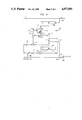
- FIG. 4 The model echo path used in the nonlinear echo canceller of the present invention is illustrated in FIG. 4. As shown in FIG. 4, a symbol of the transmitting data signal X(k) is first operated on by the nonlinear function ⁇ (box 60) to form
- a transmitting signal vector Y k is formed such that ##EQU4## i.e. Y k is formed from the n most recent values of the signal Y(k) through use of the unit delay elements 62 shown in FIG. 4.
- the products h i ,k Y(k.i+1) are formed in FIG. 4 by the multiplier units 64 and the products are summed by the addition unit 66 to form the estimated echo signal e(k).
- the same LMS algorithm is used to adaptively update both the nonlinear function ⁇ and the estimated linear echo path finite impulse response H k .
- the operation of the nonlinear dual mode LMS echo canceller of the present invention is divided up into two phases, a startup phase and a dual mode phase.
- the operation for the startup phase is the same as that of a conventional linear LMS echo canceller.
- the echo canceller estimates the linear echo path finite impulse response H k by executing the following expression based on training X k 's.
- the echo canceller switches to the dual mode phase.
- the echo canceller utilizes an LMS algorithm to both provide an estimate f(X k ) k of the nonlinear function f(X k ) k where ##EQU5## and to update H k .
- the echo canceller In the dual mode phase, the echo canceller normally executes the following nonlinear function estimation operation and lets H k remain unchanged:
- the function f(.) on the right hand side of equation 14 stands for a memory fetch operation with the argument vector X k providing the addresses
- the function f(.) stands for a memory update operation with the argument vector X k providing the addresses. For each iteration k, there are n memory fetch and n memory update operations.
- the echo canceller updates the estimated linear echo path finite impulse response H k while keeping f(X k ) k constant through use of the following equations.
- the number M is illustratively chosen between 2 and 5.
- the estimated echo signal is given by
- FIG. 5 A schematic diagram of a nonlinear dual mode echo canceller 30' in accordance with an illustrative embodiment of the invention is shown in FIG. 5.
- the echo canceller 30' is data driven.
- the echo canceller 30' receives as its input via line 32 the signal X(k).
- the combined signal y(k) which includes both the data signal to be received r(k) and the echo signal e(k), is present on the two-wire pair 13b.
- the echo canceller 30' of FIG. 5 produces as an output on line 90 an estimated echo signal e(k).
- the estimated echo signal e(k) takes into account the nonlinear echo path component in the manner described above.
- the estimated echo signal e(k) is subtracted from y(k) through use of the subtraction unit 91 to produce a signal r(k)+e(k)-e(k) which is the best possible approximation to r(k). This latter signal is then transmitted to the receiver 12b of the modem 12 (see FIG. 2).
- the echo canceller 30' also includes the shift register 50 and non-shift register 52 both of which are of length n.
- the shift register 50 stores the data vector X k and the shift register 52 stores the estimated linear echo path finite impulse response H k .
- the random access memory 94 stores the values of the vector f(X k ) k .
- values of f(X k ) k+1 are written into the random access memory 94 via line 93 using the values of X k on line 95 as addresses.
- values of f(X k ) k are read from the memory via line 96 using the values of X k as addresses.
- the echo canceller 30' further includes the switch mechanism 98 which can switch between the positions a and b shown in FIG. 5.
- the switch position a is used for the nonlinear function estimation task and the switch position b is used for the estimation of the linear echo path impulse response.
- operation of the nonlinear echo canceler is divided into a startup phase and a dual mode phase.
- the startup phase the nonlinear echo path as represented by the function f(.) is not taken into account and the values f(X(k)) may be viewed as being equal to zero.
- the multiplication unit 99 utilizes training X(k)'s to form the product X k T H k corresponding to the estimated echo signal e(k).
- the signal r(k)+e(k)-e(h) is multiplied by ⁇ using the scaler amplifier-multiplier unit 100 and by the vector X k using the multiplier unit 101 to update the values of H k (i.e. to form H k+1 ) in accordance with Eq (12) above.
- the LMS algorithm reaches a minimum mean square error determined by the echo path nonlinearly.
- the echo canceller switches into the dual phase mode.
- the switch mechanism 98 assumes the position b and the linear echo path impulse response H k remains constant while the vector f(X k ) k corresponding to the nonlinear part of the echo path is estimated through use of the signal processing operations represented by equation (14). More particularly, the vector quantity X k +f(X k ) k is formed by accessing the vector f(X k ) k from the memory 94 and adding thereto through use of the addition unit 102 the vector X k .
- the multiplier unit 99 then provides the product
- the signal r(k)+e(k)-e(h) is formed using the subtraction unit 91 and is multiplied by the step size ⁇ using the scaler multiplication unit 105 and by H k using the multiplication unit 103.
- the resulting signal is then added to f(X k ) k using the addition unit 107 to form f(X k ) k+1 whose values are written into the memory 94 via line 93.
- the values f(X k ) k are held constant and the values of H k are updated according to Eq. (17) by switching the switch mechanism 98 into position b and using the units 102, 99, 91, 100 and 101 to form the vector ⁇ (X k +f(X k ) k )(r(k)+e(k)-e(k)) which is then added H k to form H k+1 .
- FIG. 6 can be utilized to compare the performance of a conventional linear LMS echo canceller with the performance of the dual mode nonlinear echo canceller of the present invention.
- the abscissa is the number of iterations and the ordinate is the mean square error in decibels.
- the solid curve 200 plots the mean square error of a conventional linear LMS echo canceller as a function of the number of iterations.
- the broken curve 300 plots the mean square error of the nonlinear dual mode echo canceller as a function of the number of iterations.
- n (the length of the echo canceller filter) is 20
- the adaptation step size ⁇ for the linear echo path impulse response estimation is taken to be 0.005
- the function f(X(k)) is taken to be bX(k) 2 where b is 0.001
- the adaptation step size ⁇ for the nonlinear function estimation is taken to be 0.5
- M is set equal to 3.
- the mean square error of the linear LMS echo canceller reaches a minimum of -60 dB after about 200 iterations.
- operation in the dual mode phase followsing completion of the startup phase
- a mean square error below -100 dB.
- the convergence time ⁇ dual of the inventive dual mode nonlinear echo cancellation is approximately M times longer than the convergence time ⁇ LMS of a conventional linear LMS echo canceller, i.e.
- M is typically chosen between 2 and 5.
- an adaptive data driven nonlinear echo canceller is disclosed. Unlike other approaches to nonlinear echo cancellation, the inventive echo canceller models the nonlinearity of the echo path as a nonlinear function with no delay, while the linear portion of the echo path is modelled using a finite impulse response. In comparison to a conventional LMS linear echo canceller, the inventive nonlinear echo canceller utilizes only an additional small random access memory to store values of the nonlinear function used to model the nonlinear component of the echo path.
- Operation of the inventive echo canceller is divided into a startup phase and a dual mode phase.
- operation is the same as the conventional LMS linear echo canceller wherein an LMS algorithm is used to iteratively estimate the linear echo path impulse response.
- the LMS algorithm is used to estimate both the nonlinear function characteristic of the nonlinear echo path and the finite impulse response characteristic of the linear echo path.
- the nonlinear echo canceller normally estimates the nonlinear function while the finite impulse response is held constant. Periodically, the nonlinear function is held constant and the estimated finite impulse response is updated.
Abstract
Description
H.sub.o -0 (4)
H.sub.k+1 -H.sub.k +μX.sub.k (y(k)-X.sub.k.sup.T H.sub.k) k<o (5)
ξ.sub.k -E[e(k)-e(k)].sup.2 (6)
Y(k)-ψ(x(k))-X(k)+f(X(k)). (9)
e(h)=H.sub.k.sup.T Y.sub.k -Σh.sub.i,k Y(k.1)=Y.sub.k.sup.T H.sub.k (11)
H.sub.k+1 -H.sub.k +μX.sub.k (y(k)-X.sub.k.sup.T H.sub.k)(12)
f(X.sub.k).sub.k+1 =f(X.sub.k).sub.k +βH.sub.k (y(k)-H.sub.k.sup.T (X.sub.k +f(X.sub.k).sub.k) (14)
H.sub.k+1 =H.sub.k (15)
f(X.sub.nc)=0
H.sub.k+1 =H.sub.k +μ(X.sub.k +f(X.sub.k).sub.k)(y(k)-H.sub.k.sup.T (X.sub.k +f(X.sub.k).sub.k)) (17)
f(X.sub.k).sub.k+1 =f(X.sub.k).sub.k (18)
e(h)=H.sub.k.sup.T (X.sub.k +f(X.sub.k).sub.k)=(x.sub.k +f(X.sub.k).sub.k).sup.T H.sub.k (19)
e(h)=(X.sub.k +f(X.sub.k).sub.k).sup.T H.sub.k (20)
τ.sub.dual =Mτ.sub.LMS (21)
Claims (14)
Priority Applications (1)
| Application Number | Priority Date | Filing Date | Title |
|---|---|---|---|
| US07/438,598 US4977591A (en) | 1989-11-17 | 1989-11-17 | Dual mode LMS nonlinear data echo canceller |
Applications Claiming Priority (1)
| Application Number | Priority Date | Filing Date | Title |
|---|---|---|---|
| US07/438,598 US4977591A (en) | 1989-11-17 | 1989-11-17 | Dual mode LMS nonlinear data echo canceller |
Publications (1)
| Publication Number | Publication Date |
|---|---|
| US4977591A true US4977591A (en) | 1990-12-11 |
Family
ID=23741267
Family Applications (1)
| Application Number | Title | Priority Date | Filing Date |
|---|---|---|---|
| US07/438,598 Expired - Lifetime US4977591A (en) | 1989-11-17 | 1989-11-17 | Dual mode LMS nonlinear data echo canceller |
Country Status (1)
| Country | Link |
|---|---|
| US (1) | US4977591A (en) |
Cited By (46)
| Publication number | Priority date | Publication date | Assignee | Title |
|---|---|---|---|---|
| US5111481A (en) * | 1989-11-17 | 1992-05-05 | Nynex Corporation | Dual mode LMS channel equalizer |
| US5148427A (en) * | 1990-04-10 | 1992-09-15 | Level One Communications, Inc. | Non-linear echo canceller |
| US5189637A (en) * | 1989-04-27 | 1993-02-23 | Telefonaktiebolaget L M Ericsson | Method and apparatus for preventing erroneous echoelimination and equalization |
| US5267152A (en) * | 1989-10-28 | 1993-11-30 | Yang Won S | Non-invasive method and apparatus for measuring blood glucose concentration |
| US5329587A (en) * | 1993-03-12 | 1994-07-12 | At&T Bell Laboratories | Low-delay subband adaptive filter |
| US5329586A (en) * | 1992-05-29 | 1994-07-12 | At&T Bell Laboratories | Nonlinear echo canceller for data signals using a non-redundant distributed lookup-table architecture |
| US5452289A (en) * | 1993-01-08 | 1995-09-19 | Multi-Tech Systems, Inc. | Computer-based multifunction personal communications system |
| US5535204A (en) * | 1993-01-08 | 1996-07-09 | Multi-Tech Systems, Inc. | Ringdown and ringback signalling for a computer-based multifunction personal communications system |
| US5546395A (en) * | 1993-01-08 | 1996-08-13 | Multi-Tech Systems, Inc. | Dynamic selection of compression rate for a voice compression algorithm in a voice over data modem |
| DE19525382A1 (en) * | 1995-07-12 | 1997-01-16 | Deutsche Telekom Ag | Stepping width controlling method esp. for echo canceller with adaptive filter - calculating optimum stepping width from quotient of estimated values for dispersal of input and error signals |
| DE19525381A1 (en) * | 1995-07-12 | 1997-01-16 | Deutsche Telekom Ag | Echo canceller stepping width controlling method - using quotient of estimated values of dispersal of input signal and error signal, multiplied by squared norm of cross correlation coefficient vectors and squared input signal level |
| US5617423A (en) * | 1993-01-08 | 1997-04-01 | Multi-Tech Systems, Inc. | Voice over data modem with selectable voice compression |
| US5619508A (en) * | 1993-01-08 | 1997-04-08 | Multi-Tech Systems, Inc. | Dual port interface for a computer-based multifunction personal communication system |
| DE19543666A1 (en) * | 1995-11-23 | 1997-05-28 | Sel Alcatel Ag | Echo canceller |
| US5682386A (en) * | 1994-04-19 | 1997-10-28 | Multi-Tech Systems, Inc. | Data/voice/fax compression multiplexer |
| US5754589A (en) * | 1993-01-08 | 1998-05-19 | Multi-Tech Systems, Inc. | Noncompressed voice and data communication over modem for a computer-based multifunction personal communications system |
| US5757801A (en) * | 1994-04-19 | 1998-05-26 | Multi-Tech Systems, Inc. | Advanced priority statistical multiplexer |
| WO1998036493A2 (en) * | 1997-02-14 | 1998-08-20 | Tellabs Oy | Method of correcting the symbol shape error of multilevel pulses in baseband transmission caused by the use of pulse-rate modulation |
| US5812534A (en) * | 1993-01-08 | 1998-09-22 | Multi-Tech Systems, Inc. | Voice over data conferencing for a computer-based personal communications system |
| WO1998044650A1 (en) | 1997-03-31 | 1998-10-08 | Conexant Systems, Inc. | Orthogonal lms algorithms for fast line echo canceler training |
| US5864560A (en) * | 1993-01-08 | 1999-01-26 | Multi-Tech Systems, Inc. | Method and apparatus for mode switching in a voice over data computer-based personal communications system |
| US6009082A (en) * | 1993-01-08 | 1999-12-28 | Multi-Tech Systems, Inc. | Computer-based multifunction personal communication system with caller ID |
| GB2341066A (en) * | 1998-08-20 | 2000-03-01 | Mitel Corp | Adaptive echo canceller removes non-linear signals |
| US6317419B1 (en) * | 1998-06-10 | 2001-11-13 | Conexant Systems, Inc. | Method and apparatus for training an echo canceler in a PCM modem context |
| WO2003017561A1 (en) * | 2001-08-16 | 2003-02-27 | Globespan Virata Incorporated | Apparatus and method for concealing the loss of audio samples |
| US20030140075A1 (en) * | 2002-01-23 | 2003-07-24 | Fabian Lis | Echo canceller having an adaptive filter with a dynamically adjustable step size |
| US6687235B1 (en) | 2000-01-21 | 2004-02-03 | Adtran, Inc. | Mitigation of non-linear signal perturbations using truncated volterra-based non-linear echo canceler |
| US6754187B1 (en) | 2000-04-06 | 2004-06-22 | Inter-Tel, Inc. | Performance enhancement system for digital PBX |
| US20050207346A1 (en) * | 2004-03-04 | 2005-09-22 | Fred Chu | System and method for detecting non-linear distortion of signals communicated across telecommunication lines |
| US20060062379A1 (en) * | 2004-09-22 | 2006-03-23 | Hossein Sedarat | Methods and apparatuses for detecting and reducing non-linear echo in a multi-carrier communication system |
| US20060115077A1 (en) * | 1997-11-14 | 2006-06-01 | Laberteaux Kenneth P | Echo canceller employing dual-H architecture having variable adaptive gain settings |
| US20060140393A1 (en) * | 1997-11-14 | 2006-06-29 | Laberteaux Kenneth P | Echo canceller employing dual-H architecture having improved non-linear echo path detection |
| US7310425B1 (en) * | 1999-12-28 | 2007-12-18 | Agere Systems Inc. | Multi-channel frequency-domain adaptive filter method and apparatus |
| US20080267327A1 (en) * | 2002-07-03 | 2008-10-30 | Xiaopeng Chen | Nonlinear echo compensator for class B transmitter line driver |
| US20100142604A1 (en) * | 2008-12-09 | 2010-06-10 | Yehuda Azenkot | Method and apparatus of frequency domain echo canceller |
| US7813439B2 (en) | 2006-02-06 | 2010-10-12 | Broadcom Corporation | Various methods and apparatuses for impulse noise detection |
| US7852950B2 (en) | 2005-02-25 | 2010-12-14 | Broadcom Corporation | Methods and apparatuses for canceling correlated noise in a multi-carrier communication system |
| US7953163B2 (en) | 2004-11-30 | 2011-05-31 | Broadcom Corporation | Block linear equalization in a multicarrier communication system |
| US8194722B2 (en) | 2004-10-11 | 2012-06-05 | Broadcom Corporation | Various methods and apparatuses for impulse noise mitigation |
| US8472533B2 (en) | 2008-10-10 | 2013-06-25 | Broadcom Corporation | Reduced-complexity common-mode noise cancellation system for DSL |
| US9172816B2 (en) | 2013-05-31 | 2015-10-27 | Microsoft Technology Licensing, Llc | Echo suppression |
| US9277059B2 (en) | 2013-05-31 | 2016-03-01 | Microsoft Technology Licensing, Llc | Echo removal |
| US9374257B2 (en) | 2005-03-18 | 2016-06-21 | Broadcom Corporation | Methods and apparatuses of measuring impulse noise parameters in multi-carrier communication systems |
| US9467571B2 (en) | 2013-05-31 | 2016-10-11 | Microsoft Technology Licensing, Llc | Echo removal |
| US9521264B2 (en) | 2013-05-31 | 2016-12-13 | Microsoft Technology Licensing, Llc | Echo removal |
| CN108028983A (en) * | 2015-09-11 | 2018-05-11 | 思睿逻辑国际半导体有限公司 | Nonlinear acoustics echo cancellor based on transducer impedance |
Citations (2)
| Publication number | Priority date | Publication date | Assignee | Title |
|---|---|---|---|---|
| US4064379A (en) * | 1976-06-11 | 1977-12-20 | Communications Satellite Corporation | Logarithmic echo canceller |
| US4669116A (en) * | 1982-12-09 | 1987-05-26 | Regents Of The University Of California | Non-linear echo cancellation of data signals |
-
1989
- 1989-11-17 US US07/438,598 patent/US4977591A/en not_active Expired - Lifetime
Patent Citations (2)
| Publication number | Priority date | Publication date | Assignee | Title |
|---|---|---|---|---|
| US4064379A (en) * | 1976-06-11 | 1977-12-20 | Communications Satellite Corporation | Logarithmic echo canceller |
| US4669116A (en) * | 1982-12-09 | 1987-05-26 | Regents Of The University Of California | Non-linear echo cancellation of data signals |
Non-Patent Citations (8)
| Title |
|---|
| "Subscriber Lines", IEEE Trans. Commun., vol. COM-29, No. 11, pp. 1573-1580. |
| E. J. Thomas, "Some Considerations on the Application of the Volterra Representation of Nonlinear Networks to Adaptive Echo Cancellers", B.S.T.J. vol. 50, No. 8, pp. 2797-2805, Oct. 1971. |
| E. J. Thomas, Some Considerations on the Application of the Volterra Representation of Nonlinear Networks to Adaptive Echo Cancellers , B.S.T.J. vol. 50, No. 8, pp. 2797 2805, Oct. 1971. * |
| N. H. Holte and S. Stueflotten, "A New Digital Echo Cancelle- for Two-Wire". |
| N. H. Holte and S. Stueflotten, A New Digital Echo Cancelle for Two Wire . * |
| O. Agazzi, D. G. Messerschmitt, and D. A. Hodges, "Nonlinear Echo Cancellation of Data Signals", IEEE Trans. Commun., vol. COM-30, pp. 2421-2433, Nov. 1982. |
| O. Agazzi, D. G. Messerschmitt, and D. A. Hodges, Nonlinear Echo Cancellation of Data Signals , IEEE Trans. Commun., vol. COM 30, pp. 2421 2433, Nov. 1982. * |
| Subscriber Lines IEEE Trans. Commun., vol. COM 29, No. 11, pp. 1573 1580. * |
Cited By (79)
| Publication number | Priority date | Publication date | Assignee | Title |
|---|---|---|---|---|
| US5189637A (en) * | 1989-04-27 | 1993-02-23 | Telefonaktiebolaget L M Ericsson | Method and apparatus for preventing erroneous echoelimination and equalization |
| US5267152A (en) * | 1989-10-28 | 1993-11-30 | Yang Won S | Non-invasive method and apparatus for measuring blood glucose concentration |
| US5111481A (en) * | 1989-11-17 | 1992-05-05 | Nynex Corporation | Dual mode LMS channel equalizer |
| US5148427A (en) * | 1990-04-10 | 1992-09-15 | Level One Communications, Inc. | Non-linear echo canceller |
| US5329586A (en) * | 1992-05-29 | 1994-07-12 | At&T Bell Laboratories | Nonlinear echo canceller for data signals using a non-redundant distributed lookup-table architecture |
| US5592586A (en) * | 1993-01-08 | 1997-01-07 | Multi-Tech Systems, Inc. | Voice compression system and method |
| US6009082A (en) * | 1993-01-08 | 1999-12-28 | Multi-Tech Systems, Inc. | Computer-based multifunction personal communication system with caller ID |
| US5471470A (en) * | 1993-01-08 | 1995-11-28 | Multi-Tech Systems, Inc. | Computer-based multifunction personal communications system |
| US5500859A (en) * | 1993-01-08 | 1996-03-19 | Multi-Tech Systems, Inc. | Voice and data transmission system |
| US5535204A (en) * | 1993-01-08 | 1996-07-09 | Multi-Tech Systems, Inc. | Ringdown and ringback signalling for a computer-based multifunction personal communications system |
| US5546395A (en) * | 1993-01-08 | 1996-08-13 | Multi-Tech Systems, Inc. | Dynamic selection of compression rate for a voice compression algorithm in a voice over data modem |
| US5559793A (en) * | 1993-01-08 | 1996-09-24 | Multi-Tech Systems, Inc. | Echo cancellation system and method |
| US5574725A (en) * | 1993-01-08 | 1996-11-12 | Multi-Tech Systems, Inc. | Communication method between a personal computer and communication module |
| US5577041A (en) * | 1993-01-08 | 1996-11-19 | Multi-Tech Systems, Inc. | Method of controlling a personal communication system |
| US5790532A (en) * | 1993-01-08 | 1998-08-04 | Multi-Tech Systems, Inc. | Voice over video communication system |
| US5764628A (en) * | 1993-01-08 | 1998-06-09 | Muti-Tech Systemns, Inc. | Dual port interface for communication between a voice-over-data system and a conventional voice system |
| US5452289A (en) * | 1993-01-08 | 1995-09-19 | Multi-Tech Systems, Inc. | Computer-based multifunction personal communications system |
| US5600649A (en) * | 1993-01-08 | 1997-02-04 | Multi-Tech Systems, Inc. | Digital simultaneous voice and data modem |
| US5617423A (en) * | 1993-01-08 | 1997-04-01 | Multi-Tech Systems, Inc. | Voice over data modem with selectable voice compression |
| US5619508A (en) * | 1993-01-08 | 1997-04-08 | Multi-Tech Systems, Inc. | Dual port interface for a computer-based multifunction personal communication system |
| US5864560A (en) * | 1993-01-08 | 1999-01-26 | Multi-Tech Systems, Inc. | Method and apparatus for mode switching in a voice over data computer-based personal communications system |
| US5673257A (en) * | 1993-01-08 | 1997-09-30 | Multi-Tech Systems, Inc. | Computer-based multifunction personal communication system |
| US5673268A (en) * | 1993-01-08 | 1997-09-30 | Multi-Tech Systems, Inc. | Modem resistant to cellular dropouts |
| US5815503A (en) * | 1993-01-08 | 1998-09-29 | Multi-Tech Systems, Inc. | Digital simultaneous voice and data mode switching control |
| US5754589A (en) * | 1993-01-08 | 1998-05-19 | Multi-Tech Systems, Inc. | Noncompressed voice and data communication over modem for a computer-based multifunction personal communications system |
| US5812534A (en) * | 1993-01-08 | 1998-09-22 | Multi-Tech Systems, Inc. | Voice over data conferencing for a computer-based personal communications system |
| US5764627A (en) * | 1993-01-08 | 1998-06-09 | Multi-Tech Systems, Inc. | Method and apparatus for a hands-free speaker phone |
| US5329587A (en) * | 1993-03-12 | 1994-07-12 | At&T Bell Laboratories | Low-delay subband adaptive filter |
| US6151333A (en) * | 1994-04-19 | 2000-11-21 | Multi-Tech Systems, Inc. | Data/voice/fax compression multiplexer |
| US5757801A (en) * | 1994-04-19 | 1998-05-26 | Multi-Tech Systems, Inc. | Advanced priority statistical multiplexer |
| US5682386A (en) * | 1994-04-19 | 1997-10-28 | Multi-Tech Systems, Inc. | Data/voice/fax compression multiplexer |
| US6515984B1 (en) | 1994-04-19 | 2003-02-04 | Multi-Tech Systems, Inc. | Data/voice/fax compression multiplexer |
| US6570891B1 (en) | 1994-04-19 | 2003-05-27 | Multi-Tech Systems, Inc. | Advanced priority statistical multiplexer |
| US6275502B1 (en) | 1994-04-19 | 2001-08-14 | Multi-Tech Systems, Inc. | Advanced priority statistical multiplexer |
| DE19525382A1 (en) * | 1995-07-12 | 1997-01-16 | Deutsche Telekom Ag | Stepping width controlling method esp. for echo canceller with adaptive filter - calculating optimum stepping width from quotient of estimated values for dispersal of input and error signals |
| DE19525382B4 (en) * | 1995-07-12 | 2005-12-22 | Deutsche Telekom Ag | Method for controlling the step size of an adaptive-filter echo canceller |
| DE19525381B4 (en) * | 1995-07-12 | 2006-01-05 | Deutsche Telekom Ag | Method for controlling the step size of an adaptive-filter echo canceller |
| DE19525381A1 (en) * | 1995-07-12 | 1997-01-16 | Deutsche Telekom Ag | Echo canceller stepping width controlling method - using quotient of estimated values of dispersal of input signal and error signal, multiplied by squared norm of cross correlation coefficient vectors and squared input signal level |
| DE19543666A1 (en) * | 1995-11-23 | 1997-05-28 | Sel Alcatel Ag | Echo canceller |
| US5799078A (en) * | 1995-11-23 | 1998-08-25 | Alcatel Alsthom Compagnie Generale D'electricite | Echo canceller |
| WO1998036493A2 (en) * | 1997-02-14 | 1998-08-20 | Tellabs Oy | Method of correcting the symbol shape error of multilevel pulses in baseband transmission caused by the use of pulse-rate modulation |
| WO1998036493A3 (en) * | 1997-02-14 | 1998-11-12 | Tellabs Oy | Method of correcting the symbol shape error of multilevel pulses in baseband transmission caused by the use of pulse-rate modulation |
| US5909426A (en) * | 1997-03-31 | 1999-06-01 | Rockwell Science Center, Inc. | Orthogonal LMS algorithms for fast line echo canceler training |
| WO1998044650A1 (en) | 1997-03-31 | 1998-10-08 | Conexant Systems, Inc. | Orthogonal lms algorithms for fast line echo canceler training |
| US20060140393A1 (en) * | 1997-11-14 | 2006-06-29 | Laberteaux Kenneth P | Echo canceller employing dual-H architecture having improved non-linear echo path detection |
| US7450713B2 (en) * | 1997-11-14 | 2008-11-11 | Tellabs Operations, Inc. | Echo canceller employing dual-H architecture having improved non-linear echo path detection |
| US20060115077A1 (en) * | 1997-11-14 | 2006-06-01 | Laberteaux Kenneth P | Echo canceller employing dual-H architecture having variable adaptive gain settings |
| US6317419B1 (en) * | 1998-06-10 | 2001-11-13 | Conexant Systems, Inc. | Method and apparatus for training an echo canceler in a PCM modem context |
| GB2341066A (en) * | 1998-08-20 | 2000-03-01 | Mitel Corp | Adaptive echo canceller removes non-linear signals |
| US7693291B2 (en) | 1999-12-28 | 2010-04-06 | Agere Systems Inc. | Multi-channel frequency-domain adaptive filter method and apparatus |
| US20080118075A1 (en) * | 1999-12-28 | 2008-05-22 | Agere Systems Inc. | Multi-Channel Frequency-Domain Adaptive Filter Method and Apparatus |
| US7310425B1 (en) * | 1999-12-28 | 2007-12-18 | Agere Systems Inc. | Multi-channel frequency-domain adaptive filter method and apparatus |
| US6687235B1 (en) | 2000-01-21 | 2004-02-03 | Adtran, Inc. | Mitigation of non-linear signal perturbations using truncated volterra-based non-linear echo canceler |
| US6754187B1 (en) | 2000-04-06 | 2004-06-22 | Inter-Tel, Inc. | Performance enhancement system for digital PBX |
| WO2003017561A1 (en) * | 2001-08-16 | 2003-02-27 | Globespan Virata Incorporated | Apparatus and method for concealing the loss of audio samples |
| US6950842B2 (en) * | 2002-01-23 | 2005-09-27 | Analog Devices, Inc. | Echo canceller having an adaptive filter with a dynamically adjustable step size |
| US20030140075A1 (en) * | 2002-01-23 | 2003-07-24 | Fabian Lis | Echo canceller having an adaptive filter with a dynamically adjustable step size |
| US8989251B2 (en) | 2002-07-03 | 2015-03-24 | Marvell International Ltd. | Method and apparatus to compensate for nonlinear echo in an output of a current source |
| US8743939B2 (en) * | 2002-07-03 | 2014-06-03 | Marvell International Ltd. | Nonlinear echo compensator for class B transmitter line driver |
| US20080267327A1 (en) * | 2002-07-03 | 2008-10-30 | Xiaopeng Chen | Nonlinear echo compensator for class B transmitter line driver |
| US7634032B2 (en) | 2004-03-04 | 2009-12-15 | Adtran, Inc. | System and method for detecting non-linear distortion of signals communicated across telecommunication lines |
| US20050207346A1 (en) * | 2004-03-04 | 2005-09-22 | Fred Chu | System and method for detecting non-linear distortion of signals communicated across telecommunication lines |
| US7177419B2 (en) * | 2004-09-22 | 2007-02-13 | 2Wire, Inc. | Methods and apparatuses for detecting and reducing non-linear echo in a multi-carrier communication system |
| US20060062379A1 (en) * | 2004-09-22 | 2006-03-23 | Hossein Sedarat | Methods and apparatuses for detecting and reducing non-linear echo in a multi-carrier communication system |
| US8194722B2 (en) | 2004-10-11 | 2012-06-05 | Broadcom Corporation | Various methods and apparatuses for impulse noise mitigation |
| US7953163B2 (en) | 2004-11-30 | 2011-05-31 | Broadcom Corporation | Block linear equalization in a multicarrier communication system |
| US7852950B2 (en) | 2005-02-25 | 2010-12-14 | Broadcom Corporation | Methods and apparatuses for canceling correlated noise in a multi-carrier communication system |
| US9374257B2 (en) | 2005-03-18 | 2016-06-21 | Broadcom Corporation | Methods and apparatuses of measuring impulse noise parameters in multi-carrier communication systems |
| US7813439B2 (en) | 2006-02-06 | 2010-10-12 | Broadcom Corporation | Various methods and apparatuses for impulse noise detection |
| US8605837B2 (en) | 2008-10-10 | 2013-12-10 | Broadcom Corporation | Adaptive frequency-domain reference noise canceller for multicarrier communications systems |
| US8472533B2 (en) | 2008-10-10 | 2013-06-25 | Broadcom Corporation | Reduced-complexity common-mode noise cancellation system for DSL |
| US9160381B2 (en) | 2008-10-10 | 2015-10-13 | Broadcom Corporation | Adaptive frequency-domain reference noise canceller for multicarrier communications systems |
| US8619897B2 (en) | 2008-12-09 | 2013-12-31 | Netlogic Microsystems, Inc. | Method and apparatus of frequency domain echo canceller |
| US20100142604A1 (en) * | 2008-12-09 | 2010-06-10 | Yehuda Azenkot | Method and apparatus of frequency domain echo canceller |
| US9172816B2 (en) | 2013-05-31 | 2015-10-27 | Microsoft Technology Licensing, Llc | Echo suppression |
| US9277059B2 (en) | 2013-05-31 | 2016-03-01 | Microsoft Technology Licensing, Llc | Echo removal |
| US9467571B2 (en) | 2013-05-31 | 2016-10-11 | Microsoft Technology Licensing, Llc | Echo removal |
| US9521264B2 (en) | 2013-05-31 | 2016-12-13 | Microsoft Technology Licensing, Llc | Echo removal |
| CN108028983A (en) * | 2015-09-11 | 2018-05-11 | 思睿逻辑国际半导体有限公司 | Nonlinear acoustics echo cancellor based on transducer impedance |
Similar Documents
| Publication | Publication Date | Title |
|---|---|---|
| US4977591A (en) | Dual mode LMS nonlinear data echo canceller | |
| US4736414A (en) | Method of and device for the digital cancellation of the echo generated in connections with time-varying characteristics | |
| US5111481A (en) | Dual mode LMS channel equalizer | |
| US4268727A (en) | Adaptive digital echo cancellation circuit | |
| US4682358A (en) | Echo canceller | |
| US5920548A (en) | Echo path delay estimation | |
| CA1063744A (en) | Echo canceller for two-wire pull duplex data transmission | |
| US5859907A (en) | Echo canceler and echo path estimating method | |
| US4131767A (en) | Echo cancellation in two-wire, two-way data transmission systems | |
| US4362909A (en) | Echo canceler with high-pass filter | |
| US4621173A (en) | Method of reducing the convergence time of an echo canceller and apparatus for carrying out said method | |
| US4742510A (en) | Near and far echo canceller for data communications | |
| US5319585A (en) | High resolution filtering using low resolution processors | |
| US5351291A (en) | Adaptive echo cancellation method and device for implementing said method | |
| WO1992009158A1 (en) | Frequency domain adaptive echo canceller for full-duplex data transmission | |
| US5815496A (en) | Cascade echo canceler arrangement | |
| US7068780B1 (en) | Hybrid echo canceller | |
| US4615025A (en) | Data transmission system | |
| JPH0136737B2 (en) | ||
| US5909426A (en) | Orthogonal LMS algorithms for fast line echo canceler training | |
| US4594479A (en) | Fast start-up of adaptive echo canceler or echo measurement device | |
| US20030081763A1 (en) | Efficient echo channel, estimation mechanism for an ADSL echo canceller | |
| EP0246425B1 (en) | Apparatus for cancelling echoes in a duplex digital transmission system | |
| US5303228A (en) | A far-end echo canceller with a digital filter for simulating a far end echo containing a frequency offset | |
| US5461582A (en) | Filter for 2B1Q signals |
Legal Events
| Date | Code | Title | Description |
|---|---|---|---|
| AS | Assignment |
Owner name: NYNEX CORPORATION, A CORP OF DE, NEW YORK Free format text: ASSIGNMENT OF ASSIGNORS INTEREST.;ASSIGNOR:CHEN, WALTER YI-CHEN;REEL/FRAME:005200/0532 Effective date: 19891114 Owner name: NYNEX CORPORATION, A CORP OF DE, NEW YORK Free format text: ASSIGNMENT OF ASSIGNORS INTEREST.;ASSIGNOR:HADDAD, RICHARD A.;REEL/FRAME:005200/0530 Effective date: 19891109 |
|
| STCF | Information on status: patent grant |
Free format text: PATENTED CASE |
|
| FPAY | Fee payment |
Year of fee payment: 4 |
|
| FPAY | Fee payment |
Year of fee payment: 8 |
|
| FPAY | Fee payment |
Year of fee payment: 12 |
|
| AS | Assignment |
Owner name: NYNEX LLC, NEW YORK Free format text: CONVERSION;ASSIGNOR:NYNEX CORPORATION;REEL/FRAME:032777/0125 Effective date: 20111031 |
|
| AS | Assignment |
Owner name: VERIZON PATENT AND LICENSING INC., NEW JERSEY Free format text: ASSIGNMENT OF ASSIGNORS INTEREST;ASSIGNOR:NYNEX LLC;REEL/FRAME:032890/0505 Effective date: 20140409 |