US4975009A - Bolt and wedge assembly for panel units - Google Patents
Bolt and wedge assembly for panel units Download PDFInfo
- Publication number
- US4975009A US4975009A US07/356,254 US35625489A US4975009A US 4975009 A US4975009 A US 4975009A US 35625489 A US35625489 A US 35625489A US 4975009 A US4975009 A US 4975009A
- Authority
- US
- United States
- Prior art keywords
- bolt
- passage
- wedge
- engaging member
- assembly
- Prior art date
- Legal status (The legal status is an assumption and is not a legal conclusion. Google has not performed a legal analysis and makes no representation as to the accuracy of the status listed.)
- Expired - Lifetime
Links
Images
Classifications
-
- E—FIXED CONSTRUCTIONS
- E04—BUILDING
- E04G—SCAFFOLDING; FORMS; SHUTTERING; BUILDING IMPLEMENTS OR AIDS, OR THEIR USE; HANDLING BUILDING MATERIALS ON THE SITE; REPAIRING, BREAKING-UP OR OTHER WORK ON EXISTING BUILDINGS
- E04G17/00—Connecting or other auxiliary members for forms, falsework structures, or shutterings
- E04G17/04—Connecting or fastening means for metallic forming or stiffening elements, e.g. for connecting metallic elements to non-metallic elements
- E04G17/045—Connecting or fastening means for metallic forming or stiffening elements, e.g. for connecting metallic elements to non-metallic elements being tensioned by wedge-shaped elements
Definitions
- the present invention relates to retainers for holding together concrete wall forms of panel unit type. More particularly, the present invention relates to a bolt and wedge assembly in which the bolt is disposed within a support member resists slidable movement of the bolt, and the position of the bolt is disengagably fixable.
- Concrete wall forms are in common usage in the art for forming pourable concrete walls. Such concrete wall forms normally have transverse flanges extending outwardly thereform for alignment with adjacent wall forms.
- Trimmer U.S. Pat. No. 3,447,771 discloses a reinforcement for concrete wall form connectors in which reinforcing plates are placed on tranverse flanges of prefabricated panels, allowing the panels to be fixedly attached to one another in preparatiion to form a concrete wall. Alignable apertures are formed within these plates and a pin member fits in the aligned apertures to fix them in an aligned relationship.
- the pin member has a slot formed transversely therein and a wedge is insertable in the slot to retain two prefabricated panels in an aligned configuration.
- U.S. Pat. No. 4,194,717 was issued to the present inventors for a wedge and bolt assembly for panel units, and discloses a blot assembly which is attached to a first prefabricated panel by a bolt support, which slidably supports the bolt.
- a single annular groove is provided around the circumference of the bolt to accept a wedge therein and to fix the bolt in a retracted position for disassembly or storage of the panel unit when a wall is completed.
- the disclosure of U.S. Pat. No. 4,194,717 is here incorporated by reference.
- the present invention provides an improved wedge and bolt assembly for connecting a first prefabricated panel to a second prefabricated panel wherein the first prefabricated panel has a first flange extending outwardly therefrom with a first aperture formed therethrough, and the second panel has a second flange extending outwardly therefrom with a second aperture formed therethrough which is alignable with the first aperture.
- a bolt and wedge assembly in accordance with the present invention in a particular embodiment thereof, comprises:
- a support body having a first hollow passage formed therethrough for slidably receiving the bolt, the bolt support member being mountable on the first or second prefabricated panel, the support body having a second hollow passage formed therein which is substantially transverse to the first hollow passage and communicates therewith;
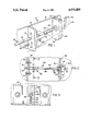
- FIG. 1 is a perspective view of a wedge and bolt assembly in accordance with the present invention
- FIG. 2 is a cross section view of the assembly of FIG. 1;
- FIG. 3 is a side plan view partially in cross section, of the bolt support member, taken along the line 3-3 of FIG. 2.
- a number of prefabricated panel units are joined together in an edge-to-edge relationship to create the wall form assembly.
- Each such panel unit could have a wedge and bolt assembly in accordance with the present invention thereon to construct a wall form assembly contemplated by the present invention.
- the wedge and bolt assembly hereof is conceived as a a removable assembly so that it is easily serviced or replaced in the field.
- a wall form assembly is partially shown in cutaway at 10, which includes a plurality of prefabricated panel units joined together two of such panel units 12, 14 being shown.
- a first prefabricated panel 12 has a first flange 16 extending outwardly therefrom, with a first aperture 18 formed therethough to receive a reinforcement bushing 20 therein, through which a bolt 30 may pass.
- a second prefabricated panel 14 has a second flange 22 extending transversely outwardly therefrom, and the second flange 22 has a second aperture 24 formed therein to allow passage therethrough of a bolt 30.
- the first and second apertures 18, 24 are alignable when the panel units 12, 14 are brought into an edge-to-edge relationship as shown in FIG. 1.
- the first and second flanges 16, 22 may have a cutaway portion or spacing 26 formed therebetween to accomodate a tie rod assembly (not shown) for joining the wall form assembly 10 to a second wall form assembly (not shown) to create a suitable measured space therebetween for filling with concrete to form a concrete wall.
- Tie rod assemblies are well known to those skilled in the art.
- the reinforcement bushing 20 is a generally cylindrical hollow member 27 with a transverse collar 28 attached thereto. The reinforcement bushing 20 serves to prolong the life of the first panel 12 under abusive handling.
- the second flange 22 may also have a reinforcement bushing 20 disposed in the second aperture 24 therein.
- the bolt 30 has a projecting end 32 with a transverse slot 34 formed therethrough, for receiving a wedge 50 therethrough, as will be further described herein.
- the front of the projecting end 32 is formed with a conical shape to facilitate alignment thereof in the bushing 20.
- the bolt 30 is formed as an integral unit in a preferred embodiment of the present invention, and may be formed of steel, iron, or other appropriate material.
- a circular flange 35 which constitutes an enlarged diameter portion 36 of the bolt 30.
- the peripheral grooves 40, 42 serve as recesses in the main body portion 38 of the bolt 30 for alternately receiving an engaging member, as will be further described herein.
- the bolt 30 terminates with a handle 39 for grasping the bolt at an end opposite the projecting end 32.
- the handle 39 in the embodiment shown is a generally cylindrical extension of the main body portion 38 and is integral therewith. While the bolt 30 is illustrated as having a cylindrical cross section, this is not required by the present invention and other shapes such as a rectangular cross sectional bar or a flat bar may be used.
- a third transverse flange 44 extends outwardly from the first prefabricated panel 12 and serve as a means for mounting a bolt support member 46 to the panel 12.
- the mounting of the bolt support member 46 to the panel 12 is accomplished by using threaded fasteners such as nuts 48 and bolts 49 passing through holes 52, 54 formed through the third transverse flange and the base 43 of the bolt support member 46.
- the bolt support member 46 may be attached to the panel 12 by welding or the like.
- An additional hole 51 is provided in the flange 44 to allow passage therethrough of the bolt 30.
- the bolt support member 46 includes a base 43 with a support body 47 fixedly attached thereto.
- the support body has a first hollow passage 56 formed therethrough for slidably receiving the bolt 30.
- the support body 47 also has a second hollow passage 57 formed therethrough, the second hollow passage 57 being substantially transverse to the first hollow passage 56 and communicating with the first hollow passage 56.
- the bolt support member 46 also includes an engaging member 58 disposed within the second hollow passage 57.
- the enaging member 58 is spherical body, but may also be ovoid or other appropriate shape.
- a coil spring 60 is disposed within the second hollow passage 57 and serves as a means for biasing the engaging member 58 toward the first passage 56, and the spring 60 biases the engaging member 58 against the bolt 30 when the bolt 30 is disposed within the first hollow passage 56.
- At least the outer portion of the second hollow passage 57 has threads formed on the inner walls thereof, and a threaded fastener such as a set screw 62 may be enaged in the internal threads of the second hollow passage 57 to serve as a means for preventing passage of the engaging member 58 and the spring 60 outwardly from the second passage 57 in a direction away from the first passage 56.
- the bolt 30 is disengagably held in position whenever the engaging member 58 is lined up withe either of the recesses 40, 42 formed in the bolt 30.
- This overcomes the deficiencies in the prior art of requiring time consuming processes to temporarily lock the bolt 30 in a retracted position.
- the recess 42 lines up with the engaging member 58 and the spring 60 pushes the engaging member 58 into the recess 42, thus holding the botl 30 in the retracted position until sufficient force is applied to the end of the bolt 30 opposite the projecting end 32 when the panel 12 is aligned with a second panel.
- the engaging member is biased into the recess 40 to hold the bolt 30 in position for the wedge 50 to be inserted into the slot 34.
- a wedge 50 is provided for insertion into the slot 34 in the bolt 30 when the bolt 30 is inserted through the passages 18, 24 of flanges 16, 22 respectively to retain the panels 12, 14 in an aligned configuration.
- the wedge 50 in one embodiment may be attached to the bolt 30 by attaching means 51 which may be a chain, a wire, a cord, or the like to prevent loss of the wedge 50 at a work site if it is dropped by a worker.
Abstract
Description
Claims (7)
Priority Applications (1)
| Application Number | Priority Date | Filing Date | Title |
|---|---|---|---|
| US07/356,254 US4975009A (en) | 1989-05-24 | 1989-05-24 | Bolt and wedge assembly for panel units |
Applications Claiming Priority (1)
| Application Number | Priority Date | Filing Date | Title |
|---|---|---|---|
| US07/356,254 US4975009A (en) | 1989-05-24 | 1989-05-24 | Bolt and wedge assembly for panel units |
Publications (1)
| Publication Number | Publication Date |
|---|---|
| US4975009A true US4975009A (en) | 1990-12-04 |
Family
ID=23400736
Family Applications (1)
| Application Number | Title | Priority Date | Filing Date |
|---|---|---|---|
| US07/356,254 Expired - Lifetime US4975009A (en) | 1989-05-24 | 1989-05-24 | Bolt and wedge assembly for panel units |
Country Status (1)
| Country | Link |
|---|---|
| US (1) | US4975009A (en) |
Cited By (13)
| Publication number | Priority date | Publication date | Assignee | Title |
|---|---|---|---|---|
| US5083740A (en) * | 1990-07-30 | 1992-01-28 | Sawyer Robert D | Spring-loaded locking pin for concrete forms |
| US5251868A (en) * | 1992-04-20 | 1993-10-12 | Precise Forms, Inc. | Connector pin assembly for concrete form panel units |
| US5472462A (en) * | 1992-03-21 | 1995-12-05 | Fev Motorentechnik Gmbh & Co. Kg | Filter arrangement for removal of soot particles from the exhaust gases of an internal combustion engine |
| US5759429A (en) * | 1996-03-19 | 1998-06-02 | Precise Forms, Inc. | Apparatus for interconnecting concrete forms |
| US5802795A (en) * | 1997-11-14 | 1998-09-08 | Feather Lite Innovations, Inc. | Self-retaining pin for concrete wall panels |
| US6325581B1 (en) | 2000-10-05 | 2001-12-04 | Joseph Abell | Steel setting device |
| US6691976B2 (en) * | 2000-06-27 | 2004-02-17 | Feather Lite Innovations, Inc. | Attached pin for poured concrete wall form panels |
| US20040123546A1 (en) * | 2002-12-31 | 2004-07-01 | Durand Forms Incorporated | Concrete forming panel system |
| US20050005575A1 (en) * | 2003-07-09 | 2005-01-13 | Durand Forms Incorporated | Concrete forming system |
| US20080011935A1 (en) * | 2004-06-18 | 2008-01-17 | Dayton Superior Corporation | Locking system for concrete form panels |
| US20080184665A1 (en) * | 2005-04-11 | 2008-08-07 | Sistemas Tecnicos De Encofrados, S.A. | Panel For Shuttering Walls And Pillars |
| KR100918456B1 (en) * | 2009-03-30 | 2009-09-24 | 주식회사 삼인공영 | Joint apparatus for mold and construcion mold having the joint apparatus |
| US20190383041A1 (en) * | 2018-06-13 | 2019-12-19 | Wilian Holding Company | Heavy duty spanning forms and related systems and methods |
Citations (11)
| Publication number | Priority date | Publication date | Assignee | Title |
|---|---|---|---|---|
| US939933A (en) * | 1909-05-06 | 1909-11-09 | Henry C Kohn | Quickly-adjustable bolt. |
| US3447771A (en) * | 1967-08-14 | 1969-06-03 | James E Trimmer | Reinforcement for concrete wall form connectors |
| US3862737A (en) * | 1973-10-01 | 1975-01-28 | Hoover Ball & Bearing Co | Concrete form panels and locking means therefor |
| US4194717A (en) * | 1978-10-18 | 1980-03-25 | Easton John T | Wedge and bolt assembly for panel units |
| US4210305A (en) * | 1978-09-27 | 1980-07-01 | Williams Chester I | Composite forms for constructing concrete walls |
| US4221357A (en) * | 1979-01-02 | 1980-09-09 | The Burke Company | Tie rod assembly for concrete form panels |
| US4526396A (en) * | 1983-06-01 | 1985-07-02 | Robert Mayer | Lockable hitch pin |
| US4553890A (en) * | 1982-06-14 | 1985-11-19 | Bulent Gulistan | Captive panel screw |
| US4759671A (en) * | 1986-09-11 | 1988-07-26 | Avibank Mfg., Inc. | Self-retaining bolt assembly |
| US4776557A (en) * | 1985-05-22 | 1988-10-11 | Rapid Metal Developments Ltd. | Formwork panel |
| US4846615A (en) * | 1986-05-29 | 1989-07-11 | Mabey & Johnson Ltd. | Pin and wedge fastener for connecting lattice panel bridges |
-
1989
- 1989-05-24 US US07/356,254 patent/US4975009A/en not_active Expired - Lifetime
Patent Citations (11)
| Publication number | Priority date | Publication date | Assignee | Title |
|---|---|---|---|---|
| US939933A (en) * | 1909-05-06 | 1909-11-09 | Henry C Kohn | Quickly-adjustable bolt. |
| US3447771A (en) * | 1967-08-14 | 1969-06-03 | James E Trimmer | Reinforcement for concrete wall form connectors |
| US3862737A (en) * | 1973-10-01 | 1975-01-28 | Hoover Ball & Bearing Co | Concrete form panels and locking means therefor |
| US4210305A (en) * | 1978-09-27 | 1980-07-01 | Williams Chester I | Composite forms for constructing concrete walls |
| US4194717A (en) * | 1978-10-18 | 1980-03-25 | Easton John T | Wedge and bolt assembly for panel units |
| US4221357A (en) * | 1979-01-02 | 1980-09-09 | The Burke Company | Tie rod assembly for concrete form panels |
| US4553890A (en) * | 1982-06-14 | 1985-11-19 | Bulent Gulistan | Captive panel screw |
| US4526396A (en) * | 1983-06-01 | 1985-07-02 | Robert Mayer | Lockable hitch pin |
| US4776557A (en) * | 1985-05-22 | 1988-10-11 | Rapid Metal Developments Ltd. | Formwork panel |
| US4846615A (en) * | 1986-05-29 | 1989-07-11 | Mabey & Johnson Ltd. | Pin and wedge fastener for connecting lattice panel bridges |
| US4759671A (en) * | 1986-09-11 | 1988-07-26 | Avibank Mfg., Inc. | Self-retaining bolt assembly |
Cited By (18)
| Publication number | Priority date | Publication date | Assignee | Title |
|---|---|---|---|---|
| US5083740A (en) * | 1990-07-30 | 1992-01-28 | Sawyer Robert D | Spring-loaded locking pin for concrete forms |
| US5472462A (en) * | 1992-03-21 | 1995-12-05 | Fev Motorentechnik Gmbh & Co. Kg | Filter arrangement for removal of soot particles from the exhaust gases of an internal combustion engine |
| US5251868A (en) * | 1992-04-20 | 1993-10-12 | Precise Forms, Inc. | Connector pin assembly for concrete form panel units |
| US5759429A (en) * | 1996-03-19 | 1998-06-02 | Precise Forms, Inc. | Apparatus for interconnecting concrete forms |
| US5802795A (en) * | 1997-11-14 | 1998-09-08 | Feather Lite Innovations, Inc. | Self-retaining pin for concrete wall panels |
| US6905106B2 (en) | 2000-06-27 | 2005-06-14 | Featherlite Innovations, Inc. | Tapered pin for poured concrete wall form panels |
| US6691976B2 (en) * | 2000-06-27 | 2004-02-17 | Feather Lite Innovations, Inc. | Attached pin for poured concrete wall form panels |
| US20040089787A1 (en) * | 2000-06-27 | 2004-05-13 | Feather Lite Innovations, Inc. | Tapered pin for poured concrete wall form panels |
| US6325581B1 (en) | 2000-10-05 | 2001-12-04 | Joseph Abell | Steel setting device |
| US20040123546A1 (en) * | 2002-12-31 | 2004-07-01 | Durand Forms Incorporated | Concrete forming panel system |
| US20050005575A1 (en) * | 2003-07-09 | 2005-01-13 | Durand Forms Incorporated | Concrete forming system |
| US20080011935A1 (en) * | 2004-06-18 | 2008-01-17 | Dayton Superior Corporation | Locking system for concrete form panels |
| US8042786B2 (en) * | 2004-06-18 | 2011-10-25 | Dayton Superior Corporation | Locking system having mounting block with mounting arm and slide member for securing concrete form panels |
| US20080184665A1 (en) * | 2005-04-11 | 2008-08-07 | Sistemas Tecnicos De Encofrados, S.A. | Panel For Shuttering Walls And Pillars |
| KR100918456B1 (en) * | 2009-03-30 | 2009-09-24 | 주식회사 삼인공영 | Joint apparatus for mold and construcion mold having the joint apparatus |
| US20190383041A1 (en) * | 2018-06-13 | 2019-12-19 | Wilian Holding Company | Heavy duty spanning forms and related systems and methods |
| US10920433B2 (en) * | 2018-06-13 | 2021-02-16 | Wilian Holding Co. | Heavy duty spanning forms and related systems and methods |
| US11795708B2 (en) * | 2018-06-13 | 2023-10-24 | Wilian Holding Co. | Heavy duty spanning forms and related systems and methods |
Similar Documents
| Publication | Publication Date | Title |
|---|---|---|
| US4975009A (en) | Bolt and wedge assembly for panel units | |
| US4009550A (en) | Modular piling system | |
| US4610561A (en) | Sectional structure for carpentry, particularly to realize cubicles | |
| US9109370B2 (en) | Scaffolding post | |
| US20060115321A1 (en) | Multivalent section for making frames, supports, supporting structures and the like | |
| US20220235550A1 (en) | Rebar movement-prevention-type one-touch coupler | |
| US20050169701A1 (en) | Reinforcing bar splice and method | |
| US5251868A (en) | Connector pin assembly for concrete form panel units | |
| US3694012A (en) | Reinforcing bar coupling | |
| EP0402649B1 (en) | Bolt-type boiler wall tube tool | |
| EP0548541B1 (en) | A connector | |
| US5802680A (en) | Two-piece bolt and saddle for wire rope clips | |
| GB2157388A (en) | Space frame nodal joint | |
| WO2022011424A1 (en) | Adjustable coupling apparatus | |
| US3901042A (en) | Reinforced concrete pile and a method of manufacturing such a pile | |
| DE3223427A1 (en) | Coupling for the simultaneous connection of a plurality of closely adjacent pipelines | |
| CN114877239A (en) | High-strength special-shaped I-steel and processing method thereof | |
| DE2801828C3 (en) | Detachable clamp holder with a handle for placing on the spindle neck of a hand drill, hammer drill or the like. | |
| US4299405A (en) | Tractor ballast weight assemblies | |
| US4301589A (en) | Chain sling tool | |
| JPH0143179B2 (en) | ||
| JPS6112408Y2 (en) | ||
| GB2152174A (en) | Sectional structure | |
| CS229695B2 (en) | Fastenig element for removable joints of rods,tubes and similar elements | |
| DE19855576C1 (en) | Connection between two light structural profiles has projecting pin on one profile engaging in sleeve passing through second profile whereby connecting screw can be inserted from side into pin before connection is closed |
Legal Events
| Date | Code | Title | Description |
|---|---|---|---|
| STCF | Information on status: patent grant |
Free format text: PATENTED CASE |
|
| CC | Certificate of correction | ||
| FEPP | Fee payment procedure |
Free format text: PAYOR NUMBER ASSIGNED (ORIGINAL EVENT CODE: ASPN); ENTITY STATUS OF PATENT OWNER: SMALL ENTITY |
|
| FPAY | Fee payment |
Year of fee payment: 4 |
|
| AS | Assignment |
Owner name: NATIONSCREDIT COMMERCIAL CORPORATION, CONNECTICUT Free format text: SECURITY INTEREST;ASSIGNOR:DURAND FORMS INC.;REEL/FRAME:008178/0727 Effective date: 19960920 |
|
| FPAY | Fee payment |
Year of fee payment: 8 |
|
| AS | Assignment |
Owner name: PRUDENTIAL INSURANCE COMPANY OF AMERICA, THE, NEW Free format text: PATENT COLLATERAL ASSIGNMENT AND SECURITY AGREEMENT;ASSIGNOR:DURAND FORMS INC. A CORPORATION OF DELAWARE;REEL/FRAME:010499/0387 Effective date: 19991210 |
|
| REMI | Maintenance fee reminder mailed | ||
| FPAY | Fee payment |
Year of fee payment: 12 |
|
| SULP | Surcharge for late payment |
Year of fee payment: 11 |
|
| AS | Assignment |
Owner name: WFI ACQUISITION, INC., MISSOURI Free format text: ASSIGNMENT OF ASSIGNORS INTEREST;ASSIGNOR:DURAND FORMS, INC.;REEL/FRAME:019520/0093 Effective date: 20070517 |
|
| AS | Assignment |
Owner name: DURAND FORMS INC., MICHIGAN Free format text: RELEASE BY SECURED PARTY;ASSIGNOR:BANC OF AMERICA COMMERCIAL FINANCE CORPORATION;REEL/FRAME:019520/0512 Effective date: 20070607 |
|
| AS | Assignment |
Owner name: DURAND FORMS, INC., MISSOURI Free format text: CHANGE OF NAME;ASSIGNOR:WFI ACQUISITION, INC.;REEL/FRAME:019617/0646 Effective date: 20070611 |