US4969744A - Optical angle-measuring device - Google Patents
Optical angle-measuring device Download PDFInfo
- Publication number
- US4969744A US4969744A US07/326,569 US32656989A US4969744A US 4969744 A US4969744 A US 4969744A US 32656989 A US32656989 A US 32656989A US 4969744 A US4969744 A US 4969744A
- Authority
- US
- United States
- Prior art keywords
- detector
- screen
- arrangement according
- plane
- plate
- Prior art date
- Legal status (The legal status is an assumption and is not a legal conclusion. Google has not performed a legal analysis and makes no representation as to the accuracy of the status listed.)
- Expired - Fee Related
Links
Images


Classifications
-
- G—PHYSICS
- G01—MEASURING; TESTING
- G01B—MEASURING LENGTH, THICKNESS OR SIMILAR LINEAR DIMENSIONS; MEASURING ANGLES; MEASURING AREAS; MEASURING IRREGULARITIES OF SURFACES OR CONTOURS
- G01B11/00—Measuring arrangements characterised by the use of optical techniques
- G01B11/26—Measuring arrangements characterised by the use of optical techniques for measuring angles or tapers; for testing the alignment of axes
Definitions
- the present invention relates to an optical device for measuring an angle between a beam of light and a measuring device.
- the present invention relates to an interferometric method which approaches the principle of the so-called interference for equal inclinations named after Haidinger (1795-1871) and applied by Fabry and Perot in the interferometer named after these people and used for measuring wavelengths accurately.
- Haidinger 1795-1871
- Fabry and Perot in the interferometer named after these people and used for measuring wavelengths accurately.
- the innermost interference rings that are of interest.
- the invention instead preferably utilizes higher order interferences, which can be studied when the etalon is turned away from its conventional position in which the incident light is normal to the plane of the etalon.
- the fringes which can then be observed are essentially vertical lines and with regard to terminology can be more precisely termed as Haidinger fringes or "fringes for equal inclination”.
- Interferometric measuring processes for measuring lengths or distances are known generally to the art. Reference can be made in this respect to, for instance, the Michelson interferometer and similar constructions which, due to the advent of the laser with its great coherence length, can be also used in practice to measure relatively long distances. Two Fabry-Perot etalons which are moved relative to one another in mutually parallel relationship have also been used to this end: cf. U.S. Pat. No. 4,558,950.
- the present invention however relates to the use of a corresponding etalon as an angle detector, wherewith the Haidinger fringes which are obtained with rotation form a kind of natural "scale lines" moving past a detector. These "scale lines” define a monotonous but non-linear scale for defining the rotation of a plane-parallel plate in relation to a light cone projected from a laser device.
- FIG. 1 The principle under which fringes are produced is illustrated in FIG. 1.
- An incoming beam of light rays (only one ray has been shown), subsequent to refraction in the surface of the plate 1 (the index of refraction outside no being close to 1 in air, and the index of refraction in the plate being n') is repeatedly reflected or transmitted and gives rise to an outgoing beam of light rays which will amplify one another at certain angles ⁇ , ⁇ '.
- the expression (3) shows that there is a non-linear but monotonous relationship between the angle ⁇ and the order number m.
- the angle between two fringes will vary widely between near normal incidence, where said angle will be very large, and a grazing angle of incidence, where said angle will be much smaller.
- scale changes are relatively moderate in the case of angles which deviate from normal incidence.
- the interference fringes which lie close to normal incidence are bent and consequently have no useful purpose with regard to measurements In the case of representative embodiments of the invention, this may mean a jump in the detection of angles within the range, e.g. of -5° ⁇ +5°.
- an interference plate of 10 mm in thickness a typical interval of 30 arc seconds between 10° and 60° can be expected.
- the angular resolution that can be achieved depends on the detector used.
- this detector has one or two components or elements the angular resolution will accordingly be of the same order of magnitude.
- a linear detector which has a high resolving power, can increase the resolution by a factor of 500, provided that there is sufficient visibility. This assumes, however, among other things, very narrow lines. The possibility of interpolation is poorer when a laser diode is used, although a resolution of 30 arc seconds can still be obtained with relative ease.
- Visibility is contingent on the reflectiveness of the reflecting surfaces--the higher the reflectivity the narrower the fringes. With a reflectivity of 90% there is obtained 20° ⁇ 50°, and with a plate thickness of 12.7 mm a fringe width corresponding to 2 arc seconds.
- the aforesaid drawback concerning poor observation possibilities at normal and near normal incidence can be overcome in accordance with one embodiment of the invention, by protecting two different laser beams onto the etalon, so that the beams will impinge thereon at mutually different angles.
- two lasers with a fixed angular laser-beam relationship of, e.g., 45° and providing for each laser a respective fringe detector for transmission and detectors in reflection for detecting direct reflection, such as accurate calibration detectors and like limit switches between the two beam paths, it is possible to maintain high resolution and to measure angles continuously from 0° to 360°.
- a mutual fringe spacing or distance of 30 seconds of arc can be obtained with a plate thickness as small as 10 mm which with the aid of a position-sensitive detector is able to provide positive interpolation of the position to within 500-parts thereof, corresponding to six hundreths (6/100ths) of one second of arc.
- Interpolation between fringes can also be obtained in the abscence of a position detecting detector, by instead rotating the etalon through small angles of known values.
- the etalon can be caused to rotate at a constant speed of rotation while using a series of synchronous clock pulses in conjunction therewith, which pulses can be utilized for the purpose of interpolation.
- inventive device can be considered primarily as a goniometer, it is possible to apply the inventive principle to the construction of other kinds of instruments and measuring devices.
- inventive principle can be applied in the construction of a contactless distance measuring device.
- a laser beam is caused to impinge on an object whose position in the direction of the beam is to be determined.
- the impinged spot emits radiation in different directions.
- the etalon is slightly offset in relation to the laser beam and the irradiated spot on the object is permitted to constitute the radiation source of the etalon, whereby the angle of radiation can be determined and, by "triangulation", therewith the desired distance.
- a separate light beam whose direction of incidence is measured by rotating the etalon arranged in the laser beam until the measuring light beam, through reflection on the etalon, can be brought into coincidence with a fixed light detector, wherewith the rotational angle of the etalon is determined.
- two angularly displaced etalons may be used therewith enabling an angular range of 0°-360° to be covered.
- FIG. 1, described above, illustrates the principle of the angle-dependent interferences on which the invention is based.
- FIG. 2 is a schematic illustration of an angle measuring goniometer.
- FIG. 3 illustrates a first distance measuring application
- FIG. 4 illustrates a second distance measuring application.
- FIGS. 5 and 6 illustrate a further development of an angle measuring arrangement.
- FIG. 7 illustrates how the spacing between fringes varies with the angle, with particular application on the example illustrated in FIGS. 5 and 6.
- FIG. 2 illustrates highly schematically a goniometer which functions in accordance with the invention.
- a laser L emits a beam of coherent light which passes through a lens 2 and an aperture 3 and impinges on a rotatable etalon E, the angle of rotation of which is to be measured.
- a beam of light passing through the etalon E is caught on an obliquely positioned screen S.
- Produced on the screen are visually discernible interference fringes which can be imaged on a detector D, preferably a position sensitive detector, with the aid of a lens 4.
- a detector D preferably a position sensitive detector
- suitable detectors are known to the art, e.g. diode arrays. As illustrated to one side of the detector D, an intensity distribution with peaks and troughs is obtained. The extent to which the fringes can be observed, corresponding to the sharpness of their intensity distribution, is contingent on the reflectivity of the etalon surfaces.
- the corresponding fringes had a width of ca 2" at incident angles of 20°-50°, and a mutually spacing of ca 30".
- the 30" spacing can be broadened to about 3 mm prior to detection.
- Interference plates with thicknesses of 1-25 mm and diameters of 1-100 mm are preferred generally.
- the fringe detector may be-stationarily mounted relative to the axis of the etalon, since the optical axis moves only some mm when the etalon is rotated.
- FIG. 3 illustrates one application in the measurement of distances.
- a laser beam generated by the laser L is directed onto an object 6 whose position along the beam is to be determined.
- the object 6 will emit light from a small irradiated spot, this light impinging on the etalon E at an angle clearly defined by the position of the object.
- interference fringes are caught on an inclined screen S, which is projected onto the position sensitive detector D. It will readily be seen that changes in the distance between the laser L and the object 6 can be measured, by observing the number of fringes which move past on the screen S.
- FIG. 4 illustrates a further application for defining distances, in which two lasers L and L' are used.
- the object is irradiated with a fixed laser L' and the etalon E is used as a mirror, to reflect light onto a detector D1, rotation of the etalon being effected through a servo-mechanism not shown. This rotation of the etalon E is measured with the aid of a laser beam produced by a further fixed laser L. which subsequent to transmission gives rise to fringes on the screen S.
- the combination of the laser L the etalon E and the screen S with the detector D functions purely as a goniometer, which produces a result similar to that produced by a conventional circular scale.
- the illustrated goniometer is also particularly suitable for the automatic recording of data.
- the etalon E is suitably provided with a reference mark which can be observed with the aid of a detector D2 through a lens system 7.
- This system may instead be an auto-collimation system.
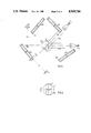
- FIGS. 5 and 6 illustrate a more complete goniometer.
- the etalon E of this embodiment is irradiated with two laser beams 51, 52, from respective lasers L1, L2.
- the beams define therebetween an angle of 45° and are displaced vertically through a distance d as shown in FIG. 6.
- the interference fringes in the two transmitted beams are caught on screens S1, S2 and are studied with fringe detectors D1 and D2.
- the goniometer also includes four reflection detectors 60-63, each of which has a screen, an objective and a light detector and which are placed in the plane of the beam 52.
- the angular distance between two mutually adjacent fringes is namely quite large at a 90° angle of incidence and varies considerably with said angle. Furthermore, if the fringes are to be visible, the two surfaces of the etalon E must be highly parallel with one another. Moreover, the fringes are bent. Consequently, these angles are to be avoided and the interval is split up between the two laser beams/detector arrays. Switching is effected by means of the detectors 60-63. In the FIG. 5 illustration the goniometer is assumed to have a setting of 0° (cf. FIG. 7) and that the laser beam 51 is detected with the aid of S1 and D1 at an angle of incidence of 45°.
- the laser beam 51 will be normal to the etalon when the table 50 is rotated through 45° in the positive sense (anti-clockwise). However, the beam 52 will impinge on the detector 61 prior to this, after rotating the table in the positive sense through 22.5°, wherewith detection is switched from the beam 51 to the beam 52. Similarly, rotation in the negative sense through 22.5° will result in reflection of the beam 52 onto the detector 62, for a corresponding switch. Correspondingly, at a positive angle of 67.5° the beam 52 will activate the detector 60, whereas at a negative angle of roughly 67.5° said beam 52 will be reflected onto the detector 63.
- FIG. 7 illustrates how the fringe spacing can be kept below 30" and shows the positions at which the switches are made.
Abstract
A plane-parallel plate (E) is irradiated with coherent light from a laser and an interference pattern observed on a screen (S) and imaged on a multi-channel, position defining detector (D). The interference pattern will move when the plate (E) is rotated about its axis. There is thus provided a highly sensitive angle-measuring device with which measurements can be made to fractions of a second of arc.
Description
The present invention relates to an optical device for measuring an angle between a beam of light and a measuring device.
The most common method of measuring angles is probably with the aid of a circular scale whose graduations are observed in one way or another. Automatic systems which operate on the basis of this principle are also to be found. Another principle is one which is based on reflecting light from a rotatable mirror onto a scale and observing the scale with the aid of a telescope and the mirror, this method being invented by Poggendorff in 1829. A third method is the auto-collimation method.
The present invention, however, relates to an interferometric method which approaches the principle of the so-called interference for equal inclinations named after Haidinger (1795-1871) and applied by Fabry and Perot in the interferometer named after these people and used for measuring wavelengths accurately. Although this method has certain complications, of which more will be said in the following, the theory which lies behind these known interferometers can be used to explain the present invention.
The theory of this interferometer has been relatively well developed over the past 80 years. An etalon comprising two partially reflecting and precisely parallel surfaces is irradiated on one side with the light to be studied and an optical system located on the other side enables the intensity of transmitted light to be studied in mutually different directions, this system in the simplest of cases comprising a positive lens and a screen positioned at the focal point of the lens. A number of interference rings will then appear on the screen, where the innermost ring corresponds to a wavelength which depending on the contribution afforded by the size of the ring, essentially coincides with the number of half wavelengths of the light making up the thickness of the etalon. The theory of the Fabry-Perot etalon is described, for instance, by Born & Wolf in "Principles of optics", 6th ed., 1980, chapters 7.5-7.6. and by Tolansky in, inter alia, "An introduction to interferometry".
In the case of such interferometric methods as these it is the innermost interference rings that are of interest. The invention instead preferably utilizes higher order interferences, which can be studied when the etalon is turned away from its conventional position in which the incident light is normal to the plane of the etalon. In contradistinction to the conventional Fabry-Perot interferences, the fringes which can then be observed are essentially vertical lines and with regard to terminology can be more precisely termed as Haidinger fringes or "fringes for equal inclination".
Interferometric measuring processes for measuring lengths or distances are known generally to the art. Reference can be made in this respect to, for instance, the Michelson interferometer and similar constructions which, due to the advent of the laser with its great coherence length, can be also used in practice to measure relatively long distances. Two Fabry-Perot etalons which are moved relative to one another in mutually parallel relationship have also been used to this end: cf. U.S. Pat. No. 4,558,950. The present invention, however relates to the use of a corresponding etalon as an angle detector, wherewith the Haidinger fringes which are obtained with rotation form a kind of natural "scale lines" moving past a detector. These "scale lines" define a monotonous but non-linear scale for defining the rotation of a plane-parallel plate in relation to a light cone projected from a laser device.
In the case of a standard Fabry-Perot interferometer, the space between the two partially reflecting surfaces is air, implying that each of the surfaces is carried by a respective slightly wedge-shaped glass plate. However, since the absolute value of the wavelength is of no interest in the case of the present invention, there is preferably used a plane-parallel glass plate, such plates being commercially available and used as interference filters. In certain cases very thick glass plates are also used e.g. plates having a thickness in the order of 100 mm, since the angular resolution is then very high. As will become apparent from the following description, precise parallelism is less important in the present case than in the case of a Fabry-Perot interferometer.
The principle under which fringes are produced is illustrated in FIG. 1. An incoming beam of light rays (only one ray has been shown), subsequent to refraction in the surface of the plate 1 (the index of refraction outside no being close to 1 in air, and the index of refraction in the plate being n') is repeatedly reflected or transmitted and gives rise to an outgoing beam of light rays which will amplify one another at certain angles θ, θ'. Elementary geometric conditions show that when the plate has a thickness h and the vacuum wavelength of the monochromatic light is λ0 the phase difference (in radians) between two successive light rays will be ##EQU1## or, as a function of the angle of incidence θ ##EQU2## Constructive interference is obtained when δ=m . 2π, where m is the order of interference (in integers). The angle θ is obtained from this relationship as a function of the order of interference in accordance with the expression ##EQU3##
The angle between two successive fringes
Δθ=θm-θm-1 (4)
can be obtained from the preceding expressions. The expression (3) shows that there is a non-linear but monotonous relationship between the angle θ and the order number m. The order number m has, naturally, a high value. For instance, when h=10 mm, λ0=632 nm and n'=1.5, the lowest value of m at which a fringe can be observed or discerned will lie in the region of 47,000.
A measure of the distance Δθ between mutually adjacent fringes can be obtained through derivation of the equation (3): ##EQU4##
With regard to θ, the derivative of this expression is (-1/sine θ).
It will readily be seen that the angle between two fringes will vary widely between near normal incidence, where said angle will be very large, and a grazing angle of incidence, where said angle will be much smaller. However, scale changes are relatively moderate in the case of angles which deviate from normal incidence. Furthermore, the interference fringes which lie close to normal incidence are bent and consequently have no useful purpose with regard to measurements In the case of representative embodiments of the invention, this may mean a jump in the detection of angles within the range, e.g. of -5°<θ<+5°. With an interference plate of 10 mm in thickness a typical interval of 30 arc seconds between 10° and 60° can be expected. The angular resolution that can be achieved depends on the detector used. If this detector has one or two components or elements the angular resolution will accordingly be of the same order of magnitude. A linear detector which has a high resolving power, can increase the resolution by a factor of 500, provided that there is sufficient visibility. This assumes, however, among other things, very narrow lines. The possibility of interpolation is poorer when a laser diode is used, although a resolution of 30 arc seconds can still be obtained with relative ease.
Visibility is contingent on the reflectiveness of the reflecting surfaces--the higher the reflectivity the narrower the fringes. With a reflectivity of 90% there is obtained 20°<θ<50°, and with a plate thickness of 12.7 mm a fringe width corresponding to 2 arc seconds.
The aforesaid drawback concerning poor observation possibilities at normal and near normal incidence can be overcome in accordance with one embodiment of the invention, by protecting two different laser beams onto the etalon, so that the beams will impinge thereon at mutually different angles. By arranging two lasers with a fixed angular laser-beam relationship of, e.g., 45° and providing for each laser a respective fringe detector for transmission and detectors in reflection for detecting direct reflection, such as accurate calibration detectors and like limit switches between the two beam paths, it is possible to maintain high resolution and to measure angles continuously from 0° to 360°.
The principle of the invention has been described with a starting point from conditions which relate to the theoretically well-known Fabry-Perot interferometer. The conditions which prevail in practice however are more complicated. Seen theoretically. Haidinger fringes are fringes at infinite distance, which can thus only be discerned when parallel beams have been focused to spots on a screen. In the case of the inventive arrangement however the observed fringes can be viewed directly on a screen and, by positioning the screen obliquely, the fringes can be made sharp but with increased mutual spacing therebetween. An advantage is therefore afforded when such a screen is positioned at an angle which corresponds to the grazing incidence (≈85°) of the outgoing beam and place an image thereof on a multi-channel or otherwise position-sensitive electric detector. Presumably, the reason why the fringes discerned when practising the invention do not lie at infinite distances, in accordance with the classic theory but can be captured on a screen at any distance, is because the light source used is a laser. Earlier theories namely rely on the supposition that light sources which are not punctiform must be considered to be composed of mutually incoherent, punctiform light sources. A laser, on the other hand, produces so-called non-localized interference fringes.
As beforementioned, a mutual fringe spacing or distance of 30 seconds of arc can be obtained with a plate thickness as small as 10 mm which with the aid of a position-sensitive detector is able to provide positive interpolation of the position to within 500-parts thereof, corresponding to six hundreths (6/100ths) of one second of arc. With regard to the fact that a good circular scale normally graduated with divisions equal to five (5) minutes of arc, will give an accidental measurement error of 0.2-0.5 seconds of arc but a systematic divisional error of 1-3 seconds of arc (Kohlrausch, "Praktische Physik", Stuttgart 1968, page 109) it is apparent that the invention makes possible a reproducible angular measurement which is at least one order of magnitude better than that obtained with the best known classical method, and that calibration to achieve the same accuracy as the reproducibility is a laborious task. Such accuracy is not always necessary, however, and the invention can also be applied for much lower degrees of precision. Thus, if the etalon is given a smaller thickness and the fringe distance consequently made larger, a simple measuring instrument can be used in cases of lower accuracies, therewith enabling the system to be readily automated.
Interpolation between fringes can also be obtained in the abscence of a position detecting detector, by instead rotating the etalon through small angles of known values. For example, the etalon can be caused to rotate at a constant speed of rotation while using a series of synchronous clock pulses in conjunction therewith, which pulses can be utilized for the purpose of interpolation.
Although the inventive device can be considered primarily as a goniometer, it is possible to apply the inventive principle to the construction of other kinds of instruments and measuring devices. For example, the invention can be applied in the construction of a contactless distance measuring device.
In the case of a first type of distance meter, a laser beam is caused to impinge on an object whose position in the direction of the beam is to be determined. The impinged spot emits radiation in different directions. The etalon is slightly offset in relation to the laser beam and the irradiated spot on the object is permitted to constitute the radiation source of the etalon, whereby the angle of radiation can be determined and, by "triangulation", therewith the desired distance.
In the case of a second type of distance measuring device there is used for measuring purposes a separate light beam whose direction of incidence is measured by rotating the etalon arranged in the laser beam until the measuring light beam, through reflection on the etalon, can be brought into coincidence with a fixed light detector, wherewith the rotational angle of the etalon is determined.
According to one particular embodiment of the invention, two angularly displaced etalons may be used therewith enabling an angular range of 0°-360° to be covered.
The invention will now be described with reference to nonlimiting exemplifying embodiments illustrated in the accompanying drawings.
FIG. 1, described above, illustrates the principle of the angle-dependent interferences on which the invention is based.
FIG. 2 is a schematic illustration of an angle measuring goniometer.
FIG. 3 illustrates a first distance measuring application.
FIG. 4 illustrates a second distance measuring application.
FIGS. 5 and 6 illustrate a further development of an angle measuring arrangement.
FIG. 7 illustrates how the spacing between fringes varies with the angle, with particular application on the example illustrated in FIGS. 5 and 6.
The principle according to which measurement is effected has been described in the aforegoing, with particular reference to FIG. 1. FIG. 2 illustrates highly schematically a goniometer which functions in accordance with the invention. A laser L emits a beam of coherent light which passes through a lens 2 and an aperture 3 and impinges on a rotatable etalon E, the angle of rotation of which is to be measured. A beam of light passing through the etalon E is caught on an obliquely positioned screen S. Produced on the screen are visually discernible interference fringes which can be imaged on a detector D, preferably a position sensitive detector, with the aid of a lens 4. Various kinds of suitable detectors are known to the art, e.g. diode arrays. As illustrated to one side of the detector D, an intensity distribution with peaks and troughs is obtained. The extent to which the fringes can be observed, corresponding to the sharpness of their intensity distribution, is contingent on the reflectivity of the etalon surfaces.
In the case of a tested etalon having a thickness of 12.7 mm and a reflectivity of 90%, the corresponding fringes had a width of ca 2" at incident angles of 20°-50°, and a mutually spacing of ca 30". By positioning the screen S obliquely, the 30" spacing can be broadened to about 3 mm prior to detection. Interference plates with thicknesses of 1-25 mm and diameters of 1-100 mm are preferred generally.
Low reflectivity makes it difficult to obtain fringes which are sufficiently rich in contrast, particularly at angles beneath about 30°. Consequently, in the case of transmission. reflectivities of 60-99.9% are preferred in general. However, fringes can also be studied in reflection, although at lower intensity, it being possible, however, to observe fringes at a much lower reflectivity (4%). Large angles of incidence produce poor intensity in the case of reflection when R=4%, and consequently it is generally preferred to work with transmission through the etalon. In the case of transmission, the fringe detector may be-stationarily mounted relative to the axis of the etalon, since the optical axis moves only some mm when the etalon is rotated.
FIG. 3 illustrates one application in the measurement of distances. A laser beam generated by the laser L is directed onto an object 6 whose position along the beam is to be determined. The object 6 will emit light from a small irradiated spot, this light impinging on the etalon E at an angle clearly defined by the position of the object. Similarly to manner described with reference to FIG. 2, interference fringes are caught on an inclined screen S, which is projected onto the position sensitive detector D. It will readily be seen that changes in the distance between the laser L and the object 6 can be measured, by observing the number of fringes which move past on the screen S. When considering the matter trigonometricalIy, it will also be seen that the decrease in the spacing between successive fringes with increasing angles of incidence is compensated for considerably by the fact that the change in angle over a given movement path in mm becomes progressively smaller the farther the object 6 is moved away from the laser, implying a compensating effect in a linearizing direction.
FIG. 4 illustrates a further application for defining distances, in which two lasers L and L' are used. In the case of the embodiment illustrated in FIG. 3 it is necessary, with regard to intensity that the object reflects a great deal of the irradiating laser beam. In the case of the FIG. 4 embodiment, however, the object is irradiated with a fixed laser L' and the etalon E is used as a mirror, to reflect light onto a detector D1, rotation of the etalon being effected through a servo-mechanism not shown. This rotation of the etalon E is measured with the aid of a laser beam produced by a further fixed laser L. which subsequent to transmission gives rise to fringes on the screen S. In this case, the combination of the laser L the etalon E and the screen S with the detector D functions purely as a goniometer, which produces a result similar to that produced by a conventional circular scale. The illustrated goniometer, however, is also particularly suitable for the automatic recording of data. For the purpose of obtaining a reference angle, the etalon E is suitably provided with a reference mark which can be observed with the aid of a detector D2 through a lens system 7. This system may instead be an auto-collimation system.
FIGS. 5 and 6 illustrate a more complete goniometer. The etalon E of this embodiment is irradiated with two laser beams 51, 52, from respective lasers L1, L2. The beams define therebetween an angle of 45° and are displaced vertically through a distance d as shown in FIG. 6. The interference fringes in the two transmitted beams are caught on screens S1, S2 and are studied with fringe detectors D1 and D2. The goniometer also includes four reflection detectors 60-63, each of which has a screen, an objective and a light detector and which are placed in the plane of the beam 52.
The angular distance between two mutually adjacent fringes is namely quite large at a 90° angle of incidence and varies considerably with said angle. Furthermore, if the fringes are to be visible, the two surfaces of the etalon E must be highly parallel with one another. Moreover, the fringes are bent. Consequently, these angles are to be avoided and the interval is split up between the two laser beams/detector arrays. Switching is effected by means of the detectors 60-63. In the FIG. 5 illustration the goniometer is assumed to have a setting of 0° (cf. FIG. 7) and that the laser beam 51 is detected with the aid of S1 and D1 at an angle of incidence of 45°. The laser beam 51 will be normal to the etalon when the table 50 is rotated through 45° in the positive sense (anti-clockwise). However, the beam 52 will impinge on the detector 61 prior to this, after rotating the table in the positive sense through 22.5°, wherewith detection is switched from the beam 51 to the beam 52. Similarly, rotation in the negative sense through 22.5° will result in reflection of the beam 52 onto the detector 62, for a corresponding switch. Correspondingly, at a positive angle of 67.5° the beam 52 will activate the detector 60, whereas at a negative angle of roughly 67.5° said beam 52 will be reflected onto the detector 63. Other detector configurations are, of course, conceivable, the main thing being that the switch from one beam to the other is made at angles which ensure that the near normal angles of incidence on the etalon E are avoided. FIG. 7 illustrates how the fringe spacing can be kept below 30" and shows the positions at which the switches are made.
This shows that the inventive principle can also be applied with a goniometer which rotates a full circle, despite the difficulties encountered with normal incidence (Strictly speaking the described signal sequence only covers angles of up to 180°, but, as will be understood, the detectors 60-63 enable measurements to be made over a full revolution and even over several revolutions.)
Because it is possible to use rapid detectors which can be evaluated in a known manner to determine the direction of the passage of the interference fringes, the purely mechanical difficulties concerning the journalling of the rotatable etalon can be overcome, so as to enable the angular resolution afforded by the interferometric method to be utilized in practice. Furthermore the angle of rotation can be measured to a far greater extent than was previously possible, both with regard to precision and to accuracy.
Claims (14)
1. Angle measuring arrangement for measuring an angle between a beam of electromagnetic radiation and a measuring device, wherein the beam is a coherent monochromatic beam, and wherein the measuring device includes a plane-parallel plate which comprises a medium transparent to the radiation and which is defined by two substantially parallel reflective surfaces, said measuring device further including a position sensitive interference fringe detector for detecting a plurality of multiple beam interference fringes generated in the plane-parallel plate by the coherent light beam.
2. An arrangement according to claim 1, wherein the plane-parallel plate and the position sensitive interference fringe detector are mutually mounted stationarily for measuring the angle of incidence of the light beam on the plane-parallel plate.
3. An arrangement according to claim 2, wherein the plane-parallel plate is made of glass or like material and is provided on mutually opposite sides with a reflective coating having a reflectivity within a range of 60-99.9%.
4. An arrangement according to claim 2, wherein the interference fringe detector includes a screen, which is inclined relative to a line normal to the detector which extends from the screen to the plate, an optical imaging element, and a position-sensitive detector which is located in the screen-imaging plane of said element.
5. An arrangement according to claim 1, wherein the apparatus includes a laser-beam emitting laser and the interference detector which are firmly joined together; and in that the plane-parallel plate is arranged for rotation about an axis which is parallel with the reflective surfaces of the plate and perpendicular to the laser beam.
6. An arrangement according to claim 5, wherein two laser beams are each arranged in respective planes which are mutually displaced in the direction of the rotational axis of the plate; in that interference fringe detectors are provided for detecting interference fringes generated by respective laser beams; and in that means are provided for detecting respective interference fringes within predetermined intervals under avoiding intervals at which respective laser beams impinge on the plate at near normal angle of incidence and at grazing angles of incidence.
7. An arrangement according to claim 6, wherein the interference fringe detector includes a screen, which is inclined relative to a line normal to the detector which extends from the screen to the plate, an optical imaging element, and a position-sensitive detector which is located in the screen-imaging plane of said element.
8. An arrangement according to claim 5, wherein the plane-parallel plate is made of glass or like material and is provided on mutually opposite sides with a reflective coating having a reflectivity within a range of 60-99.9%.
9. An arrangement according to claim 5, wherein the interference fringe detector includes a screen, which is inclined relative to a line normal to the detector which extends from the screen to the plate, an optical imaging element, and a position-sensitive detector which is located in the screen-imaging plane of said element.
10. An arrangement according to claim 1 wherein the plane-parallel plate is made of glass or like material and is provided on mutually opposite sides with a reflective coating having a reflectivity within a range of 60-99.9%.
11. An arrangement according to claim 10, wherein the interference fringe detector includes a screen, which is inclined relative to a line normal to the detector which extends from the screen to the plate, an optical imaging element, and a position-sensitive detector which is located in the screen-imaging plane of said element.
12. An arrangement according to claim 1, wherein the interference fringe detector includes a screen, which is inclined relative to a line normal to the detector which extends from the screen to the plate, an optical imaging element, and a position-sensitive detector which is located in the screen-imaging plane of said element.
13. An arrangement according to claim 1, wherein said coherent light beam is a laser beam arranged by means of a laser diode and a lens system is located in front of said diode.
14. An arrangement according to claim 1, further including a detector means for establishing a reference position for the rotatable pate.
Applications Claiming Priority (2)
| Application Number | Priority Date | Filing Date | Title |
|---|---|---|---|
| SE8702890-8 | 1987-07-16 | ||
| SE8702890A SE458153B (en) | 1987-07-16 | 1987-07-16 | OPTICAL ANGLE METHODON |
Publications (1)
| Publication Number | Publication Date |
|---|---|
| US4969744A true US4969744A (en) | 1990-11-13 |
Family
ID=20369141
Family Applications (1)
| Application Number | Title | Priority Date | Filing Date |
|---|---|---|---|
| US07/326,569 Expired - Fee Related US4969744A (en) | 1987-07-16 | 1988-06-30 | Optical angle-measuring device |
Country Status (5)
| Country | Link |
|---|---|
| US (1) | US4969744A (en) |
| EP (1) | EP0323998A1 (en) |
| JP (1) | JPH02500860A (en) |
| SE (1) | SE458153B (en) |
| WO (1) | WO1989000674A1 (en) |
Cited By (16)
| Publication number | Priority date | Publication date | Assignee | Title |
|---|---|---|---|---|
| US5287214A (en) * | 1991-04-12 | 1994-02-15 | Northern Telecom Limited | Fabry-Perot optical filters |
| WO2002035177A2 (en) * | 2000-05-03 | 2002-05-02 | Zygo Corporation | Dynamic angle measuring interferometer |
| US20030117631A1 (en) * | 2001-10-19 | 2003-06-26 | Hill Henry Allen | Interferometers for measuring changes in optical beam direction |
| US6674521B1 (en) | 2000-05-12 | 2004-01-06 | The Regents Of The University Of Michigan | Optical method and system for rapidly measuring relative angular alignment of flat surfaces |
| US20040109167A1 (en) * | 2002-10-31 | 2004-06-10 | Sandstrom Richard L. | Etalon testing system and process |
| US20070188417A1 (en) * | 2006-02-15 | 2007-08-16 | Hajjar Roger A | Servo-assisted scanning beam display systems using fluorescent screens |
| US20120050749A1 (en) * | 2010-08-24 | 2012-03-01 | Institute Of Optics And Electronics, Chinese Academy Of Sciences | Apparatus and method for detecting optical profile |
| US8292809B2 (en) | 2008-03-31 | 2012-10-23 | Nellcor Puritan Bennett Llc | Detecting chemical components from spectroscopic observations |
| DE102012205380A1 (en) * | 2012-04-02 | 2013-10-02 | Carl Zeiss Industrielle Messtechnik Gmbh | Method for measuring relative position of components of coordinate measuring device or machine tool, involves irradiating etalon with electromagnetic radiation and measuring transmitted portion of electromagnetic radiation |
| US8556430B2 (en) | 2007-06-27 | 2013-10-15 | Prysm, Inc. | Servo feedback control based on designated scanning servo beam in scanning beam display systems with light-emitting screens |
| WO2015048993A1 (en) | 2013-10-02 | 2015-04-09 | Carl Zeiss Industrielle Messtechnik Gmbh | Measuring the relative alignment and/or relative position of mutually movable components of a device, more particularly of a coordinate measuring machine |
| US20170138724A1 (en) * | 2014-06-27 | 2017-05-18 | Keba Ag | Apparatus for determining the angle between two planar workpiece surfaces |
| WO2017171042A1 (en) | 2016-03-31 | 2017-10-05 | 積水化学工業株式会社 | Polyvinyl acetal ionomer resin film, and laminated glass |
| WO2017171043A1 (en) | 2016-03-31 | 2017-10-05 | 積水化学工業株式会社 | Interlayer film for laminated glass, and laminated glass |
| US20190178637A1 (en) * | 2016-08-24 | 2019-06-13 | Keba Ag | Device for aligning an angle measuring instrument |
| DE112016001974B4 (en) | 2015-04-30 | 2023-05-17 | Tsinghua University | Method for measuring the angle of rotation using a Fabry-Pérot etalon |
Families Citing this family (5)
| Publication number | Priority date | Publication date | Assignee | Title |
|---|---|---|---|---|
| GB2266366B (en) * | 1992-04-16 | 1996-04-24 | Rank Taylor Hobson Ltd | Angle detection |
| DE102004014095B4 (en) * | 2004-03-13 | 2005-12-22 | Technische Universität Dresden | Laser goniometer e.g. for angle measurement, has laser to control equipment and energy source attached and detector unit and between laser and detector unit optical deflecting system is supported by plate |
| RU2599912C2 (en) * | 2014-01-30 | 2016-10-20 | Федеральное государственное бюджетное образовательное учреждение высшего профессионального образования Московский государственный университет геодезии и картографии (МИИГАиК) | Device for measuring change in angular coordinates of object in plane |
| CN111238409A (en) * | 2020-02-28 | 2020-06-05 | 中国科学院上海技术物理研究所 | Device and method for measuring large-angle optical wedge angle with high precision |
| CN111238408A (en) * | 2020-02-28 | 2020-06-05 | 中国科学院上海技术物理研究所 | Device and method for rapidly measuring parallelism of parallel flat plate |
Citations (2)
| Publication number | Priority date | Publication date | Assignee | Title |
|---|---|---|---|---|
| SU504080A1 (en) * | 1974-03-20 | 1976-02-25 | Предприятие П/Я Р-6324 | Interference sensor measuring angles of rotation of an object with a reflective surface |
| US4558950A (en) * | 1982-07-28 | 1985-12-17 | H. Maihak Ag | Interferometric distance and direction measurement |
Family Cites Families (2)
| Publication number | Priority date | Publication date | Assignee | Title |
|---|---|---|---|---|
| US3782826A (en) * | 1972-08-21 | 1974-01-01 | Cutler Hammer Inc | Method and apparatus for measuring rotational angles by measuring changes in optical beam path length |
| GB2044920B (en) * | 1979-01-27 | 1983-02-09 | Barr & Stroud Ltd | Optical interferometer |
-
1987
- 1987-07-16 SE SE8702890A patent/SE458153B/en not_active IP Right Cessation
-
1988
- 1988-06-30 JP JP63506025A patent/JPH02500860A/en active Pending
- 1988-06-30 EP EP88906202A patent/EP0323998A1/en not_active Ceased
- 1988-06-30 WO PCT/SE1988/000363 patent/WO1989000674A1/en not_active Application Discontinuation
- 1988-06-30 US US07/326,569 patent/US4969744A/en not_active Expired - Fee Related
Patent Citations (2)
| Publication number | Priority date | Publication date | Assignee | Title |
|---|---|---|---|---|
| SU504080A1 (en) * | 1974-03-20 | 1976-02-25 | Предприятие П/Я Р-6324 | Interference sensor measuring angles of rotation of an object with a reflective surface |
| US4558950A (en) * | 1982-07-28 | 1985-12-17 | H. Maihak Ag | Interferometric distance and direction measurement |
Cited By (28)
| Publication number | Priority date | Publication date | Assignee | Title |
|---|---|---|---|---|
| US5287214A (en) * | 1991-04-12 | 1994-02-15 | Northern Telecom Limited | Fabry-Perot optical filters |
| WO2002035177A2 (en) * | 2000-05-03 | 2002-05-02 | Zygo Corporation | Dynamic angle measuring interferometer |
| WO2002035177A3 (en) * | 2000-05-03 | 2002-10-03 | Zygo Corp | Dynamic angle measuring interferometer |
| US6563593B2 (en) | 2000-05-03 | 2003-05-13 | Zygo Corporation | Dynamic angle measuring interferometer |
| US6674521B1 (en) | 2000-05-12 | 2004-01-06 | The Regents Of The University Of Michigan | Optical method and system for rapidly measuring relative angular alignment of flat surfaces |
| US20030117631A1 (en) * | 2001-10-19 | 2003-06-26 | Hill Henry Allen | Interferometers for measuring changes in optical beam direction |
| US6917432B2 (en) | 2001-10-19 | 2005-07-12 | Zygo Corporation | Interferometers for measuring changes in optical beam direction |
| US20040109167A1 (en) * | 2002-10-31 | 2004-06-10 | Sandstrom Richard L. | Etalon testing system and process |
| US7136169B2 (en) * | 2002-10-31 | 2006-11-14 | Cymer, Inc. | Etalon testing system and process |
| US8451195B2 (en) * | 2006-02-15 | 2013-05-28 | Prysm, Inc. | Servo-assisted scanning beam display systems using fluorescent screens |
| US20070188417A1 (en) * | 2006-02-15 | 2007-08-16 | Hajjar Roger A | Servo-assisted scanning beam display systems using fluorescent screens |
| US8556430B2 (en) | 2007-06-27 | 2013-10-15 | Prysm, Inc. | Servo feedback control based on designated scanning servo beam in scanning beam display systems with light-emitting screens |
| US8814364B2 (en) | 2007-06-27 | 2014-08-26 | Prysm, Inc. | Servo feedback control based on designated scanning servo beam in scanning beam display systems with light-emitting screens |
| US9467668B2 (en) | 2007-06-27 | 2016-10-11 | Prysm, Inc. | Feedback control of display systems with light-emitting screens having excitation light source and phosphor layer |
| US8292809B2 (en) | 2008-03-31 | 2012-10-23 | Nellcor Puritan Bennett Llc | Detecting chemical components from spectroscopic observations |
| US20120050749A1 (en) * | 2010-08-24 | 2012-03-01 | Institute Of Optics And Electronics, Chinese Academy Of Sciences | Apparatus and method for detecting optical profile |
| US8842292B2 (en) * | 2010-08-24 | 2014-09-23 | Institute Of Optics And Electronics, Chinese Academy Of Sciences | Apparatus and method for detecting optical profile |
| DE102012205380A1 (en) * | 2012-04-02 | 2013-10-02 | Carl Zeiss Industrielle Messtechnik Gmbh | Method for measuring relative position of components of coordinate measuring device or machine tool, involves irradiating etalon with electromagnetic radiation and measuring transmitted portion of electromagnetic radiation |
| DE102012205380B4 (en) * | 2012-04-02 | 2014-09-25 | Carl Zeiss Industrielle Messtechnik Gmbh | Method and arrangement for measuring the relative orientation of mutually movable components of a device and sensor for a coordinate measuring machine |
| WO2015048993A1 (en) | 2013-10-02 | 2015-04-09 | Carl Zeiss Industrielle Messtechnik Gmbh | Measuring the relative alignment and/or relative position of mutually movable components of a device, more particularly of a coordinate measuring machine |
| US20170138724A1 (en) * | 2014-06-27 | 2017-05-18 | Keba Ag | Apparatus for determining the angle between two planar workpiece surfaces |
| US9733073B2 (en) * | 2014-06-27 | 2017-08-15 | Keba Ag | Apparatus for determining the angle between two planar workpiece surfaces |
| DE112016001974B4 (en) | 2015-04-30 | 2023-05-17 | Tsinghua University | Method for measuring the angle of rotation using a Fabry-Pérot etalon |
| WO2017171042A1 (en) | 2016-03-31 | 2017-10-05 | 積水化学工業株式会社 | Polyvinyl acetal ionomer resin film, and laminated glass |
| WO2017171043A1 (en) | 2016-03-31 | 2017-10-05 | 積水化学工業株式会社 | Interlayer film for laminated glass, and laminated glass |
| KR20180132637A (en) | 2016-03-31 | 2018-12-12 | 세키스이가가쿠 고교가부시키가이샤 | Interlayer and laminated glass for laminated glass |
| US11034137B2 (en) | 2016-03-31 | 2021-06-15 | Sekisui Chemical Co., Ltd. | Interlayer film for laminated glass, and laminated glass |
| US20190178637A1 (en) * | 2016-08-24 | 2019-06-13 | Keba Ag | Device for aligning an angle measuring instrument |
Also Published As
| Publication number | Publication date |
|---|---|
| EP0323998A1 (en) | 1989-07-19 |
| JPH02500860A (en) | 1990-03-22 |
| WO1989000674A1 (en) | 1989-01-26 |
| SE8702890L (en) | 1989-01-17 |
| SE458153B (en) | 1989-02-27 |
| SE8702890D0 (en) | 1987-07-16 |
Similar Documents
| Publication | Publication Date | Title |
|---|---|---|
| US4969744A (en) | Optical angle-measuring device | |
| JPS6021783Y2 (en) | Light wavelength measuring device | |
| US4897536A (en) | Optical axis displacement sensor with cylindrical lens means | |
| US4131365A (en) | Method and apparatus for determining object position and dimension using a diffraction wave | |
| JPH073344B2 (en) | Encoder | |
| US4025197A (en) | Novel technique for spot position measurement | |
| US3554646A (en) | Optical distance gage | |
| US4009965A (en) | Method and apparatus for determining object dimension and other characteristics using diffraction waves | |
| JPH0652170B2 (en) | Optical imaging type non-contact position measuring device | |
| CA1323434C (en) | Apparatus for measuring the thickness of a thin film | |
| US4113388A (en) | Optical apparatus for determining relative positioning of two members | |
| US4395123A (en) | Interferometric angle monitor | |
| CN110082071B (en) | Device and method for measuring optical parallel difference of right-angle prism | |
| US5995215A (en) | Autocollimator with grating | |
| JPS6288905A (en) | Noncontact diameter measuring method and device for thin wire rod, etc. | |
| US5448355A (en) | System for measuring tilt of image plane of optical system using diffracted light | |
| US5724130A (en) | Technique for the measurement and calibration of angular position | |
| US4451148A (en) | Optical angular interval marker | |
| JP3461566B2 (en) | Interferometer for measuring cone shape | |
| RU2502951C1 (en) | Nano- and sub-nanometer accuracy apparatus for controlling position of object | |
| JPS6041287B2 (en) | Small angle measurement method | |
| RU2044271C1 (en) | Device for checking small angular rotations | |
| JPS62200223A (en) | Encoder | |
| JP3517506B2 (en) | Optical displacement measuring device | |
| JPH0464566B2 (en) |
Legal Events
| Date | Code | Title | Description |
|---|---|---|---|
| AS | Assignment |
Owner name: POLYMETRIC AB, SWEDEN Free format text: ASSIGNMENT OF ASSIGNORS INTEREST.;ASSIGNOR:ORDELL, ERIK;REEL/FRAME:005038/0356 Effective date: 19890126 |
|
| FEPP | Fee payment procedure |
Free format text: PAYOR NUMBER ASSIGNED (ORIGINAL EVENT CODE: ASPN); ENTITY STATUS OF PATENT OWNER: SMALL ENTITY |
|
| REMI | Maintenance fee reminder mailed | ||
| LAPS | Lapse for failure to pay maintenance fees | ||
| FP | Lapsed due to failure to pay maintenance fee |
Effective date: 19941116 |
|
| STCH | Information on status: patent discontinuation |
Free format text: PATENT EXPIRED DUE TO NONPAYMENT OF MAINTENANCE FEES UNDER 37 CFR 1.362 |