US4969010A - Copying machine - Google Patents
Copying machine Download PDFInfo
- Publication number
- US4969010A US4969010A US07/274,451 US27445188A US4969010A US 4969010 A US4969010 A US 4969010A US 27445188 A US27445188 A US 27445188A US 4969010 A US4969010 A US 4969010A
- Authority
- US
- United States
- Prior art keywords
- upper body
- hinge
- copying machine
- rod
- lower body
- Prior art date
- Legal status (The legal status is an assumption and is not a legal conclusion. Google has not performed a legal analysis and makes no representation as to the accuracy of the status listed.)
- Expired - Fee Related
Links
- 230000007246 mechanism Effects 0.000 claims abstract description 23
- 230000002787 reinforcement Effects 0.000 claims description 17
- 230000008878 coupling Effects 0.000 claims 6
- 238000010168 coupling process Methods 0.000 claims 6
- 238000005859 coupling reaction Methods 0.000 claims 6
- 230000006835 compression Effects 0.000 description 13
- 238000007906 compression Methods 0.000 description 13
- 238000012423 maintenance Methods 0.000 description 6
- 230000008439 repair process Effects 0.000 description 6
- 108091008695 photoreceptors Proteins 0.000 description 5
- 239000002184 metal Substances 0.000 description 3
- 230000003287 optical effect Effects 0.000 description 3
- 230000009471 action Effects 0.000 description 2
- 238000004140 cleaning Methods 0.000 description 2
- 230000000694 effects Effects 0.000 description 2
- 238000000605 extraction Methods 0.000 description 2
- 238000003780 insertion Methods 0.000 description 2
- 230000037431 insertion Effects 0.000 description 2
- 230000009467 reduction Effects 0.000 description 2
- 229920003002 synthetic resin Polymers 0.000 description 2
- 239000000057 synthetic resin Substances 0.000 description 2
- 238000007599 discharging Methods 0.000 description 1
- 238000009434 installation Methods 0.000 description 1
- 230000000007 visual effect Effects 0.000 description 1
Images


Classifications
-
- G—PHYSICS
- G03—PHOTOGRAPHY; CINEMATOGRAPHY; ANALOGOUS TECHNIQUES USING WAVES OTHER THAN OPTICAL WAVES; ELECTROGRAPHY; HOLOGRAPHY
- G03G—ELECTROGRAPHY; ELECTROPHOTOGRAPHY; MAGNETOGRAPHY
- G03G21/00—Arrangements not provided for by groups G03G13/00 - G03G19/00, e.g. cleaning, elimination of residual charge
- G03G21/16—Mechanical means for facilitating the maintenance of the apparatus, e.g. modular arrangements
- G03G21/1604—Arrangement or disposition of the entire apparatus
- G03G21/1623—Means to access the interior of the apparatus
- G03G21/1633—Means to access the interior of the apparatus using doors or covers
-
- G—PHYSICS
- G03—PHOTOGRAPHY; CINEMATOGRAPHY; ANALOGOUS TECHNIQUES USING WAVES OTHER THAN OPTICAL WAVES; ELECTROGRAPHY; HOLOGRAPHY
- G03G—ELECTROGRAPHY; ELECTROPHOTOGRAPHY; MAGNETOGRAPHY
- G03G21/00—Arrangements not provided for by groups G03G13/00 - G03G19/00, e.g. cleaning, elimination of residual charge
- G03G21/16—Mechanical means for facilitating the maintenance of the apparatus, e.g. modular arrangements
- G03G21/1604—Arrangement or disposition of the entire apparatus
- G03G21/1623—Means to access the interior of the apparatus
- G03G21/1628—Clamshell type
-
- G—PHYSICS
- G03—PHOTOGRAPHY; CINEMATOGRAPHY; ANALOGOUS TECHNIQUES USING WAVES OTHER THAN OPTICAL WAVES; ELECTROGRAPHY; HOLOGRAPHY
- G03G—ELECTROGRAPHY; ELECTROPHOTOGRAPHY; MAGNETOGRAPHY
- G03G2221/00—Processes not provided for by group G03G2215/00, e.g. cleaning or residual charge elimination
- G03G2221/16—Mechanical means for facilitating the maintenance of the apparatus, e.g. modular arrangements and complete machine concepts
- G03G2221/1651—Mechanical means for facilitating the maintenance of the apparatus, e.g. modular arrangements and complete machine concepts for connecting the different parts
- G03G2221/1654—Locks and means for positioning or alignment
-
- G—PHYSICS
- G03—PHOTOGRAPHY; CINEMATOGRAPHY; ANALOGOUS TECHNIQUES USING WAVES OTHER THAN OPTICAL WAVES; ELECTROGRAPHY; HOLOGRAPHY
- G03G—ELECTROGRAPHY; ELECTROPHOTOGRAPHY; MAGNETOGRAPHY
- G03G2221/00—Processes not provided for by group G03G2215/00, e.g. cleaning or residual charge elimination
- G03G2221/16—Mechanical means for facilitating the maintenance of the apparatus, e.g. modular arrangements and complete machine concepts
- G03G2221/1678—Frame structures
- G03G2221/1687—Frame structures using opening shell type machines, e.g. pivoting assemblies
Definitions
- the invention relates to a copying machine comprising upper and lower bodies which are bound by a hinge on one side, and the upper body is designed to open at a predetermined angle.
- a copying machine comprises, in general, upper and lower bodies which can be opened by a hinge with a paper passage from a paper feeding part to a paper discharging part as its boundary and designed to facilitate the removal of jamming caused by a recording sheet and the maintenance, adjustment, and repair of the machine.
- the upper and lower bodies of such type copying machine are bound by a hinge on one side, and the upper body is forced by a spring in order to open at a predetermined angle.
- a conventional spring forcing means has been a torsion bar type or a pneumatic spring type so that the spring always works at the time of opening the upper body. Therefore, at the time of maintenance, adjustment, and repair of the machine, unless otherwise the spring force is completely released, there have been difficulties in removal of the upper body from the lower body and its reassembly, causing low efficiency of the operation.
- This invention is designed to solve said problems and to provide a new type copying machine, in which a spring securely works at the time of opening and closing the upper body and the spring can be easily released at the time of removal of the upper body from the lower body and its reassembly in order to carry out the maintenance, adjustment, and repair of the machine.
- this invention provides a new type copying machine comprising upper and lower bodies which are bound by a hinge on one side and a counter balance mechanism near the hinge binding part which works at the time of opening and closing the upper body within a predetermined angle and stops functioning at the time of opening the upper body beyond the predetermined angle.
- An object of this invention is to provide a lightweight type copying machine with sufficient strength; therefore, main members on which the moment load is imposed are manufactured of metal having sufficient strength, and other parts of the structure, synthetic resin molds.
- Another object of this invention is to provide a simple device which can securely lock the upper and lower bodies together.
- the present invention specifically relates to a copying machine, which comprises:
- a counterbalance mechanism installed in the vicinity of the hinge which works at the time of opening and closing the upper body within a predetermined angle, and stops functioning at the time of opening the upper body when it opens beyond the predetermined angle.
- FIG. 1 is a schematic front elevation in section at the time of closing the upper body.
- FIG. 2 is an exploded perspective view showing reinforcement of the lower body and the hinge binding part.
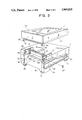
- FIG. 3 is a front sectional view at the time of opening the upper body.
- FIG. 4(a),(b) and (c) are explanatory drawings showing functions of the counterbalance mechanism.
- FIG. 5 is a visual fragmentary perspective view showing the lock mechanism.
- FIG. 6(a) and (b) are section views showing functions of the hook.
- the copying machine of the present invention has hinged upper body 1 and lower body 2, and a counterbalance mechanism 37 located between the upper body 1 and the lower body 2 which functions within a predetermined angle of use of the hinge 3, and the counterbalance mechanism 37 comprises,
- FIGS. shown by 1 is an upper body and 2, a lower body. These upper and lower bodies 1, 2 are bound by means of a hinge binding part 3 so as to open. A platen 1a is fitted on top of the upper body 1, and an original cover 1b is mounted movably on the platen in order to press against it.
- Shown by 4 is an optical system comprising a light source 4a' which can move while applying light to an original copy on the platen 1a, a first mirror 4b fixed to the light source unit 4a, a second and third mirrors 4c and 4d deflecting the reflection light from the first mirror, a variable power lens 4e and a fourth mirror 45.
- Shown by 5 is a developing unit disposing a photoreceptor drum 6 in the center of a casing 5a, and a charging part 7, a developing part 8, a drum exposure part 9' corresponding to a transfer part 9, and a cleaning part 10 in the casing.
- the developing unit 5, movable toward the front side (an operator side), is suspended from rails 12a, 12b installed beneath a bottom plate 11 (a bottom plate of the optical system) of the upper body 1 by means of projections 5b, 5c provided on both sides of the casing 5a.
- the transfer part 9 is installed in the lower body 2 as opposed to the photoreceptor drum 6 via a paper passage 13 formed between them.
- Shown by 14 is a storage cassette storing stacked copy sheets, drawable from the front side, which is installed in a space 2a under the lower body 2.
- Shown by 15 is a paper feeding unit comprising a semicircular roller 16 which forwards copy sheet one at a time from the cassette 14 to the paper passage 13, a paper feeding roller 18 which timely feeds paper between the photoreceptor drum 6 and the transfer part 9, and a manual paper feed tray 19, capable of insertion and extraction, on the outer surface of a side wall of the lower body 2.
- a manual paper feed tray passage 20 connecting to the manual paper feed tray 19 is equipped with a manual paper feed roller 21.
- Shown by 22 is a fixing unit which fixes a toner picture by applying heat and pressure on the copy sheet after being transferred in the transfer part 9.
- This fixing unit 22 is equipped with a fixing roller 24a, a press roller 24b, and a cleaning roller 25 on a frame body 23 fixed on the lower body 2, as well as paper discharge rollers 26a and 26b.
- the paper discharged from these discharge roller 26a, 26b is stacked on a paper discharge tray 28, capable of insertion and extraction, fixed to the outer wall, extendedly from an inner bottom 27 of the other side of the lower body 2.
- the foregoing hinge binding part 3 is, as shown in FIG. 2, provided with a hole 31 on a projecting part 30 provided extendedly from a side edge of each of front and rear frames 29, 29' of the upper body 1 and a hinge shaft 34 horizontally and identically implanted on both sides of a box-shape member 33 installed between front and rear frames 32, 32' of the lower body 2, by which these hole and hinge shaft are connected, and a C ring 34" is fitted in an annular groove 34' provided a point of the hinge shaft 34. Therefore, the upper body 1 is easily removed and reassembled only by being moved toward one direction along the hinge shaft after the removal of the C ring.
- FIG. 5 shown by 55 is the lock means which keeps free end sides of the upper and lower bodies 1, 2 in closed condition.
- This lock means 55 can swing about the central shaft 21' of said manual paper feed roller 21.
- the hook (engaging part) 55 having an inclined surface 55' on the top surface is provided on the top end of right and left sides of the outer member 54, respectively, which furnishes a paper feed port 21" in its center.
- This hook 55 is designed to be engaged with an end part (engaged part) 56 of the bottom 11 of the upper body 1.
- the upper surface of the foregoing rail 12a of the developing unit is utilized for this engaged part 56.
- the outer member 54 is, as shown in FIG. 5, engaged counterclockwise (a direction to actualize the engagement of the hook 55) by functions of the helical compression springs 57a, 57b, respectively mounted between the right and left side lower surfaces of this outer member and the lower body 2. Therefore, when an operator tries to close and lock the upper body 1, he may just press down the top surface of the upper body 1 (by hand). Then, the lower edge part of the rail 12a hits on the inclined top surface 55' of the hook 55, making the outer member 54 swing clockwise by resisting functions of the helical compression springs 57a and 57b, resulting in the engagement of the lower surface of the hook 55 with the top surface of the rail 12a.
- a printed seal 60 (for example, a seal with printed pictures or letters such as "Press Here!) may be affixed to the position equivalent to the arrow a, or the helical compression spring on the far side of the machine (either 57a or 57b) may be tightened or the spring on the operator side may be omitted. Even so, a simultaneous engagement effect can be obtained.
- the concave groove 58 is provided as shown in FIG. 6(a), and convex part 55" on the lower surface of the hook 55 can be fitted into this groove.
- FIG. 2 Shown by 37 is a counterbalance mechanism provided near the hinge binding part 3, which forces the upper body 1 to an open direction. As shown in FIG. 3, this counterbalance mechanism 37 causes the upper body 1 to open at a predetermined angle (approximately 30°), and it does not function beyond this angle.
- the counterbalance mechanism 37 is, as shown in FIG. 4(a), comprised of a rod 39 mounted on a spherical part 39a provided on the basic end of a lower surface board 38 of the box-shape member 33 and installed between the front and rear frames 32, 32' of the lower body 2, and a helical compression spring 40 fitted on the rod 39.
- this helical compression spring 40 is controlled by a washer 42 engaged in a spherical body (an upper end large diameter part) 41 fixed on the top end of the rod 39. That is, when the upper body 1 is closed as shown in FIG. 1, the upper end spherical body 41 fixed on the rod 39 passes through a hole 44 provided on a corresponding part of a reinforcement frame 43 installed between the projecting parts 30 and 30' comprising said hinge binding part 3, and the washer 42 keeps the helical compression spring 40 in the compressed condition directly touching the reinforcement frame 43. Therefore, when the lock means 55 is released, the helical compression spring 40 pushes the reinforcement frame 43 up through the washer 42 by its resilient action, and then, as shown in FIG.
- the upper body 1 opens about the hinge binding part 3 as the axle.
- the maximum extensible volume of the helical compression spring 40 is controlled by the washer 42 engaged in the upper end spherical body 41 on the rod 39, and the spring 40 maintains the upper body 1 in the open condition at the predetermined angle, as shown in FIG. 4(b).
- the counterbalance mechanism only functions between its closed position shown in FIG. 4(a) and its open position shown in FIG. 4(b).
- the top end of the helical compression spring 40 cannot follow the movement of this upper body, and the spring action has no effect on the upper body. Therefore, in this condition, removal and reassembly of the upper body can be easily carried out by moving the upper body toward one direction from the lower body along the hinge shaft 34.
- Said helical compression spring 40 is curved toward the hinge binding part 3, which results from the incurved rod 39. Since the helical compression spring is curved in such a way, the direction of the spring corresponds to a circular arc of the upper body 1 at the time of its opening about the hinge binding part 3 as the axle, leading to high efficiency of the spring. Since the helical compression spring 40 raises the upper body and the developing unit attached thereto, within the vicinity of the hinge binding part 3, sufficient resilience is required of this spring; but extraordinary resilience such as to pop open the upper body at the time of release of the lock means is not necessary.
- the light source 4a in the optical system 4 moves, and the original information is changed into latent images on the photoreceptor drum 6; then, they are developed into toner pictures in the developing part.
- the toner pictures are transferred on the copy sheet sent out from the cassette through the semicircular 16 and paper feeding rollers 18 and fixed in the fixing part. Finally the copy sheet having a copied image is discharged to the paper discharge tray.
- the lock means 55 When the sheet is jamming in the passage on the way from the cassette to the discharge part, the lock means 55 is rotated to release the hook 55' from the rail 12a of the upper body 1, whereby the upper body 1 is opened in a clamshell form about the hinge binding part 3, which serves as the axle, by the function of the counter balance mechanism 37.
- the developing unit 5 since the developing unit 5 is also raised along with the upper body 1, the paper passage 13 located between the photoreceptor drum 6 and the transfer part 9 remaining on the lower body is completely exposed as shown in FIG. 3.
- the removal operation (as well as the reassembly) can be easily carried out if the upper body 1 is raised beyond the predetermined angle, in which the counterbalance mechanism fails to function.
- reinforcement members 32 and 32' are integrated in the lower body.
- the reinforcement members 32, 32', perpendicular to the hinge shaft 34 of the hinge binding part 3, are formed by metal deformed channel-type members and installed in the front and rear walls of the lower body, respectively.
- the reinforcement member 32' in the rear wall is fixed directly against the bottom of the lower body 2, and the reinforcement member 32 in the front wall is installed between supports 50 and 51 striding across a cassette inserting part 2a.
- Shown by 52 is a leg member mounted beneath the lower body 2, corresponding to both edges of said reinforcement members 32, 32'. That is, at the time of closing the upper body, loads, including a moment load, falling on the reinforcement members 32, 32' are concentrated on the leg member 52.
- the clamshell-type copying machine in which the upper and lower bodies are hinged on one side, is characterized by the installation of the counterbalance mechanism provided near the hinge binding part which functions well when the upper body is opened and closed within the predetermined angle though fails to work beyond said predetermined angle.
- the spring works well.
- the spring functions can be easily released which, owing to this invention, results in easy, safe work and extremely improved work efficiency.
- the copying machine in which the upper and lower bodies are hinged on one side and the counterbalance mechanism is provided near the hinge binding part, making the upper body open, is characterized by the reinforcement members, perpendicular to the hinge shaft of said hinge binding part, and the leg members provided under the lower body corresponding to both end parts of said reinforcement members. Therefore, most of the moment loads, caused by resiliency against the forcing power of the counterbalance mechanism toward the open direction and of the fixing unit toward the press direction, are concentrated on the leg members through the reinforcement members made from metal.
- the body main body structure is formed by synthetic resin molds in order to lighten the weight and maintain sufficient strength of the machine.
- the copying machine in which the upper and lower bodies are hinged on one side and the upper body is forced by the spring toward the open direction, is characterized by the engagement of the outer member of the lower body with the upper body.
Abstract
Description
Claims (12)
Applications Claiming Priority (6)
| Application Number | Priority Date | Filing Date | Title |
|---|---|---|---|
| JP62-298810 | 1987-11-26 | ||
| JP62298810A JPH01140169A (en) | 1987-11-26 | 1987-11-26 | Bisecting type copying device |
| JP62317693A JPH01158462A (en) | 1987-12-16 | 1987-12-16 | Separable copying device into two parts |
| JP62-317693 | 1987-12-16 | ||
| JP62-319901 | 1987-12-17 | ||
| JP62319901A JPH01161263A (en) | 1987-12-17 | 1987-12-17 | Separable copying device |
Publications (1)
| Publication Number | Publication Date |
|---|---|
| US4969010A true US4969010A (en) | 1990-11-06 |
Family
ID=27338251
Family Applications (1)
| Application Number | Title | Priority Date | Filing Date |
|---|---|---|---|
| US07/274,451 Expired - Fee Related US4969010A (en) | 1987-11-26 | 1988-11-21 | Copying machine |
Country Status (1)
| Country | Link |
|---|---|
| US (1) | US4969010A (en) |
Cited By (20)
| Publication number | Priority date | Publication date | Assignee | Title |
|---|---|---|---|---|
| US5066976A (en) * | 1990-03-19 | 1991-11-19 | Fuji Xerox Co., Ltd. | Image forming apparatus having a print cartridge |
| EP0501497A2 (en) * | 1991-03-01 | 1992-09-02 | Canon Kabushiki Kaisha | Image forming system and process cartridge removably mountable on same |
| US5162846A (en) * | 1992-01-02 | 1992-11-10 | Eastman Kodak Company | Cover control mechanism |
| EP0565094A2 (en) * | 1992-04-08 | 1993-10-13 | Konica Corporation | Image forming apparatus of a clamshell type |
| US5331374A (en) * | 1992-07-13 | 1994-07-19 | Mita Industrial Co., Ltd. | Image forming apparatus capable of opening a main body on one side |
| US5345257A (en) * | 1991-03-08 | 1994-09-06 | Mita Industrial Co., Ltd. | Box body construction of a digital image forming apparatus |
| US5355195A (en) * | 1992-04-07 | 1994-10-11 | Mita Industrial Co., Ltd. | Copying machine |
| US5400119A (en) * | 1991-04-30 | 1995-03-21 | Mita Industrial Co., Ltd. | Image forming apparatus |
| US5438390A (en) * | 1991-03-12 | 1995-08-01 | Mita Industrial Co., Ltd. | Image forming apparatus having monocoque housing structure including unitary toner collecting vessel |
| US5485244A (en) * | 1992-08-03 | 1996-01-16 | Star Micronics Co., Ltd. | Electrophotographic apparatus with freely openable upper and lower housings |
| GB2297721A (en) * | 1994-09-30 | 1996-08-14 | Ricoh Kk | Cartridge for image forming apparatus |
| US5565961A (en) * | 1992-12-14 | 1996-10-15 | Canon Kabushiki Kaisha | Process cartridge and image forming apparatus adapted for the mounting of the same thereto with an elastic member disposed therebetween |
| US5606408A (en) * | 1994-09-30 | 1997-02-25 | Ricoh Company, Ltd. | Image forming apparatus and cleaning device therefor |
| US5737667A (en) * | 1994-01-28 | 1998-04-07 | Canon Kabushiki Kaisha | Image forming apparatus having a gripper portion |
| US5905926A (en) * | 1996-11-15 | 1999-05-18 | Mita Industrial Co., Ltd. | Positioning structure for brake force supplier for use in image forming apparatus |
| US20030206224A1 (en) * | 2002-05-02 | 2003-11-06 | Brother Kogyo Kabushiki Kaisha | Image forming device including mechanism to lock cover |
| WO2008144064A1 (en) * | 2007-05-21 | 2008-11-27 | Judith Bender | Children's copying machine |
| CN100461011C (en) * | 2003-08-08 | 2009-02-11 | 佳能株式会社 | Image forming apparatus |
| US20130164025A1 (en) * | 2011-12-26 | 2013-06-27 | Shogo Mori | Image Forming Apparatus |
| US11022930B2 (en) | 2017-12-25 | 2021-06-01 | Kyocera Document Solutions Inc. | Mounting base and image forming apparatus set |
Citations (3)
| Publication number | Priority date | Publication date | Assignee | Title |
|---|---|---|---|---|
| US4124296A (en) * | 1976-09-01 | 1978-11-07 | Canon Kabushiki Kaisha | Original urging device |
| US4609276A (en) * | 1981-08-07 | 1986-09-02 | Canon Kabushiki Kaisha | Image formation apparatus |
| US4641947A (en) * | 1982-08-20 | 1987-02-10 | Tokyo Shibaura Denki Kabushiki Kaisha | Housing apparatus |
-
1988
- 1988-11-21 US US07/274,451 patent/US4969010A/en not_active Expired - Fee Related
Patent Citations (3)
| Publication number | Priority date | Publication date | Assignee | Title |
|---|---|---|---|---|
| US4124296A (en) * | 1976-09-01 | 1978-11-07 | Canon Kabushiki Kaisha | Original urging device |
| US4609276A (en) * | 1981-08-07 | 1986-09-02 | Canon Kabushiki Kaisha | Image formation apparatus |
| US4641947A (en) * | 1982-08-20 | 1987-02-10 | Tokyo Shibaura Denki Kabushiki Kaisha | Housing apparatus |
Cited By (29)
| Publication number | Priority date | Publication date | Assignee | Title |
|---|---|---|---|---|
| US5066976A (en) * | 1990-03-19 | 1991-11-19 | Fuji Xerox Co., Ltd. | Image forming apparatus having a print cartridge |
| US5258811A (en) * | 1991-03-01 | 1993-11-02 | Canon Kabushiki Kaisha | Image forming system and process cartridge removably mountable on same |
| EP0501497A2 (en) * | 1991-03-01 | 1992-09-02 | Canon Kabushiki Kaisha | Image forming system and process cartridge removably mountable on same |
| EP0501497A3 (en) * | 1991-03-01 | 1993-06-02 | Canon Kabushiki Kaisha | Image forming system and process cartridge removably mountable on same |
| US5345257A (en) * | 1991-03-08 | 1994-09-06 | Mita Industrial Co., Ltd. | Box body construction of a digital image forming apparatus |
| US5438390A (en) * | 1991-03-12 | 1995-08-01 | Mita Industrial Co., Ltd. | Image forming apparatus having monocoque housing structure including unitary toner collecting vessel |
| US5400119A (en) * | 1991-04-30 | 1995-03-21 | Mita Industrial Co., Ltd. | Image forming apparatus |
| US5162846A (en) * | 1992-01-02 | 1992-11-10 | Eastman Kodak Company | Cover control mechanism |
| US5355195A (en) * | 1992-04-07 | 1994-10-11 | Mita Industrial Co., Ltd. | Copying machine |
| EP0565094A3 (en) * | 1992-04-08 | 1994-08-24 | Konishiroku Photo Ind | Image forming apparatus of a clamshell type |
| EP0565094A2 (en) * | 1992-04-08 | 1993-10-13 | Konica Corporation | Image forming apparatus of a clamshell type |
| US5382998A (en) * | 1992-04-08 | 1995-01-17 | Konica Corporation | Image forming apparatus of a clamshell type |
| US5331374A (en) * | 1992-07-13 | 1994-07-19 | Mita Industrial Co., Ltd. | Image forming apparatus capable of opening a main body on one side |
| US5485244A (en) * | 1992-08-03 | 1996-01-16 | Star Micronics Co., Ltd. | Electrophotographic apparatus with freely openable upper and lower housings |
| US5565961A (en) * | 1992-12-14 | 1996-10-15 | Canon Kabushiki Kaisha | Process cartridge and image forming apparatus adapted for the mounting of the same thereto with an elastic member disposed therebetween |
| US5737667A (en) * | 1994-01-28 | 1998-04-07 | Canon Kabushiki Kaisha | Image forming apparatus having a gripper portion |
| GB2297721A (en) * | 1994-09-30 | 1996-08-14 | Ricoh Kk | Cartridge for image forming apparatus |
| US5606408A (en) * | 1994-09-30 | 1997-02-25 | Ricoh Company, Ltd. | Image forming apparatus and cleaning device therefor |
| GB2297721B (en) * | 1994-09-30 | 1996-12-04 | Ricoh Kk | A single process unit for use in an image forming process |
| US5905926A (en) * | 1996-11-15 | 1999-05-18 | Mita Industrial Co., Ltd. | Positioning structure for brake force supplier for use in image forming apparatus |
| US20030206224A1 (en) * | 2002-05-02 | 2003-11-06 | Brother Kogyo Kabushiki Kaisha | Image forming device including mechanism to lock cover |
| US6851802B2 (en) * | 2002-05-02 | 2005-02-08 | Brother Kogyo Kabushiki Kaisha | Image forming device including mechanism to lock cover |
| US20050110818A1 (en) * | 2002-05-02 | 2005-05-26 | Brother Kogyo Kabushiki Kaisha | Image forming device including mechanism to lock cover |
| US7384042B2 (en) | 2002-05-02 | 2008-06-10 | Brother Kogyo Kabushiki Kaisha | Image forming device including mechanism to lock cover |
| CN100461011C (en) * | 2003-08-08 | 2009-02-11 | 佳能株式会社 | Image forming apparatus |
| WO2008144064A1 (en) * | 2007-05-21 | 2008-11-27 | Judith Bender | Children's copying machine |
| US20130164025A1 (en) * | 2011-12-26 | 2013-06-27 | Shogo Mori | Image Forming Apparatus |
| US8953978B2 (en) * | 2011-12-26 | 2015-02-10 | Brother Kogyo Kabushiki Kaisha | Image forming apparatus |
| US11022930B2 (en) | 2017-12-25 | 2021-06-01 | Kyocera Document Solutions Inc. | Mounting base and image forming apparatus set |
Similar Documents
| Publication | Publication Date | Title |
|---|---|---|
| US4969010A (en) | Copying machine | |
| US5041872A (en) | Image forming apparatus using a photosensitive drum selectively pivoting with an upper part of the housing | |
| US8103186B2 (en) | Image forming apparatus | |
| KR101191091B1 (en) | Hinge with tandem pivot structure motion lock and override | |
| EP0448051B1 (en) | Rolled-paper feed unit for an image forming apparatus | |
| US5794103A (en) | Developer unit mounting/detaching device in a laser beam printer for replacement of developer unit without opening and closing a cover | |
| US4705384A (en) | Image forming apparatus with locking means | |
| US6615019B2 (en) | Automatic original feeding apparatus and image forming apparatus provided with the same | |
| US5206681A (en) | Arrangement for facilitating opening and closing a clamshell type of copying machine | |
| US4542976A (en) | Partially openable image forming apparatus | |
| US7869738B2 (en) | Image forming apparatus | |
| JPS5913247A (en) | Image forming device | |
| JPH1184983A (en) | Electrophotographic image forming device | |
| EP0383983A1 (en) | Image forming apparatus | |
| US4432639A (en) | Reciprocative original carrier locking mechanism | |
| JP3198142B2 (en) | Image forming device | |
| US5418601A (en) | Clamshell-type image forming apparatus having engaging hook and sliding lock member | |
| JPH05323686A (en) | Image forming device | |
| EP0316870B1 (en) | Original-holding cover | |
| JPH08160830A (en) | Image forming device | |
| JPH05297665A (en) | Image forming device | |
| US5128713A (en) | Image forming apparatus for use with single sheet and continuous sheet documents | |
| JP2718456B2 (en) | Sorter | |
| JPH0936565A (en) | Electronic/electric device | |
| JPH0727484Y2 (en) | Image forming device |
Legal Events
| Date | Code | Title | Description |
|---|---|---|---|
| AS | Assignment |
Owner name: KONICA CORPORATION, A CORP. OF JAPAN Free format text: ASSIGNMENT OF ASSIGNORS INTEREST.;ASSIGNORS:TAMURA, TAKASHI;OKAZAKI, SHIGERU;OTOMO, NAOKI;REEL/FRAME:004971/0309 Effective date: 19881108 Owner name: KONICA CORPORATION, JAPAN Free format text: ASSIGNMENT OF ASSIGNORS INTEREST;ASSIGNORS:TAMURA, TAKASHI;OKAZAKI, SHIGERU;OTOMO, NAOKI;REEL/FRAME:004971/0309 Effective date: 19881108 |
|
| FEPP | Fee payment procedure |
Free format text: PAYOR NUMBER ASSIGNED (ORIGINAL EVENT CODE: ASPN); ENTITY STATUS OF PATENT OWNER: LARGE ENTITY |
|
| FPAY | Fee payment |
Year of fee payment: 4 |
|
| REMI | Maintenance fee reminder mailed | ||
| LAPS | Lapse for failure to pay maintenance fees | ||
| FP | Lapsed due to failure to pay maintenance fee |
Effective date: 19981106 |
|
| STCH | Information on status: patent discontinuation |
Free format text: PATENT EXPIRED DUE TO NONPAYMENT OF MAINTENANCE FEES UNDER 37 CFR 1.362 |