US4953403A - Positive displacement flushable flow meter - Google Patents
Positive displacement flushable flow meter Download PDFInfo
- Publication number
- US4953403A US4953403A US07/324,389 US32438989A US4953403A US 4953403 A US4953403 A US 4953403A US 32438989 A US32438989 A US 32438989A US 4953403 A US4953403 A US 4953403A
- Authority
- US
- United States
- Prior art keywords
- flow
- coating material
- fluid
- flow meter
- inlet
- Prior art date
- Legal status (The legal status is an assumption and is not a legal conclusion. Google has not performed a legal analysis and makes no representation as to the accuracy of the status listed.)
- Expired - Lifetime
Links
- 238000006073 displacement reaction Methods 0.000 title claims abstract description 19
- 239000000463 material Substances 0.000 claims abstract description 71
- 239000011248 coating agent Substances 0.000 claims abstract description 59
- 238000000576 coating method Methods 0.000 claims abstract description 59
- 238000011010 flushing procedure Methods 0.000 claims abstract description 37
- 238000005507 spraying Methods 0.000 claims abstract description 34
- 239000012530 fluid Substances 0.000 claims abstract description 27
- 239000007788 liquid Substances 0.000 claims description 15
- 238000004891 communication Methods 0.000 claims description 6
- 238000000034 method Methods 0.000 claims 5
- 239000002904 solvent Substances 0.000 abstract description 28
- 239000007921 spray Substances 0.000 description 6
- 238000004140 cleaning Methods 0.000 description 2
- 239000003086 colorant Substances 0.000 description 2
- 238000011109 contamination Methods 0.000 description 2
- 239000000696 magnetic material Substances 0.000 description 1
- 238000004519 manufacturing process Methods 0.000 description 1
- 238000005259 measurement Methods 0.000 description 1
- 238000012986 modification Methods 0.000 description 1
- 230000004048 modification Effects 0.000 description 1
- 239000003973 paint Substances 0.000 description 1
Images

Classifications
-
- G—PHYSICS
- G01—MEASURING; TESTING
- G01F—MEASURING VOLUME, VOLUME FLOW, MASS FLOW OR LIQUID LEVEL; METERING BY VOLUME
- G01F3/00—Measuring the volume flow of fluids or fluent solid material wherein the fluid passes through the meter in successive and more or less isolated quantities, the meter being driven by the flow
- G01F3/02—Measuring the volume flow of fluids or fluent solid material wherein the fluid passes through the meter in successive and more or less isolated quantities, the meter being driven by the flow with measuring chambers which expand or contract during measurement
- G01F3/04—Measuring the volume flow of fluids or fluent solid material wherein the fluid passes through the meter in successive and more or less isolated quantities, the meter being driven by the flow with measuring chambers which expand or contract during measurement having rigid movable walls
- G01F3/06—Measuring the volume flow of fluids or fluent solid material wherein the fluid passes through the meter in successive and more or less isolated quantities, the meter being driven by the flow with measuring chambers which expand or contract during measurement having rigid movable walls comprising members rotating in a fluid-tight or substantially fluid-tight manner in a housing
- G01F3/10—Geared or lobed impeller meters
-
- G—PHYSICS
- G01—MEASURING; TESTING
- G01F—MEASURING VOLUME, VOLUME FLOW, MASS FLOW OR LIQUID LEVEL; METERING BY VOLUME
- G01F15/00—Details of, or accessories for, apparatus of groups G01F1/00 - G01F13/00 insofar as such details or appliances are not adapted to particular types of such apparatus
- G01F15/12—Cleaning arrangements; Filters
Definitions
- the present invention relates to flow meters, and in particular to a positive displacement flow meter for a spray coating system, which may rapidly be flushed clean of coating material.
- Color change systems for spray coating apparatus have particular application in industrial operations where articles are to be spray coated at a spray station or as they move along a production line.
- Color change systems provide for a wide variety of colors to be sprayed from a single spray gun.
- a plurality of supply containers of coating material each of a different color and having a separate transfer pump or a source of pressurization for the container, are connected with a manifold of a color changer through valve controlled ports.
- An outlet from the manifold is coupled to an inlet to a spray gun, and to spray material of a particular color the manifold port valve associated therewith is opened for flow of the material through the manifold to the gun.
- a flushing media which usually comprises alternate bursts of relatively high velocity solvent and compressed air, to prepare the system for spraying material of a different color.
- positive displacement flow meters are often used in line with the outlet from the color changer.
- Such flow meters may have a pair of sensing elements in the form of meshed gears that are rotated by and at a rate in accordance with the volume flow rate of coating material through the flow meter. The rate of rotation of one of the gears or the rotations made by it is detected and used to provide an indication of the flow rate and/or total volume flow of coating material to the spray apparatus.
- the primary object of the present invention is to provide a positive displacement flow meter having at least one sensing element that is rotated by and at a rate and by an amount in accordance with the volume flow rate and the total volume flow of fluid through the flow meter, which flow meter has a bypass valve that prevents the sensing element from being overdriven in response to the flow meter being flushed with alternate bursts of relatively high velocity air and solvent.
- a positive displacement flow meter has at least one sensing element that is rotated by and in accordance with a flow of fluid through the flow meter to generate an indication of the volume flow of fluid.
- the flow meter includes a bypass valve.
- the bypass valve is operable to establish a shunt path around the at least one sensing element and between an inlet to and an outlet from the flow meter, and when the flow meter is measuring the volume flow of fluid, the bypass valve is closed.
- the bypass valve is opened to shunt some of the relatively high velocity air and solvent flow around the at least one sensing element, while still allowing a controlled and limited amount of air and solvent to pass by the at least one sensing element to clean it without causing it to be overdriven.
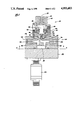
- FIG. 1 is a cross-sectional side elevation view of a positive displacement flow meter, having a bypass valve arranged according to one embodiment of the invention
- FIG. 2 is a view taken substantially along the lines 2--2 of FIG. 1, and shows sensing elements of the flow meter
- FIG. 3 is a cross-sectional side elevation view of the flow meter, showing the bypass valve arranged in accordance with another embodiment of the invention.
- the flow meter includes a housing 22 having an inlet 24 and an outlet 26.
- the housing also has a pair of semicircular openings 28 and 30 in which are received respective sensing elements or gears 32 and 34.
- the gears are mounted for rotation on respective shafts 36 and 38 in meshing engagement and are sized so that their teeth closely seal with but slide across the walls of the semicircular openings in which they are contained.
- Housing inlet passages 42 and 44 extend between the inlet 24 and an inlet chamber 46 to one side of the point of meshing of the gears, and an outlet chamber 48 on the other side of the point of meshing connects through housing outlet passages 50 and 52 to the outlet 26.
- a plate 54 is mounted on and sealed with the housing 22 to enclose the gears and semicircular openings.
- the housing and plate may conveniently be connected by fasteners (not shown) extended through aligned passages in the same, such as through passages 56 (FIG. 2) in the housing.
- the flow meter 20 is adapted to measure the volume flow rate and total volume flow of coating material supplied to spray coating apparatus (not shown), so that a selected amount of material may be applied onto an article.
- coating material is supplied under pressure and at a relatively low velocity flow rate to the housing inlet 24 and flows through the passages 42 and 44 to the inlet chamber 46.
- the coating material in the inlet chamber flows into and fills each gear tooth space 58 of the gears 32 and 34, and the pressure of the material on teeth 60 of the gears causes, with reference to FIG. 2, the gear 32 to rotate in a clockwise direction and the gear 34 in a counter-clockwise direction.
- each gear tooth space is filled with coating material as it passes through the inlet chamber. Then, as the gears continue to rotate, the material is confined in the tooth spaces by the surrounding walls of the openings 28 and 30 until it reaches the outlet chamber 48 where the gear teeth mesh and force the material out of the spaces and through the passage 50 and 52 to the housing outlet 26.
- the volumetric capacity of the tooth spaces 58 is known, so the revolutions through which the gears are turned represent a measurement of the volumetric flow of coating material through the flow meter.
- the flow meter 20 has a gear revolution detector 62.
- the detector may be a transducer which, with the housing 22 being of nonmagnetic material and the gears 32 and 34 of magnetic material, includes a magnetic pickup (not shown) extended into the housing and positioned to sense movement therepast of outer ends of the teeth 60 on one of the gears. The detector generates a signal each time the end of a gear tooth moves past the pickup, whereby the total number of signals generated represents the total volume flow of coating material through the flow meter and the rate at which the signals are generated represents the flow rate of material.
- the positive displacement flow meter 20 is of generally conventional structure and well suited for measuring the total volume flow and flow rate of coating material to spray coating apparatus. A difficulty arises, however, when it is used with color change equipment. Since the coating material passes through the flow meter, to change from spraying material of one color to spraying material of another, the flow meter must first be thoroughly cleaned to prevent contamination of coating material colors.
- the flow meter is connected between an outlet from a color changer (not shown) and an inlet to spraying apparatus (also not shown), and the flushing media normally comprises air and solvent that are alternately injected through the color changer and flow meter at a velocity that is relatively high with respect to the velocity of flow of coating material through the same. However, the flow meter is prone to failure when cleaned in such a manner.
- the flow meter is designed for specific flow ranges, and has limits on its internal operating speeds, i.e., the speeds of rotation of the gears or sensing elements 32 and 34.
- the air causes overdriving or too high a speed of rotation of the gears, which can result in damage to and failure of the flow meter.
- a second failure mode then occurs when solvent is injected into the flow meter following the air. When the liquid solvent hits the rapidly rotating gears, the impact causes severe stress and can result in damage to and failure of the flow meter.
- the flow meter 20 includes a bypass valve, indicated generally at 64.
- the bypass valve is closed.
- the bypass valve is opened to shunt some of the relatively high velocity flow of air and solvent around the gears or sensing elements 32 and 34, while still allowing a controlled and limited amount of air and solvent to pass by the gears to clean them.
- the controlled amount is sufficient to ensure proper cleaning of the gears without causing them to be too rapidly rotated and overdriven.
- bypass valve 64 is operable to selectively establish a path between a channel 66 in communication with the housing inlet passage 42 and a channel 68 in communication with the housing outlet passage 52, such that when the valve is opened a bypass or shunt path is established for a flow of some of the material introduced at the flow meter inlet 24 around the gears 32 and 34 and directly to the flow meter outlet 26.
- the bypass valve includes a cylinder end closure 70 having a chamber 72 in communication with the housing channels 66 and 68.
- a cylinder 74 is carried by the end closure, and a piston 76 having a piston rod 78 is reciprocable in the cylinder.
- the piston rod is slidable in and sealed with a passage through a guide 80, and channels 82 in the guide accommodate drain off of any material leaking into a space between a pair of seals that seal the piston rod and guide.
- a tapered valve 84 is at an end of the piston rod within the end closure opening 72, and is movable against and away from a valve seat 86 formed in the housing channel 68 to interrupt and establish a bypass or shunt path between the housing inlet and outlet passages 42 and 52 and around the gears 32 and 34.
- air under pressure is introduced at an inlet 88 to the cylinder to move the piston and tapered valve away from the seat against the urging of a spring 90, with an opening 92 in the cylinder accommodating escape of air from an opposite side of the piston.
- the pressure of air is removed from the inlet 88 for movement of the tapered valve against its seat by the spring.
- air under pressure may be applied to the piston through the opening 92.
- the flow meter 20 In a contemplated use of the flow meter 20, its inlet 24 is connected to an outlet from a color changer (not shown) and its outlet 26 is connected to an inlet to spray coating apparatus (also not shown).
- the bypass valve 64 is closed, so that all of the relatively low velocity liquid coating material flow supplied by the color changer to the spraying apparatus flows around and past the gears or sensing elements 32 and 34, causing them to rotate through a number of revolutions and at a rate that are directly in accordance with the total volume flow and flow rate of coating material to the spraying apparatus.
- the number of revolutions through which and the rate at which the gears are turned is sensed by the detector 62.
- the color changer, spraying apparatus, flow meter 20 and connecting lines must first be flushed clean of the previously supplied color of coating material to prevent contamination of the next color of coating material to be supplied. This is accomplished, as is conventional in the spray coating art, by applying alternate bursts of relatively high velocity flows of air and liquid solvent through the color changer and flow meter to the spraying apparatus. Absent the bypass valve 64, the flow meter could be damaged during flushing.
- the flow meter is designed for specific flow ranges, and has limits on the operating speed or rate of rotation of its gears or sensing elements 32 and 34.
- the air can cause overdriving or too high a rate or rotation of the gears, resulting in damage to and failure of the flow meter.
- a second failure mode can then occur when the solvent is injected into the flow meter following the air. When the liquid solvent hits the overdriven or rapidly rotating gears, the impact can cause severe stress and failure of the flow meter.
- the bypass valve 64 is opened to establish the shunt path through the channels 66 and 68 and divert some of the air and solvent around the gears 32 and 34, while still allowing a controlled and limited amount of air and solvent to contact and move past the gears to clean them.
- the shunt path presents some restriction or resistance to a flow of air and solvent, so a positive pressure differential exists between the inlet chamber 46 to and the outlet chamber 48 from the gears and the gears are rotated and thoroughly cleaned by the air and solvent.
- the restriction is not so great as to cause overdriving of the gears, but rather is such that the controlled amount of air and solvent moving past the gears is sufficient to ensure proper cleaning of the gears without causing them to be overdriven.
- the bypass valve is closed so that the total volume flow and volume flow rate of coating material next supplied to the coating apparatus is accurately measured.
- FIG. 3 shows another arrangement of flow meter and bypass valve contemplated by the invention.
- the flow meter 20' is substantially the same as the one in FIG. 1, except that bypass channels 66' and 68' are formed in the plate 54, so in this case the gear revolution detector 62 (not shown in FIG. 3) would be mounted on the side of the housing 22 opposite from the plate.
- the bypass valve 64 is mounted on the plate 54 to interrupt and establish communication between the inlet chamber 46 to and the outlet chamber 48 from the gears 32 and 34 opposite from the inlet passage 44 and outlet passage 50.
- the flow meter and bypass valve function in the same manner as described in respect of FIG. 1.
- bypass valve When the bypass valve is closed during a spray coating operation, all of the relatively low velocity flow of coating material supplied by the color changer flows past the gears, so that an accurate indication is provided of the volume flow rate and total volume flow of coating to the spraying apparatus.
- the bypass valve is opened to establish a shunt path around the gears, whereupon a controlled amount of air and solvent is carried through the gear tooth spaces 58 to clean the gears without overdriving them.
- an advantage of this particular arrangement is that, during flushing, the gear teeth 60 are exposed to the total volume flow of flushing media at the inlet and outlet chambers 46 and 48.
Abstract
Description
Claims (11)
Priority Applications (1)
| Application Number | Priority Date | Filing Date | Title |
|---|---|---|---|
| US07/324,389 US4953403A (en) | 1989-03-15 | 1989-03-15 | Positive displacement flushable flow meter |
Applications Claiming Priority (1)
| Application Number | Priority Date | Filing Date | Title |
|---|---|---|---|
| US07/324,389 US4953403A (en) | 1989-03-15 | 1989-03-15 | Positive displacement flushable flow meter |
Publications (1)
| Publication Number | Publication Date |
|---|---|
| US4953403A true US4953403A (en) | 1990-09-04 |
Family
ID=23263368
Family Applications (1)
| Application Number | Title | Priority Date | Filing Date |
|---|---|---|---|
| US07/324,389 Expired - Lifetime US4953403A (en) | 1989-03-15 | 1989-03-15 | Positive displacement flushable flow meter |
Country Status (1)
| Country | Link |
|---|---|
| US (1) | US4953403A (en) |
Cited By (16)
| Publication number | Priority date | Publication date | Assignee | Title |
|---|---|---|---|---|
| US5192425A (en) * | 1991-07-22 | 1993-03-09 | Wagner Spray Tech Corporation | Mounting base and assembly for pressure sensor, filter and pressure relief valve |
| US5490726A (en) * | 1992-12-30 | 1996-02-13 | Nordson Corporation | Apparatus for proportioning two components to form a mixture |
| US6196065B1 (en) * | 1996-04-29 | 2001-03-06 | Marconi Commerce Systems Gmbh & Co. Kg | Device metering and measuring quantities of liquid |
| US20030079786A1 (en) * | 2001-10-30 | 2003-05-01 | Diana Michael J. | Modular fluid pressure regulator with bypass |
| US20030122652A1 (en) * | 1999-07-23 | 2003-07-03 | Himmelstein Richard B. | Voice-controlled security with proximity detector |
| US20100156632A1 (en) * | 2008-10-27 | 2010-06-24 | Mueller International, Inc. | Infrastructure monitoring system and method |
| US20120305084A1 (en) * | 2011-05-31 | 2012-12-06 | Mueller International, Llc | Valve meter assembly and method |
| US8823509B2 (en) | 2009-05-22 | 2014-09-02 | Mueller International, Llc | Infrastructure monitoring devices, systems, and methods |
| US8855569B2 (en) | 2011-10-27 | 2014-10-07 | Mueller International, Llc | Systems and methods for dynamic squelching in radio frequency devices |
| US8931505B2 (en) | 2010-06-16 | 2015-01-13 | Gregory E. HYLAND | Infrastructure monitoring devices, systems, and methods |
| US20150190837A1 (en) * | 2012-09-19 | 2015-07-09 | Nordson Corporation | Metering device for a fluid |
| US20150375249A1 (en) * | 2013-02-18 | 2015-12-31 | Dürr Systems GmbH | Coating agent pump |
| US9494249B2 (en) | 2014-05-09 | 2016-11-15 | Mueller International, Llc | Mechanical stop for actuator and orifice |
| US9565620B2 (en) | 2014-09-02 | 2017-02-07 | Mueller International, Llc | Dynamic routing in a mesh network |
| US20190145810A1 (en) * | 2015-09-15 | 2019-05-16 | Avl List Gmbh | Device comprising a canned motor for measuring flow processes of measuring fluids |
| US10584704B2 (en) * | 2015-09-15 | 2020-03-10 | Avl List Gmbh | Flushable device for measuring flow processes of fluids |
Citations (6)
| Publication number | Priority date | Publication date | Assignee | Title |
|---|---|---|---|---|
| US1119401A (en) * | 1910-09-22 | 1914-12-01 | Thomas C Clifford | Meter system. |
| US1307337A (en) * | 1919-06-24 | Water-meter | ||
| US2258878A (en) * | 1939-02-20 | 1941-10-14 | Bank Of America Nat Trust | Fluid metering device |
| US3813940A (en) * | 1972-12-18 | 1974-06-04 | Sperry Rand Corp | Flow meter with a bypass |
| US4400147A (en) * | 1981-03-25 | 1983-08-23 | Binks Manufacturing Company | Flushable rotary gear pump |
| US4840063A (en) * | 1987-05-14 | 1989-06-20 | Westinghouse Electric Corp. | Fail safe valve for an air inleakage monitoring system in a steam turbine |
-
1989
- 1989-03-15 US US07/324,389 patent/US4953403A/en not_active Expired - Lifetime
Patent Citations (6)
| Publication number | Priority date | Publication date | Assignee | Title |
|---|---|---|---|---|
| US1307337A (en) * | 1919-06-24 | Water-meter | ||
| US1119401A (en) * | 1910-09-22 | 1914-12-01 | Thomas C Clifford | Meter system. |
| US2258878A (en) * | 1939-02-20 | 1941-10-14 | Bank Of America Nat Trust | Fluid metering device |
| US3813940A (en) * | 1972-12-18 | 1974-06-04 | Sperry Rand Corp | Flow meter with a bypass |
| US4400147A (en) * | 1981-03-25 | 1983-08-23 | Binks Manufacturing Company | Flushable rotary gear pump |
| US4840063A (en) * | 1987-05-14 | 1989-06-20 | Westinghouse Electric Corp. | Fail safe valve for an air inleakage monitoring system in a steam turbine |
Cited By (32)
| Publication number | Priority date | Publication date | Assignee | Title |
|---|---|---|---|---|
| US5192425A (en) * | 1991-07-22 | 1993-03-09 | Wagner Spray Tech Corporation | Mounting base and assembly for pressure sensor, filter and pressure relief valve |
| US5490726A (en) * | 1992-12-30 | 1996-02-13 | Nordson Corporation | Apparatus for proportioning two components to form a mixture |
| US6196065B1 (en) * | 1996-04-29 | 2001-03-06 | Marconi Commerce Systems Gmbh & Co. Kg | Device metering and measuring quantities of liquid |
| US20030122652A1 (en) * | 1999-07-23 | 2003-07-03 | Himmelstein Richard B. | Voice-controlled security with proximity detector |
| US20030079786A1 (en) * | 2001-10-30 | 2003-05-01 | Diana Michael J. | Modular fluid pressure regulator with bypass |
| EP1308816A1 (en) * | 2001-10-30 | 2003-05-07 | Illinois Tool Works Inc. | Modular fluid pressure regulator with bypass |
| US20040154675A1 (en) * | 2001-10-30 | 2004-08-12 | Diana Michael J. | Modular fluid pressure regulator with bypass |
| US6874534B2 (en) | 2001-10-30 | 2005-04-05 | Illinois Tool Works Inc. | Modular fluid pressure regulator with bypass |
| US9934670B2 (en) | 2008-10-27 | 2018-04-03 | Mueller International, Llc | Infrastructure monitoring system and method |
| US9202362B2 (en) | 2008-10-27 | 2015-12-01 | Mueller International, Llc | Infrastructure monitoring system and method |
| US20100156632A1 (en) * | 2008-10-27 | 2010-06-24 | Mueller International, Inc. | Infrastructure monitoring system and method |
| US9799204B2 (en) | 2009-05-22 | 2017-10-24 | Mueller International, Llc | Infrastructure monitoring system and method and particularly as related to fire hydrants and water distribution |
| US8823509B2 (en) | 2009-05-22 | 2014-09-02 | Mueller International, Llc | Infrastructure monitoring devices, systems, and methods |
| US9861848B2 (en) | 2010-06-16 | 2018-01-09 | Mueller International, Llc | Infrastructure monitoring devices, systems, and methods |
| US8931505B2 (en) | 2010-06-16 | 2015-01-13 | Gregory E. HYLAND | Infrastructure monitoring devices, systems, and methods |
| US9849322B2 (en) | 2010-06-16 | 2017-12-26 | Mueller International, Llc | Infrastructure monitoring devices, systems, and methods |
| US8833390B2 (en) * | 2011-05-31 | 2014-09-16 | Mueller International, Llc | Valve meter assembly and method |
| US20120305084A1 (en) * | 2011-05-31 | 2012-12-06 | Mueller International, Llc | Valve meter assembly and method |
| US11015967B2 (en) | 2011-05-31 | 2021-05-25 | Mueller International, Llc | Valve meter assembly and method |
| US10655999B2 (en) | 2011-05-31 | 2020-05-19 | Mueller International, Llc | Valve meter assembly and method |
| US8855569B2 (en) | 2011-10-27 | 2014-10-07 | Mueller International, Llc | Systems and methods for dynamic squelching in radio frequency devices |
| US10039018B2 (en) | 2011-10-27 | 2018-07-31 | Mueller International, Llc | Systems and methods for recovering an out-of-service node in a hierarchical network |
| US20150190837A1 (en) * | 2012-09-19 | 2015-07-09 | Nordson Corporation | Metering device for a fluid |
| US10155242B2 (en) * | 2012-09-19 | 2018-12-18 | Nordson Corporation | Metering device for a fluid |
| US9662673B2 (en) * | 2013-02-18 | 2017-05-30 | Durr Systems Gmbh | Coating agent pump |
| US20150375249A1 (en) * | 2013-02-18 | 2015-12-31 | Dürr Systems GmbH | Coating agent pump |
| US9909680B2 (en) | 2014-05-09 | 2018-03-06 | Mueller International, Llc | Mechanical stop for actuator and orifice |
| US9494249B2 (en) | 2014-05-09 | 2016-11-15 | Mueller International, Llc | Mechanical stop for actuator and orifice |
| US10871240B2 (en) | 2014-05-09 | 2020-12-22 | Mueller International, Llc | Mechanical stop for actuator and orifice |
| US9565620B2 (en) | 2014-09-02 | 2017-02-07 | Mueller International, Llc | Dynamic routing in a mesh network |
| US20190145810A1 (en) * | 2015-09-15 | 2019-05-16 | Avl List Gmbh | Device comprising a canned motor for measuring flow processes of measuring fluids |
| US10584704B2 (en) * | 2015-09-15 | 2020-03-10 | Avl List Gmbh | Flushable device for measuring flow processes of fluids |
Similar Documents
| Publication | Publication Date | Title |
|---|---|---|
| US4953403A (en) | Positive displacement flushable flow meter | |
| US4400147A (en) | Flushable rotary gear pump | |
| US4481805A (en) | Meter prover apparatus and method | |
| DE10355250B4 (en) | Method for determining leaks of a pressure fluid in a pressure actuated machine using a mathematical equation relating pressure and flow volume and comparing actual values to a reference value | |
| US3457768A (en) | Meter proving | |
| US4062220A (en) | Fluid measuring and metering system | |
| US4606218A (en) | Compact bidirectional meter prover mechanism | |
| CA2317445A1 (en) | Friction flowmeter | |
| DE19927117A1 (en) | Measuring device for detecting leakage from hydraulic components has pressure senor for measuring pressure in piston and displacement sensor for piston rod path | |
| USRE31432E (en) | Apparatus and method for determining the characteristic of a flowmeter | |
| JP2008286765A (en) | Leak detecting method | |
| WO2020048947A1 (en) | A method for detecting leakage in a positive displacement pump | |
| US5616862A (en) | Volume meter | |
| US4984461A (en) | Fluid flow sensor | |
| EP0220636B1 (en) | Fluid flow sensor | |
| US20210293234A1 (en) | Reciprocating piston pump | |
| US3685354A (en) | Flow indicator device having pressure balanced sealing shaft | |
| US4802362A (en) | Fluid flow sensor | |
| JP4885597B2 (en) | Mixing equipment | |
| GB2129569A (en) | Flowmeter prover | |
| JP2613548B2 (en) | Method and system for controlling coating amount of viscous coating material | |
| JP2863395B2 (en) | Piston prober | |
| EP0927876B1 (en) | Compensation of coriolis meter motion induced signal | |
| JP3046365B2 (en) | Flowmeter test equipment | |
| JPH03218415A (en) | Method and apparatus for standardizing meter |
Legal Events
| Date | Code | Title | Description |
|---|---|---|---|
| AS | Assignment |
Owner name: BINKS MANUFACTURING COMPANY, A CORP. OF DE., ILLIN Free format text: ASSIGNMENT OF ASSIGNORS INTEREST.;ASSIGNOR:SPRINGER, CARL M.;REEL/FRAME:005317/0606 Effective date: 19890313 |
|
| STCF | Information on status: patent grant |
Free format text: PATENTED CASE |
|
| FEPP | Fee payment procedure |
Free format text: PAYOR NUMBER ASSIGNED (ORIGINAL EVENT CODE: ASPN); ENTITY STATUS OF PATENT OWNER: LARGE ENTITY |
|
| FPAY | Fee payment |
Year of fee payment: 4 |
|
| FPAY | Fee payment |
Year of fee payment: 8 |
|
| AS | Assignment |
Owner name: FIRST NATIONAL BANK OF CHICAGO, THE, ILLINOIS Free format text: SECURITY AGREEMENT;ASSIGNOR:BINKS SAMES CORPORATION;REEL/FRAME:009046/0559 Effective date: 19980316 |
|
| AS | Assignment |
Owner name: ILLINOIS TOOL WORKS INC., ILLINOIS Free format text: SECURITY INTEREST;ASSIGNOR:BINKS SAMES CORPORATION;REEL/FRAME:009678/0215 Effective date: 19980316 Owner name: ILLINOIS TOOL WORKS INC., ILLINOIS Free format text: ASSIGNMENT OF ASSIGNORS INTEREST;ASSIGNOR:BINKS SAMES CORPORATION;REEL/FRAME:009678/0137 Effective date: 19980831 |
|
| FPAY | Fee payment |
Year of fee payment: 12 |