US4951222A - Method and system for dimensional and weight measurements of articles of manufacture by computerized tomography - Google Patents
Method and system for dimensional and weight measurements of articles of manufacture by computerized tomography Download PDFInfo
- Publication number
- US4951222A US4951222A US07/204,588 US20458888A US4951222A US 4951222 A US4951222 A US 4951222A US 20458888 A US20458888 A US 20458888A US 4951222 A US4951222 A US 4951222A
- Authority
- US
- United States
- Prior art keywords
- block
- detectors
- corner
- ray
- fan
- Prior art date
- Legal status (The legal status is an assumption and is not a legal conclusion. Google has not performed a legal analysis and makes no representation as to the accuracy of the status listed.)
- Expired - Lifetime
Links
Images


Classifications
-
- G—PHYSICS
- G06—COMPUTING; CALCULATING OR COUNTING
- G06G—ANALOGUE COMPUTERS
- G06G7/00—Devices in which the computing operation is performed by varying electric or magnetic quantities
- G06G7/48—Analogue computers for specific processes, systems or devices, e.g. simulators
- G06G7/68—Analogue computers for specific processes, systems or devices, e.g. simulators for civil engineering structures, e.g. beam, strut, girder, elasticity computation
-
- G—PHYSICS
- G01—MEASURING; TESTING
- G01B—MEASURING LENGTH, THICKNESS OR SIMILAR LINEAR DIMENSIONS; MEASURING ANGLES; MEASURING AREAS; MEASURING IRREGULARITIES OF SURFACES OR CONTOURS
- G01B15/00—Measuring arrangements characterised by the use of electromagnetic waves or particle radiation, e.g. by the use of microwaves, X-rays, gamma rays or electrons
- G01B15/02—Measuring arrangements characterised by the use of electromagnetic waves or particle radiation, e.g. by the use of microwaves, X-rays, gamma rays or electrons for measuring thickness
- G01B15/025—Measuring arrangements characterised by the use of electromagnetic waves or particle radiation, e.g. by the use of microwaves, X-rays, gamma rays or electrons for measuring thickness by measuring absorption
-
- G—PHYSICS
- G01—MEASURING; TESTING
- G01N—INVESTIGATING OR ANALYSING MATERIALS BY DETERMINING THEIR CHEMICAL OR PHYSICAL PROPERTIES
- G01N23/00—Investigating or analysing materials by the use of wave or particle radiation, e.g. X-rays or neutrons, not covered by groups G01N3/00 – G01N17/00, G01N21/00 or G01N22/00
- G01N23/02—Investigating or analysing materials by the use of wave or particle radiation, e.g. X-rays or neutrons, not covered by groups G01N3/00 – G01N17/00, G01N21/00 or G01N22/00 by transmitting the radiation through the material
- G01N23/04—Investigating or analysing materials by the use of wave or particle radiation, e.g. X-rays or neutrons, not covered by groups G01N3/00 – G01N17/00, G01N21/00 or G01N22/00 by transmitting the radiation through the material and forming images of the material
- G01N23/046—Investigating or analysing materials by the use of wave or particle radiation, e.g. X-rays or neutrons, not covered by groups G01N3/00 – G01N17/00, G01N21/00 or G01N22/00 by transmitting the radiation through the material and forming images of the material using tomography, e.g. computed tomography [CT]
-
- B—PERFORMING OPERATIONS; TRANSPORTING
- B21—MECHANICAL METAL-WORKING WITHOUT ESSENTIALLY REMOVING MATERIAL; PUNCHING METAL
- B21B—ROLLING OF METAL
- B21B2261/00—Product parameters
- B21B2261/02—Transverse dimensions
- B21B2261/04—Thickness, gauge
-
- G—PHYSICS
- G01—MEASURING; TESTING
- G01N—INVESTIGATING OR ANALYSING MATERIALS BY DETERMINING THEIR CHEMICAL OR PHYSICAL PROPERTIES
- G01N2223/00—Investigating materials by wave or particle radiation
- G01N2223/40—Imaging
- G01N2223/419—Imaging computed tomograph
Definitions
- This invention relates to a device and method for measuring cross-sectional or edge boundary dimensions and the weight per unit length, typically weight per foot (WPF). More particularly, the invention relates to the measuring of the edge boundaries of steel products by computerized tomography during rolling thereof.
- WPF weight per foot
- the principal parameters for controlling manufacturing operating conditions are weight per unit length, i.e., weight per foot, measurements in combination with measurements of several key dimensions.
- many dimensional measurements are required, preferably to ultimately obtain a cross-sectional profile of the product.
- the prior art methods of obtaining these measurements generally involve taking optical measurements of the object dimensions, determining cross-sectional area and then multiplying the product cross-sectional area by its density.
- weight per unit length measurement accuracies of up to about 0.1%.
- optical measurement of the cross-sectional profile of complex shapes such as I-beams, pipes or tubing is very difficult due to an inaccessibility to the inner surface thereof.
- the prior art also teaches the use of radiation transmission for measuring the product thickness, typically of flat rolled products. Although results regarding measurements of product thickness have been generally good using these techniques, no known prior art method has taught how to use product dimension determination by radiation transmission to determine the edge boundaries of cross-sectional area, and/or weight per unit length of various products, especially complicated and intricate shapes.
- a tomographic apparatus which is adapted for generating a reconstructed image and the dimensions of a planar section of a product which is movable along an axis of inspection.
- the apparatus includes at least one, and preferably three fan-shaped radiation sources, e.g., ⁇ -rays, aimed at a planar section of the product, adapted for generating radiation at a level sufficient to penetrate the product, i.e., at least about 500- KeV, preferably at least 660 KeV, revolvable about said product in said plane, and adapted to scan said product plane at said axis.
- a stationary ring of radiation detectors is arranged so that the detectors are equally, i.e, equidistant from the center-line at all points, spaced around the product planar section outside of a radiation source scanning circle, and each of the detectors are adapted to provide an output which is a function of radiation absorption by the product, and consequently by the detector, in the scan plane.
- Computing means responsive to the radiation detector output signals is provided associated with the detectors for reconstructing the product planar image and calculating the product dimensions by detecting its edges. This is done by digitizing and assembling the signals from the detectors.
- Display means is also associated with the computing means and is responsive to the computing means for displaying the product's reconstructed planar image and dimensions.
- the computing means is also adapted to generate weight-per-unit length, i.e., weight-per-foot values from known product density values and to provide such information for process control purposes.
- the invention comprises a method determining a product's planar dimensions and weight-per-unit length by a tomographic inspection with ⁇ -rays. More particularly, in a preferred embodiment, three ⁇ -ray sources are revolved about a product object within the same plane to penetrate said object in said plane with a fan-shaped beam of ⁇ -ray radiation. A circular array of detectors are positioned in the same plane outside the ⁇ -ray sources. The radiation is detected from said sources passing through the product object, and based on the radiation detected, computing means determines the dimensions of the product, and/or the weight-per-unit length thereof.
- the detector data are compensated, (at each point in the fan beam), for system electrical offsets and individual detector gain characteristics.
- This compensation arrangement includes direct measurement of the offsets, and considers the effect of sample interval time on the measurement.
- FIG. 1A is a cross-sectional view of the tomographic scanner for generating dimensions and weight measurements of an object passed along the axis of inspection according to the invention.
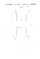
- FIG. 1B shows, in functional block diagram form, the scanning system of FIG. 1A.
- FIG. 2 shows alternate embodiment of the scanning system of FIG. 1, showing three gamma radiation sources instead of a single source.
- FIG. 3 shows an example of an object undergoing scanning by the scanning system of FIG. 1.
- FIGS. 4-6 depict the corner location process for determining the corner coordinates of the object.
- FIGS. 7-8 illustrate the process for determining the inner corner coordinates of the web of the
- FIGS. 9-10 are diagrams illustrating the process for determining the thickness of the flange of the object.
- FIGS. 11A-N are flow diagrams depicting the software analysis for dimensioning an object using the scanning system of FIG. 1.
- FIGS. 12A-B show a flow diagram of a sub-routine that calculates expected dimensions of an object to establish a starting point for the dimensioning routine of FIGS. 11A-C.
- FIGS. 13A-D show the physical composition of gamma radiation detector of the scanning system of FIG. 1.
- FIG. 13E illustrates the electronic circuitry of the gamma radiation detector of FIGS. 13A-D.
- FIG. 13F is a graph showing the relationship between the voltage output of the detector and the angle of incidence of radiation.
- scanner 12 which comprises at least one gamma radiation source 16 and a circular array or ring of gamma radiation detectors 14 which are arranged in the same plane as gamma radiation source 16.
- Gamma radiation source 16 projects a fan-shaped beam 24 along a plane perpendicular to the longitudinal axis of an object 22 under scan.
- Source 16 generates radiation of at least 650 KeV, sufficient to penetrate inanimate object 22 such as steel beams.
- the preferred embodiment of scanner 12 is designed to operate in a steel mill in sequence with the completion of the rolling process of steel objects such as I-beams.
- the I-beam which may be produced by the rolling mill in lengths of eighty to two hundred feet may be scanned and accurately measured by scanner 12 to determine whether dimensional tolerance is within specification and to determine the weight per unit length, e.g. weight per foot, averaged over the entire length of the beam.
- the radiation produced by gamma radiation source 16 is detected by detectors 14.
- detectors 14 To enhance resolution, a substantially large number of detectors 14 is used.
- scanner 12 may include one hundred twenty eight detectors 14.
- Detectors 14 detect fan-shaped beam 24 made up of fan rays 24a-24n, with the intensity of each fan ray (24a-24n) or element varying according to the medium through which the fan elements 24a-24n pass.
- a fan ray 24a-24n passing through air has a much greater intensity than a ray 24a-24n which passes through object 22. This is due, in part, to scatter effect 32 (FIG. 3) which is caused by a deflection of the radiation particles by the object being radiated and the absorption of radiation when passing through material of substantial density.
- source 16 rotates along path 18 constantly emitting radiation.
- a snapshot taken by detectors 14 is produced and transmitted to a computer 114 (FIG. 1B) to determine the radiation intensity received by each detectors 14 from source 16 at that instant.
- Path 18 traveled by source 16 extends completely around object 22 inside the circle defined by detectors 14. In this way there is presented a complete image of the object 22 being scanned. At the same time, object 22 moves along a transport means, such as a conveyor belt, (not shown). The effect of rotating source 16 in the plane of detectors 14 together with the travel of object 22 in a longitudinal direction perpendicular to the plane of detectors 14 produces a helical image of object 22. This helical image is then compressed to provide a cross-sectional representation of object 22.
- FIG. 1B shows in functional block diagram form scanning system 10 including scanner 12. Each detector 14 is coupled to detector assembly 90.
- the position of radiation source 16 is transmitted to scanner timing and control block 92, coupled to encoder 3, in whi39ch the location and the time of each scan is recorded in accordance with a clock signal from a clock 94.
- the information from timing and control block 92 and detector assembly block 90 are applied to data multiplexer and digitizer 96 which places the information in a form and sequence readable by computer 114 which includes data acquisition and sampling block 98 as well as control and dimension calculation block 104.
- Temperature is monitored by product temperature monitor and mill sensor block 102.
- the temperature readings of block 102 are applied to computer 114 to account for variations in physical properties due to varying temperatures.
- Also applied to data acquisition and sampling controller block 98 is information from operator control panel 100.
- the information from control panel 100 is then transferred from block 98 to the control and dimension calculation block 104 where a determination is made of (1) the ideal dimensions of object 22 to be compared and (2) the actual dimensions of object 22 being scanned.
- the ideal dimensions of object 22 are stored in product identification block 106.
- the ideal dimensions, received by way of block 106, as well as the actual dimensions of object 22 are then applied by block 104 to product dimension display 108.
- Display 108 shows the dimensions of object 22 for each of two scans that are run by scanner 12 of system 10 on object 22 as well as an average of the information from both of these scans.
- control and dimension calculation block 104 is also applied by control and dimension calculation block 104.
- the dimension and weight per foot is applied by block 104 to block 110 to show the amount of material that is being rolled into object 22.
- Complete image reconstruction is not essential since all relevant information has been gathered by determining selective coordinates along the boundaries of object 22 and using this information to determine deviations from an ideal and whether the deviations exceed the tolerance specifications.
- the information from computer 114 may be applied to image reconstruction processor 112 to generate a complete image of object 22 being scanned.
- FIG. 2 shows scanner 12a which is an alternate embodiment of scanner 12.
- Scanner 12a includes three fixed gamma radiation sources 115a, 115b, 115c, instead of a single gamma radiation source 16.
- the advantages of scanner 12a include a reduction in moving parts and a reduction in the possibility of failure in operation.
- Another advantage of scanner 12a is the ability to obtain a complete instantaneous imaging snapshot instead of a compressed helical representation. This lends itself to constant scanning of a single object 22 instead of the variety of objects 22 which may be effectively scanned by rotating source 16 of scanner 12.
- FIG. 3 for purposes of explanation there is shown an example of object 22 undergoing scanning by gamma radiation source 16 with detectors 14a-14n illuminated by fan beam 24.
- Each fan element 24a-24n intersects with respective detectors 14a-14n.
- fan elements 24b-24f intersect object 22 and produce a scatter effect 32.
- a scatter effect 32 occurs when the gamma radiation particles are deflected by the object being irradiated or scanned. The scatter effect causes radiation to be detected by detectors 14 which would otherwise not be in the path of the fan element.
- Scatter path 34a and 34b are illustrative of the increased radiation that a detector 14 such as detector 14d receives from fan elements other than the direct line of sight fan element 24d which would normally illuminate detector 14d.
- Other scatter paths are not shown but it is understood by those skilled in the art that multiple detectors 14a-n will pick up or detect the scattered radiation after a fan element passes through the object 22. This is often referred to as the Compton effect or Compton scatter effect. Readings from the detectors are processed to account for and correlate the information in response to these Compton scatter effects.
- the ideal or model dimensions of object 22 being scanned are used to locate fan elements 24 near or at the point where the corners or outer boundary points of object 22 should be located. This is a preorientation of source 16 positions to approximate the location of object 22. It is the detection of the intensity of the radiation produced by gamma radiation source 16 which determines the location of object 22, because the varying intensities detected by detectors 14a-n provide information corresponding to the location of object 22. In order to determine the exact position of object 22 it is essential to establish at what point a first fan element 24a-n passes through object 22 in which the next adjacent fan element 24a-n fails to pass through object 22.
- corner location process 40 whereby a fan element 44 is interpolated to a line intersecting a corner of object 22.
- This result is derived from fan element 24n which is determined to pass through object 22 and fan element 24n-l which is determined to not pass through object 22. These determinations are made in response to the intensity of the radiation detected by detector 14n.
- Fan elements 24n and 24n-l are detected by detector 14n as source 16 travels along path 18. Using the equations (which will later be given) for the fan elements or lines that pass through object 22 and those fan elements which do not pass through object 22, respectively, allows for the interpolation of a fan element 44 between the lines which intersect the corner of the object in question.
- FIG. 5 there is shown an exploded view of area 42 corresponding to the corner of object 22 and the fan elements 24n, 24n-l and interpolated fan element, or line 44.
- Distance 48 affects the intensity of fan element 24n passing through object 22 at that point which is the determining factor in establishing the outermost fan element which passes through object in the region of corner 46.
- the outcome of this process of corner location establishes an interpolated line which is tangent to point 46. This process is repeated as gamma radiation source 16 travels along path 18. By repeating the process, a series of interpolated lines tangent to point 46 are established and the intersection of said interpolated lines will provide the exact coordinates of point 46.
- FIG. 6 shows the four sets of interpolated lines whose intersection provides the coordinates of respective corners 46, 52, 60 and 56.
- the coordinates of corner 46 are established by determining the point of intersection of interpolated lines 44 and 44a.
- the coordinates of corner 52 are established by determining the point of intersection of interpolated lines 54 and 54a.
- the coordinates of corner 60 are established by determining the point of intersection of interpolated lines 62 and 62a.
- the coordinates of corner 56 are established by determining the point of intersection of interpolated lines 58 and 58a.
- the coordinates of all four outer boundary or outer corner points are established and recorded by scanner system 10.
- FIG. 11A there is shown flowchart 150, an overview of the dimensioning software which is written in Fortran for a Digital Equipment Corp. VMS Computer and which appears as Appendix A.
- This software is used to analyze an object 22.
- Block 152 provides for corner ray selection. Once the corner rays are selected, the coordinates of the corners of object 22 are determined in block 154.
- Block 156 uses the corner coordinates, determined in block 154, to select detectors 14 for the flange thickness measurement which takes place in block 158.
- Block 160 determines the thickness of the web section.
- Block 162 measures the offset of the web section and block 164 calculates a thermal correction based on the web temperature.
- Block 166 begins a process which loops through the corners of object 22 being scanned starting with corner a on the upper left-hand side through corners b, c and d numbered clockwise around object 22, as shown in FIG. 6.
- the purpose of the loop beginning at block 166 is to determine the equations of a number of lines that are tangent to the corners of object 22.
- Block 168 starts a loop through detectors chosen in preliminary sub-routine 560. These detectors were chosen such that they would have rays that passed through the corner but not through other parts of object 22 being scanned.
- the dimensioning routines assume an x-y coordinate system with the starting location for detector 14 being the origin of the coordinate system.
- Block 170 initializes the ray numbers which are used in flow diagram 152.
- the ray numbers are those selected in subroutine 560 for each detector 14 selected in subroutine 560, one ray number for each detector.
- the rays selected are those that pass closest to each of the ideal corner locations of object 22 being evaluated. These rays are a starting point that allow processing to move optimally from the ideal corner position to the actual corner position as data from object 22 is processed.
- Block 172 is a decision block in which a determination is made where the selected detector 14 is positioned relative to the corner positions. For example, for corners a and b which are on the top of an I-beam, if detector 14 is to the left of the corner then the ray numbers would increase moving toward the center of the section (FIG. 6). On the other hand, if the selected detector 14 were to the right of the corner, the ray numbers would decrease moving toward the center of the section. If the ray numbers decrease moving toward the section center, a "Yes" results from decision block 172 and processing moves on to decision block 174. In decision block 174 a determination is made whether the selected ray, as initialized in block 170, has a thickness value greater than a predetermined threshold value.
- the predetermined threshold is in the computer 114. If the thickness value is greater than the specified threshold value, the ray is assumed to pass through object 22. It is necessary to select rays further away from the center of object 22, i.e., with higher ray numbers, in order to find the corner.
- Block 184 begins a loop which sequences from the ray number that was initialized, as described above, to the maximum possible ray number for the scanner.
- the selected ray does not pass through the corner and the ray numbers must be decremented in order to get rays closer to the center of object 22. This is done in block 176 which starts a loop where the rays move from the initial ray chosen to the minimum possible ray.
- the loop including blocks 176, 178, 180 acts very much the same as the loop including blocks 184, 186, 188.
- block 178 checks whether the new ray number has a thickness value greater than the threshold value. If it does, then a corner has been detected and that ray is selected as both the ray passing through the corner and the ray closest to it. If the thickness value is still below the threshold value, then execution proceeds through block 180 and back to block 176. As in the loop including blocks 184, 186, 188 if the end of the loop is encountered (the extreme or minimum ray number), then an error has occurred and block 182 calls the error message subroutine and execution exits routine 152 via off-page connector G1.
- Taking the "No" path from decision block 172 means that if it is necessary to select rays closer to the object center, this can be done by increasing the ray number or move away from the object center by decreasing ray number.
- Processing moves through off-page connector A3 to decision block 194 (FIG. 11C). Again a check is made to determine whether the thickness value of the initial ray is greater than the threshold value as shown in decision 194. If it is, control moves to block 220 where a loop is initiated from the initial ray to the minimum possible ray. After the ray number is decremented, a determination is made whether the thickness value is less than the threshold value.
- control moves through decision block 224 back to block 220, where the ray number is decremented and a check is made on the thickness value in block 222. Eventually, the thickness value will be less than the threshold value and a "Yes" results at block 222. Control then moves to block 226 where the ray number is incremented. This backs up one ray so that the current ray number is the one that passes through the corner and closest to it. Control moves to decision block 230.
- FIG. 4 and 5 there is a ray 24n that passes through the corner and the thickness value 48 for that ray is known. Furthermore, the position of the next ray away from the corner, that is, the previous ray 24n-l which does not pass through the corner is known. Thus a distance from ray 24n to the corner can be calculated based on the thickness value. The calculated distance is the perpendicular distance from the ray 24n passing through the corner to an ideal ray 44 tangent to the actual corner position.
- decision block 232 a determination is made whether the current detector 14 is to the right or left of the corner position. The purpose of doing this is because in the next two blocks, blocks 236 and 234, calculation is made of the slope of a new line (line 44 in FIG. 5) which passes through the detector and through the actual corner position based on the distance correction that was calculated in block 230.
- Block 240 is not used in general in dimensioning I beams or wide flange sections but instead for objects with rounded corners.
- decision block 242 a determination is made whether all detectors 14 have been sequenced through for the particular corner that is being scanned. If “Yes”, then control goes to decision block 244. If "No”, control goes back to block 168 and the process is repeated for the next detector 14. If control moves to block 244, a determination is made whether all outside corners have been sequenced. If not, control goes back to block 166 and the process is repeated for the next corner. If all four corners are completed, then the control is taken via off-page connector B and the corner coordinate calculation routine 154 is initiated.
- routine 152 the rays which pass through the object very close to the corner for each detector 14 are determined and then an equation of a line that passes exactly through the corner of object 22 is calculated for each detector 14 and for each corner. Thus, approximately fifty to sixty independent lines have been determined which pass through each corner.
- routine 154 the intersection points for pairs of these lines are calculated.
- a loop is initialized through the four corners.
- variables are initiated to be used internally in this routine for averaging the corner coordinates.
- loop 1 is initiated through the rays selected for the corner.
- a second loop (loop 2) is initiated, sequencing through the same rays as block 250 so that there is a loop within a loop sequencing through these ray numbers.
- decision block 254 a determination is made whether the slope of the loop 2 ray, differs from the slope of the current ray in block 250 (loop 1) by a certain minimum amount. For the example, I-beam of FIGS. 4 and 5, 60 degrees is chosen as the minimum slope difference. Requiring that a minimum slope difference exist between lines whose intersection coordinates are to be determined both reduces the potential errors in the coordinate calculations and limits the number of solutions to a reasonable number. This means that the difference in slope between the lines must be at least a minimum value. If the slopes do not differ by at least 60 degrees, control moves to decision block 62 where if loop 2 is not complete, control goes back to block 252.
- Block 252 increments the ray number and the next ray goes through loop 2. If, however, the slopes do differ by at least 60 degrees in block 254, control moves to block 256 where the x,y coordinates of the intersection of the two lines are determined. In block 258 the x coordinate and y coordinate are separately summed into running sums of the x's and y's determined for all of the intersections of the lines for this corner. In block 260, the summing index is incremented. In decision block 262 if all rays have not been incremented through, control goes back to block 254 and the process is repeated until the total number of rays for loop 2 is exhausted. At this point, control drops down to decision block 264 which checks that all of the rays for loop 1 have been incremented through. If not, control goes back to block 250 and the loops are repeated until all intersections) have been calculated.
- Control then moves on to block 266 where the x's and y's for the line intersections summed in block 258 are averaged to determine an average x and y coordinate for the corner position. Control then moves on to decision block 268 where a determination is made whether all outer corners have been examined. If not, control goes to block 246 where routine 154 is repeated. If all outer corners have been examined, control moves ahead to block 270 and a calculation of the angles of the beam flanges from the vertical is made. This is used in a later routine as a correction factor when determining the thickness of the beam flanges.
- flange thickness detector routine 156 The purpose of this routine is to select appropriate detectors that can be used for determining flange thickness for each of the four flanges (half flanges between the web and the four corners of an I-beam). The method used for this is to first determine the web position based on the corner positions known from routine 156. Then, for each flange, to select detectors which have rays that pass through that flange and through no other part of the object. Using corner 1 (upper left-hand corner in the present embodiment) as an example, detectors that are to the left of the section and which are below the web are selected. This process begins in block 272 by first calculating the web y position. Next in block 274, a loop is initiated through detectors 62 to 70 to find which of these detectors is the first to have its y coordinate below the y position of the web.
- corner 1 upper left-hand corner in the present embodiment
- decision block 276 a determination is made whether the detector y is less than the web y. If the answer is "No", control loops back to decision block 280 to determine if the loop is complete. Then, if not, control goes back to block 274 where the detector number is incremented and then back to decision block 276 to again determine whether the detector y is less than the web y position. Assuming that it is, the first detector on the right side of the section that is below the web is now determined. Detectors in this area may be used for measuring the flange thickness for the flange of corner 2 (upper right corner). The first detector that is actually used for the flange of corner 2 would be two detector numbers greater than that just determined as being the first below the web. That plus the next thirteen detectors in sequence would be used for measuring the thickness of the flange of corner 2.
- a selection by calculation may be made of the first detector to be used for corners 1, 3 and 4.
- the first detector for corner 1 would be in the range of perhaps 127 and the detectors then used would be 127 plus the next thirteen detectors in sequence in decreasing order, So it would be 127, 126, 125, etc. That completes the flange thickness detector selections and control moves to the flange thickness measurement loop.
- decision block 280 if all detectors are sequenced through and a detector has not been found below the web, an error condition has been encountered. When this error condition is raised, control exits from block 280 in the yes direction to off-page connector G1 to output an error message and to terminate the program.
- routine 150 the detectors 14 selected in routine 156 are used to determine the thickness of the flanges between the corner and the web of the section of object 22. This is accomplished by dividing the flange into three separate links as shown FIG. 9, and then summing the thickness values of the rays on the selected detectors 14 through each of those linked segments and finally taking the average values for each segment.
- Routine 158 starts with block 282 which initiates a loop through the four corners of the section.
- block 284 initializes to zero the variables used for summing up the thickness values for each of the segments, as well as the index variables.
- block 286 the x and y coordinates of each end of the three flange segments are calculated. This is done based on the previously determined corner location and the assumed web position. The segment end points nearest the corner end of the flange would be, for example, the corner coordinates determined in 154 translated a fixed distance toward the web so that the thickness summing does not see the corner of the section. If the reduced thickness at the corners were included in the flange thickness an error would be introduced into the thickness indication.
- the x and y coordinates of the web-flange junction are calculted and translated a fixed distance up the flange to determine that segment endpoint. Again the translation is done so that the increasing thickness seen at the web would not enter into the thickness summing for the flange thickness.
- the intermediate segment endpoint coordinates are calculated by interpolating between the now-known corner and web endpoints.
- a loop is initiated through the fourteen detectors chosen for the thickness summing for each corner.
- the slope from the detector to the thickness summing endpoint near the flange end in block 286 is calculated.
- the slope from the detector to a point one-third down the flange from the prior end summing point is calculated.
- the slope to the two-thirds point on the flange and in block 304 the slope from the detector to the web end summing point on that flange are calculated, respectively.
- the slope from the detector to the inside of the far corner flange is calculated. In the case of the flange of corner 1, this requires a calculation in block 306 of the slope from the detector to the inside top of the corner flange. The purpose for doing this is to determine, whether the ray through any particular portion of the flange also passes through the flange of corner 2.
- a loop is initiated through the five slopes that were calculated in the preceding five blocks.
- blocks 310, 312, 316 sequence through rays from a previously selected starting ray number to the maximum (or minimum) ray number. Since the detectors used for the flange thickness summing are a subset of the detectors that were used for the corner coordinate determinations, the starting ray for the 310-316 loop is the known ray that passes through the corner of the object. In the case of corner 1, the rays starting from that corner are sequenced towards the center of the object by increasing the ray numbers.
- the loop including blocks 308, 310, 312, 314, 316, 318 controls the process of determining the ray number closest to each of the thickness summing endpoints; the top, the one-third point, the two-thirds point and the web end point as well as to the far corner.
- On-page connector D7 leads into block 326 (FIG. 11G), where a loop is initiated through the rays from the upper endpoint ray to the ray representing the point one-third down the flange.
- block 328 the thickness value for the current ray is summed into a summing variable. The thickness value is compensated for the fact that the ray is not perpendicular to the flange.
- a summing index is incremented to correctly indicate the number of rays that have been summed for that thickness summing segment.
- Block 332 verifies that the loop is complete.
- Blocks 334 through 340 perform a similar function for summing from the one-third thickness endpoint to the two-thirds thickness summing endpoint.
- Blocks 342 to 348 perform the same function for summing from the two-thirds thickness endpoint to the web end endpoint of the flange. Control then exits by off-page connector D8.
- execution proceeds from connector D6 to block 350.
- the routine from block 350 to block 356 sums through the topmost segment for the flange exactly as described for block 326 to block 332.
- block 360 to block 366 sum the middle flange in exactly the same manner as described for blocks 334 to block 340.
- a sum is made from the two-thirds point ray. Instead of summing to the web-end ray, a sum is made down to the ray that goes to the far corner. Otherwise, the block 368 to block 374 loop is identical to the block 342 to block 348 loop. Execution then proceeds by way of off-page connector D8.
- execution may proceed by way of on-page connector D5, to a loop including blocks 376, 378, 380, 382 in which a sum of the upper segment of the flange is generated.
- This loop measures the thicknesses in the same manner as was described for the loop including blocks 326, 328, 330, 332.
- a sum is generated from the ray to the one-third point of the flange down to the far corner ray, in the same manner as that described for the loop including blocks 368, 370, 372, 374.
- control moves on to decision block 410 which checks to see if all detectors have been sequenced through. If not, control goes back to block 288 to increment the detector numbers and to repeat the process.
- decision block 412 a calculation is made in block 412 of the average thickness for each of the three flange segments by taking the summed thickness and dividing it by the number of rays which were summed to obtain that thickness value. This results in three separate thickness values for each of the four corner-to-web flanges for the object 22.
- decision block 414 a check is made whether sequencing is complete through each of the four corners. If not, control goes back to block 282 where the corner numbers are incremented and the process is repeated. When the corner loop is complete, control exits via off-page connector E to the web thickness measurement routine 160.
- the web thickness measurement routine 160 As for the flange thickness summing, the web is divided into three separated but equal segments. Detectors 14 immediately above the section, (that is detectors 31 to 35) are then used to sum the thickness through each of three segments and to average them to determine the three thickness values.
- the thickness summing variables and the summing index are set to zero.
- a calculation of the nominal x and y coordinates for the expected thickness summing endpoints on either end of the web is made.
- a loop is initiated through the five detectors 31 to 35.
- the slope from the current detector to the inside edge of the flange at corners 1 and 4 are calculated.
- a check is made of both slopes just calculated. This check in block 424 is to determine whether both of the slopes are negative or both of the slopes are positive. If either condition exists, control exits decision block 424 to decision block 432 where a determination is made whether the corner 1 slope is less than the corner 4 slope.
- decision block 426 determines whether the corner 1 slope is less than the corner 4 slope. If so, then in block 430, the slope to the left summing end point is set equal to the corner 4 slope. If in decision block 426, it is determined that the corner 1 slope is greater than the corner 4 slope, the left summing end point slope is set equal to the corner 1 slope in block 428. Then in block 438, a calculation of the slopes from the current detector to corners 2 and 3 similar to that made for corners 1 and 4 is made.
- Decision block 440 determines whether both slopes have either a similar sign or a different sign. If both slopes have the same sign, control goes to decision block 448 where a determination is made whether the corner 3 slope is greater than the corner 2 slope. If it is, in block 450 the slope to the right summing end point on the web is selected to be the corner 2 slope. If, in block 448, it is determined that the corner 2 slope is greater than the corner 3 slope, then block 452 selects the right summing end point slope of the web to be equal to the corner 3 slope.
- block 442 determines whether the corner 3 slope is greater than the corner 2 slope. If it is, block 446 sets the right summing end point slope to be equal to the corner 3 slope. If block 442 determines that the corner 2 slope is greater, then block 444 sets the right summing end point slope to be the corner 2 slope and control exits via off-page connector E2.
- on-page connector E2 moves control to block 454, which calculates the slope to the one-third point on the web.
- Block 456 calculates the slope to the two-thirds point on the web.
- Block 458 initiates a loop through the four slopes calculated. The four slopes are to the right summing end point, to the one-third point, to the two-third point and to the left summing end point.
- decision block 460 a check is made whether the current slope is greater than zero. If the current slope is greater than zero a loop through all rays from the maximum to the minimum ray number is initiated in block 468. Decision block 470 verifies that the current slope (to the summing point), is less than the ray slope. If not, then the loop is repeated, decrementing ray numbers, until it is determined that the ray slope is greater than the slope to the current summing endpoint. If it is, control exits to block 474.
- control goes to block 462 where a loop is initiated through all rays for that detector, starting from the minimum ray going to the maximum ray number. This is different from the process of block 468 where ray numbers were decremented from the maximum ray number down to the minimum ray number. The purpose for doing this is to assure that the slope of the ray as the thickness point is approached will never be infinite.
- a check is made whether the current slope is greater than the ray slope. If it is not, the loop is repeated, incrementing the ray number until a ray slope is found that is less than the slope to the thickness summing point. At that point, control exits the loop to block 474 where the ray number corresponding to the slope is saved. Then decision block 476 verifies that the looping through the four slopes calculated has been completed. If not, the loop is repeated. If the loop is completed, control exits via off-page connector E3.
- on-page connector E3 leads to block 478 where a loop is initiated from the ray previously selected to the right endpoint to the ray to the one-third point. Incrementing through those rays in block 480, the thickness for each ray is summed into a summing variable. Block 482 increments a summing index and block 484 verifies that all rays in between the two end points are checked. Similarly, in the loop including blocks 486, 488, 490, 492 thicknesses for all rays from the one-third point on the web to the two-thirds point on the web are summed.
- the loop including blocks 494, 496, 498, 500 sum the rays from the two-thirds point on the web to the left-end summing point.
- Routine 162 begins with on-page connector F which leads to block 506, where a loop is initiated through the four corners.
- the web position summing variable and summing index are initialized to zero.
- Blocks 510, 512 initiate a loop through the same detectors 14 used for the flange thickness determination.
- decision block 512 a determination is made whether the ray that was used as the low end point ray for the flange thickness summing intercepts the opposite side flange. Using corner 1 as an example, the ray is checked to verify that it does not intercept the corner 2 flange. If it does intercept the flange, control loops back to block 510 which increments to the next detector 14. If it does not intercept the corner 2 flange, then execution proceeds to block 514 which initiates a loop, starting from the lower end point flange thickness summing ray and incrementing ray numbers to move toward the web.
- Block 516 checks that the thickness value for the current ray does not exceed the flange thickness plus an additional threshold value.
- An example of a ray that would not exceed the threshold is ray 26a in FIG. 7. A value exceeding the threshold would indicate a ray in the web area such as ray 26 in FIG. 7. If the thickness value does not exceed the flange thickness threshold, a loop through blocks 514-518 takes place incrementing through rays successively closer to the web.
- block 520 calculates a correction from the ray position to an ideal ray that passes exactly through the web flange junction based on the thickness value (76 in FIG. 8).
- Block 524 calculates the spacing between the rays at the web, again in a similar manner as was done previously for the corners, and finally block 526 calculates a similar correction as was calculated in block 520 for the next ray in sequence based on its thickness value. Instead of using one ray as was used for the corner, two rays are used in sequence and the correction averaged.
- control exits via off-page connector F3, which leads to block 528.
- routine 162 In block 528 of routine 162, an average is taken of the two corrections calculated in block 520 and block 526.
- Block 530 calculates the slope of an ideal ray, or line (44 in FIG. 8), through the web flange junction, based on the adjacent ray slopes that are known and on the calculated corrections.
- the intercept for that line is calculated.
- the y position of the web is calculated using the known x position of the inside of the flange and the line equation just determined in block 530 and block 532.
- the y value just calculated is summed into a web position summing variable.
- a web position summing index which indicates the number of values in the summing variable is incremented in block 538.
- Decision block 540 checks whether the loop has sequenced through all the detectors. If not, control goes back to block 510 via connector F2 to repeat this loop. If all detectors 14 have been through the loop, the average web y position is calculated in block 542 by dividing the web position summing variable by the number of values that have been summed into that variable. Finally, decision block 544 checks that each of the four corners has been through the loop. If not, control goes back to block 506 via connector Fl to repeat the entire loop. When all corners have been completed, control goes to the thermal correction and output routine 164 via off-page connector G.
- Routine 164 begins with on-page connector G which leads into block 546 where thermal corrections are calculated based on the measured web temperature of object 22. Separate corrections are calculated for thickness and for length, based on the web temperature. An additional offset temperature is added to the web temperature and applied to the flanges and separate thickness and length corrections are calculated for the flanges based on the web-plus-offset temperature.
- Those corrections are applied to the x and y values for the corner dimensions as well as to the thickness values for the flange and the web.
- the flange and web areas are calculated, based on the known corner positions and the known thicknesses of the flanges and the web.
- the weight per foot is calculated based on the calculated web and flange areas.
- the dimensions are written to the result header.
- error messages which are generated at various locations throughout the process come in via on-page connector G1 to block 554 which calls an error message subroutine.
- This error message subroutine outputs a message to the operator and terminates the routine at off-page connector H.
- Another kind of error detection is also used in the corner ray selection loop of routine 152. This, in several cases, is substituted for the previously described error detection and error message routines.
- a field of view of the gauge is defined for that section such that the section is expected to appear within that field of view (FOV).
- the FOV is defined by the ray numbers on either side of the fan beam.
- the FOV of the gauge is somewhat larger than the defined FOV for each section. This means that there are a number of rays on either side of the object that are not normally used for the thickness summing for tomography but are used for making corrections to the weight per foot calculations.
- the object is not within the expected location within the gauge and two, there may be mechanical or electrical problems with the gauge itself.
- routine 152 the code for determining whether the section is outside of the expected field of view is inserted between blocks 184 and 186. At that location, a check is made whether the ray number exceeds the defined field of view ray number for that particular object. If it does, a summing variable is incremented. The summing variable totals up the number of detectors for which the section is out of the defined field of view and also records which side of the gauge that occurs on. If block 192 is reached, it indicates that some portion of the object appears to be out of the total field of view of the gauge. Instead of initiating an error message, block 192 increments an index variable, which counts the numbers of detectors for which the object is out of the total field of view and on which siade of the gauge this occurs.
- routine 152 a check is made to see whether the section is out of the normal, expected field of view. That information is summed into an index variable which indicates the number of detectors for which the gauge is out of the normal field of view and also on which side of the gauge this occurred. Likewise, in block 278 a summing occurs of the number of detectors for which portions of the section are out of the total field of view of the gauge.
- the routine continues rather than exiting, as was done previously at either block 192 or block 228.
- the routine continues, but the detector(s) for which the object appeared out of the FOV are not used for any further processing of the corner location. So, in the case where one or two detectors see the section out of the field of view, the corner postion can still be determined without exiting the routine. This presents valid dimensioning results even though (1) there may be a bad detector or (2) the object may be close to the edge of the gauge.
- the various summing variables (that summed the number of detectors for which the section was (1) either out of the defined the field of view or (2) out of the field of view), are looked at.
- a flag is set to a specified value. The value of the flag indicates that the data is either valid or is invalid and an appropriate message indicating the number of detectors involved is output to the operator.
- the criteria used are that if the section was just out of the normal field of view, the dimensioning is considered to be valid and the appropriate message is output to the operator. If a portion of the section is out of the total field of view, for less than five detectors, an appropriate message is output and the dimensions are considered valid. If the section is out of the total field of view for five or more detectors, then the dimensions are considered invalid and an error flag is set and the routine is exited.
- routine 560 which is run before the dimensioning routine 152.
- the purpose of routine 560 is to calculate the expected position of the section within the gauge and, from the expected position, determine which detectors 14 should be used for determining the location of each corner of the section. Additionally, subroutine 560 calculates the ray number for each detector 14 that would pass through the nominal corner position. This establishes a starting point in the dimensioning routine for searching for the actual corner position and eliminates the additional processing required to determine which detectors 14 to use and where to start the processing.
- the detectors 14 used are those (in the case of using corner 1 for a wide flange beam,) that would be to the left of the section and below corner 1 so that they would essentially be in a quadrant of the guage that is below a line drawn through corner 1 and corner 2 and to the left of the left flange of the section.
- an angular limit is placed on those two lines, that is the detectors must be more than 6 degrees below the lines through corners 1 and 2 and must be to the left of the line 6 degrees clockwise from a line through corners 1 and 4. All detectors within that range are used.
- detectors 14 above that same line through corner 1 and 2 and more than 6 degrees counter clockwise from that line are used; detectors 14 to the right of a line through corners 1 and 4 and more than 6 degrees clockwise from that line are also used.
- on-page connector I leads control to block 562, where the reasonableness of the nominal dimensions are checked based on the known range of dimensions expected for the particular section.
- the nominal corner x and y coordinates are calculated assuming the section is resting on a roller table which has a known y position and assuming that the section is centered in the x direction within the gauge.
- angular limits for selecting detectors for each corner are calculated.
- a loop is initiated through the four corners.
- a detector index is set to zero.
- a loop is initiated through all detectors.
- the angle from the detector to the nominal corner position is calculated.
- a check is made of whether the angle calculated in 574 is either above the high limits or below the low limit for the angular limits set for the corner under consideration. If it is within those limits, the detector index is incremented and both the detector number and the angle are saved. If the angle is outside of the established limits, this means that the detector is not considered usable for that corner and control moves to decision block 584 and back up to block 572 to repeat the loop.
- control goes to block 586 where the detector index number (number of usable detectors) is saved.
- the detector index number number of usable detectors
- a check is made of whether or not sequencing through all the four corners has been completed. If Yes, control moves through off-page connector J to block 590.
- block 590 initiates a loop through the four corners.
- a loop is initiated through just those detectors chosen for the corner in the prior loop.
- a loop is initiated to sequence through all fan rays from the minimum to the maximum.
- a check is made whether the angle of the current ray being considered is close to the detector angle which had been determined in the prior loop. If it is close, the detector number, ray angle and detector index are saved in a variable that is then passed to the dimensioning routine. If the ray angle is not close to the detector angle, the ray number is incremented until the ray that is closest to the detector angle is determined. If the maximum ray number has been reached (as determined by block 606) and the loop completed, the nominal position of the section has been passed and an error message subroutine is called and control exits the routine.
- Block 602 verifies that the detector loop is complete. If not, control returns to block 592 to sequence through the remaining detectors. If the detector loop is complete, decision block 604 checks whether the corner loop is complete. If not, control returns to block 590 to increment to the next corner and repeat the loop. If it is complete, the routine is completed and the routine ends.
- detector 14 having a metal housing 704 and an end plate 712 for mounting detector 14.
- annular recess 709 fitted with an O-ring (not shown), is provided for stabilizing the end of detector 14 when the end is fitted into a counterbore (not shown).
- Detector 14 is provided with shielding materials and insulating materials to cushion detector 14 when detector 14 is subjected to the physical shocks which are commonplace in the operating environment for which it is intended. Detector 14 is also protected from electrical and magnetic fields which are also present in the environment for which detector 14 is intended because of the high horsepower motors present in this environment. This protection is provided by foil layer 714 which is in electrical contact with housing 704 and is therefore at ground potential. Foil layer 14 is formed of a high reluctance material. A second shielding layer 716 is also provided and is in contact with photomultiplier tube 706. Layers 714, 716 are separated by teflon layer 715 for electrical insulation.
- Scintillation crystal 700 is sandwiched between two half-solid cylinders 702 formed of lead.
- Half-solid cylinders 702 limit the radiation of source 16 from striking crystal 700 except from the one face of crystal 700 which directly faces source 16 and cause the response of detector 14 to roll off as a function of the angle of impinging radiation.
- crystal 700 may respond to beams at somewhat of an angle rather than directly head on but not beyond a certain angle.
- Half-solid cylinders 702 also shield crystal 700 from scatter from nearby objects including adjacent detectors 14. The heavy materials of cylinders 702 are supported by filling material 710 within housing 704.
- Scintillation crystal 700 of detector 14 is oriented to present a cross section or side to a radiation fan beam emitted from source 16 to detect a relatively thin segment of a fan ray 24a-n.
- the dimensions of crystal 700 are one inch by one inch by two-tenths of an inch.
- the one inch dimension presented to the fan ray determines the efficiency of scintillation crystal 700 in absorbing the energy from the fan ray.
- the 0.2 inch dimension provides for detection of a plus and minus thirty degree fan.
- the 0.2 inch dimension of crystal 700 also determines the sampling width across the plus and minus thirty degree fan that detector 14 receives. It determines the minimum resolution with which detector 14 may determine the position of a corner or an edge of object 22.
- Graph 800 shows the relationship between the voltage output of detector 14 and the angle of incidence of radiation. This response is a result of the shape of half-solid cylinders 702 and it permits detector 14 to respond to the moving source when the source is directly in line as well as when the source is at a small angle. The circular shape thus avoids the problems of rectangular elements which present a more uniform thickness for more uniform attenuation. Thus, detector 14 is provided with a larger acceptance angle.
- the assembly including half-solid cylinder 702 and crystal 700 is cemented to photomultiplier tube 706.
- photomultiplier tube 706 When gamma energy is absorbed from source 16 and converted to photons by scintillation crystal 700, the photons resulting from scintillation within crystal 700 are detected by photomultiplier tube 706.
- photomultiplier tube 706 To trap photons within crystal 700 and prevent the photons from exiting crystal 700 by any path other than through the one face of crystal 700 which is cemented to photomultiplier tube 706, all the remaining faces of crystal 700 are coated with a reflective substance.
- light resulting from the conversion from gamma energy to photons may reflect from one face to another inside crystal 700 and then exit crystal 700 through the face of crystal 700 cemented to photomultiplier tube 706.
- the cement at the interface between crystal 700 and photomultiplier tube 706 is a conventional optical cement which presents a minimum interference to the photons passing from crystal 700 to photomultiplier tube 706.
- Photomultiplier tube 706 may be a conventional tube such as Hammatsu R268.
- Crystal 700 may be a BGO and may be formed of a plurality of crystal segments.
- Circuit 740 of detector 14 is shown in FIG. 13E, including dynode chain 746 comprising resistors 742 as well as preamplifier 745.
- Dynode 746 is conventional and is located within socket assembly 707.
- the current output of the anode of photomultiplier tube 706 is applied to input 750 of preamplifier 745.
- Feedback operational amplifier 744 of preamplifier 745 provides a voltage level output in accordance with the level of current from the anode of photomultiplier tube 706 received by amplifier input 750.
- Amplifier 744 converts current to voltage and then provides a gain of approximately one hundred and provides a voltage level output at terminal 752 which is related to the level of radiation striking crystal 700.
- detector 14 When detector 14 is calibrated, two types of measurements are performed. One is the air measurement in which the level of radiation reaching detector 14 without any object 22 is represented typically by a voltage of eight volts. A second measurement is performed when an object 22 is in the gauge and radiation is at least partially intercepted by object 22 causing a lower voltage measurement to be detected at terminal 752. The difference in the two measurements depends upon the thickness of object 22. The ratio of the measured density to the initial density is then determined. ##SPC1##
Abstract
Description
Claims (12)
Priority Applications (6)
| Application Number | Priority Date | Filing Date | Title |
|---|---|---|---|
| US07/204,588 US4951222A (en) | 1988-06-09 | 1988-06-09 | Method and system for dimensional and weight measurements of articles of manufacture by computerized tomography |
| ZA894271A ZA894271B (en) | 1988-06-09 | 1989-06-06 | Method and system for dimensional and weight measurements of articles of manufacture by computerized tomography |
| AU37768/89A AU3776889A (en) | 1988-06-09 | 1989-06-07 | Method and system for dimensional and weight measurements of articles of manufacture by computerized tomography |
| PCT/US1989/002483 WO1989012281A1 (en) | 1988-06-09 | 1989-06-07 | Method and system for dimensional and weight measurements of articles of manufacture by computerized tomography |
| KR1019900702258A KR950005139B1 (en) | 1988-06-09 | 1990-02-05 | Bed reactor |
| US07/541,284 US5091862A (en) | 1988-06-09 | 1990-06-20 | Method and system for dimensional and weight measurements of articles of manufacture by computerized tomography |
Applications Claiming Priority (1)
| Application Number | Priority Date | Filing Date | Title |
|---|---|---|---|
| US07/204,588 US4951222A (en) | 1988-06-09 | 1988-06-09 | Method and system for dimensional and weight measurements of articles of manufacture by computerized tomography |
Related Child Applications (1)
| Application Number | Title | Priority Date | Filing Date |
|---|---|---|---|
| US07/541,284 Division US5091862A (en) | 1988-06-09 | 1990-06-20 | Method and system for dimensional and weight measurements of articles of manufacture by computerized tomography |
Publications (1)
| Publication Number | Publication Date |
|---|---|
| US4951222A true US4951222A (en) | 1990-08-21 |
Family
ID=22758551
Family Applications (2)
| Application Number | Title | Priority Date | Filing Date |
|---|---|---|---|
| US07/204,588 Expired - Lifetime US4951222A (en) | 1988-06-09 | 1988-06-09 | Method and system for dimensional and weight measurements of articles of manufacture by computerized tomography |
| US07/541,284 Expired - Fee Related US5091862A (en) | 1988-06-09 | 1990-06-20 | Method and system for dimensional and weight measurements of articles of manufacture by computerized tomography |
Family Applications After (1)
| Application Number | Title | Priority Date | Filing Date |
|---|---|---|---|
| US07/541,284 Expired - Fee Related US5091862A (en) | 1988-06-09 | 1990-06-20 | Method and system for dimensional and weight measurements of articles of manufacture by computerized tomography |
Country Status (5)
| Country | Link |
|---|---|
| US (2) | US4951222A (en) |
| KR (1) | KR950005139B1 (en) |
| AU (1) | AU3776889A (en) |
| WO (1) | WO1989012281A1 (en) |
| ZA (1) | ZA894271B (en) |
Cited By (7)
| Publication number | Priority date | Publication date | Assignee | Title |
|---|---|---|---|---|
| WO1994003776A1 (en) * | 1992-08-03 | 1994-02-17 | Bethlehem Steel Corporation | Online tomographic gauging of sheet metal |
| US5379237A (en) * | 1990-05-31 | 1995-01-03 | Integrated Diagnostic Measurement Corporation | Automated system for controlling the quality of regularly-shaped products during their manufacture |
| US5414648A (en) * | 1990-05-31 | 1995-05-09 | Integrated Diagnostic Measurement Corporation | Nondestructively determining the dimensional changes of an object as a function of temperature |
| US6264365B1 (en) * | 1999-10-25 | 2001-07-24 | General Electric Company | Background monitoring of CT data for existence and location of a bad detector |
| WO2011154116A1 (en) | 2010-06-09 | 2011-12-15 | Pfisterer Kontaktsysteme Gmbh | Electrical plug connection element |
| US20170284788A1 (en) * | 2014-09-26 | 2017-10-05 | Kabushiki Kaisha Kobe Seiko Sho (Kobe Steel, Ltd.) | Shape measurement device and shape measurement method |
| US20220244196A1 (en) * | 2021-01-29 | 2022-08-04 | Shandong University | Fast industrial ct scanning system and method |
Families Citing this family (10)
| Publication number | Priority date | Publication date | Assignee | Title |
|---|---|---|---|---|
| US5204889A (en) * | 1992-07-14 | 1993-04-20 | Loral Fairchild Corp. | Apparatus for measuring thickness of metals on a rolling mill |
| US5585603A (en) * | 1993-12-23 | 1996-12-17 | Design Systems, Inc. | Method and system for weighing objects using X-rays |
| KR100332072B1 (en) * | 1999-02-18 | 2002-04-10 | 박종원 | An image processing method for a liver and a spleen from tomographical image |
| NZ538649A (en) | 2005-03-07 | 2006-10-27 | Inst Geolog Nuclear Sciences | Estimating strengths of wooden supports using gamma rays |
| US20070280415A1 (en) * | 2006-05-31 | 2007-12-06 | Keith Waterson | Method of and apparatus for measuring the thickness of moving metal sheet articles |
| US7595893B2 (en) * | 2006-09-20 | 2009-09-29 | Mitutoyo Corporation | Shape measurement method and shape measurement apparatus |
| US20130105679A1 (en) * | 2011-10-28 | 2013-05-02 | Ge Energy Oilfield Technology, Inc. | Dual gamma ray and neutron detector in a multi-sensor apparatus and related methods |
| CN102818810B (en) * | 2012-05-08 | 2015-11-25 | 西安筑波科技有限公司 | X ray nondestructiving inspecting equipment |
| CN117881960A (en) * | 2021-08-23 | 2024-04-12 | 万睿视影像有限公司 | Imaging system with wide X-ray beam and circumferentially arranged detection mechanism |
| WO2023193933A1 (en) * | 2022-04-08 | 2023-10-12 | Das-Nano Tech, S.L. | Contactless determining a physical feature of a target item |
Citations (11)
| Publication number | Priority date | Publication date | Assignee | Title |
|---|---|---|---|---|
| US3808437A (en) * | 1972-05-15 | 1974-04-30 | Nippon Steel Corp | Method of thickness measurement for long sections and apparatus therefor |
| US4057725A (en) * | 1974-09-06 | 1977-11-08 | U.S. Philips Corporation | Device for measuring local radiation absorption in a body |
| US4187425A (en) * | 1978-04-14 | 1980-02-05 | Ndt Systems, Inc. | Pipe inspection systems |
| US4196352A (en) * | 1978-04-28 | 1980-04-01 | General Electric Company | Multiple purpose high speed tomographic x-ray scanner |
| US4203036A (en) * | 1976-11-02 | 1980-05-13 | Siemens Aktiengesellschaft | X-ray diagnostic apparatus for producing transverse layer images |
| US4220863A (en) * | 1977-04-01 | 1980-09-02 | Ohio Nuclear, Inc. | Data channel multiplexing system for CT scanner with rotating source |
| US4330835A (en) * | 1978-09-20 | 1982-05-18 | U.S. Philips Corporation | Method and apparatus for determining the internal dimension of hollow bodies |
| US4435643A (en) * | 1981-01-23 | 1984-03-06 | Arbed S. A. | Gammanetric thickness measuring apparatus |
| US4495635A (en) * | 1981-04-03 | 1985-01-22 | Analogic Corporation | Method and apparatus for profiling structural sections |
| US4511801A (en) * | 1982-07-19 | 1985-04-16 | Bethlehem Steel Corporation | Radiation scanning and measuring device |
| US4725963A (en) * | 1985-05-09 | 1988-02-16 | Scientific Measurement Systems I, Ltd. | Method and apparatus for dimensional analysis and flaw detection of continuously produced tubular objects |
Family Cites Families (3)
| Publication number | Priority date | Publication date | Assignee | Title |
|---|---|---|---|---|
| JPS5619470A (en) * | 1979-07-26 | 1981-02-24 | Shimadzu Corp | Radiation detector |
| JPS58133237A (en) * | 1982-02-01 | 1983-08-08 | 株式会社東芝 | Diagnostic x-ray ct apparatus |
| JPS60236632A (en) * | 1984-05-10 | 1985-11-25 | 株式会社東芝 | Fourth generation ct apparatus |
-
1988
- 1988-06-09 US US07/204,588 patent/US4951222A/en not_active Expired - Lifetime
-
1989
- 1989-06-06 ZA ZA894271A patent/ZA894271B/en unknown
- 1989-06-07 WO PCT/US1989/002483 patent/WO1989012281A1/en unknown
- 1989-06-07 AU AU37768/89A patent/AU3776889A/en not_active Abandoned
-
1990
- 1990-02-05 KR KR1019900702258A patent/KR950005139B1/en not_active Application Discontinuation
- 1990-06-20 US US07/541,284 patent/US5091862A/en not_active Expired - Fee Related
Patent Citations (11)
| Publication number | Priority date | Publication date | Assignee | Title |
|---|---|---|---|---|
| US3808437A (en) * | 1972-05-15 | 1974-04-30 | Nippon Steel Corp | Method of thickness measurement for long sections and apparatus therefor |
| US4057725A (en) * | 1974-09-06 | 1977-11-08 | U.S. Philips Corporation | Device for measuring local radiation absorption in a body |
| US4203036A (en) * | 1976-11-02 | 1980-05-13 | Siemens Aktiengesellschaft | X-ray diagnostic apparatus for producing transverse layer images |
| US4220863A (en) * | 1977-04-01 | 1980-09-02 | Ohio Nuclear, Inc. | Data channel multiplexing system for CT scanner with rotating source |
| US4187425A (en) * | 1978-04-14 | 1980-02-05 | Ndt Systems, Inc. | Pipe inspection systems |
| US4196352A (en) * | 1978-04-28 | 1980-04-01 | General Electric Company | Multiple purpose high speed tomographic x-ray scanner |
| US4330835A (en) * | 1978-09-20 | 1982-05-18 | U.S. Philips Corporation | Method and apparatus for determining the internal dimension of hollow bodies |
| US4435643A (en) * | 1981-01-23 | 1984-03-06 | Arbed S. A. | Gammanetric thickness measuring apparatus |
| US4495635A (en) * | 1981-04-03 | 1985-01-22 | Analogic Corporation | Method and apparatus for profiling structural sections |
| US4511801A (en) * | 1982-07-19 | 1985-04-16 | Bethlehem Steel Corporation | Radiation scanning and measuring device |
| US4725963A (en) * | 1985-05-09 | 1988-02-16 | Scientific Measurement Systems I, Ltd. | Method and apparatus for dimensional analysis and flaw detection of continuously produced tubular objects |
Cited By (11)
| Publication number | Priority date | Publication date | Assignee | Title |
|---|---|---|---|---|
| US5379237A (en) * | 1990-05-31 | 1995-01-03 | Integrated Diagnostic Measurement Corporation | Automated system for controlling the quality of regularly-shaped products during their manufacture |
| US5414648A (en) * | 1990-05-31 | 1995-05-09 | Integrated Diagnostic Measurement Corporation | Nondestructively determining the dimensional changes of an object as a function of temperature |
| US5608660A (en) * | 1990-05-31 | 1997-03-04 | Integrated Diagnostic Measurement Corp. | Automated system for controlling the quality of geometrically regular-shaped products during their manufacture |
| WO1994003776A1 (en) * | 1992-08-03 | 1994-02-17 | Bethlehem Steel Corporation | Online tomographic gauging of sheet metal |
| US5351203A (en) * | 1992-08-03 | 1994-09-27 | Bethlehem Steel Corporation | Online tomographic gauging of sheet metal |
| US6264365B1 (en) * | 1999-10-25 | 2001-07-24 | General Electric Company | Background monitoring of CT data for existence and location of a bad detector |
| WO2011154116A1 (en) | 2010-06-09 | 2011-12-15 | Pfisterer Kontaktsysteme Gmbh | Electrical plug connection element |
| US20170284788A1 (en) * | 2014-09-26 | 2017-10-05 | Kabushiki Kaisha Kobe Seiko Sho (Kobe Steel, Ltd.) | Shape measurement device and shape measurement method |
| US10001360B2 (en) * | 2014-09-26 | 2018-06-19 | Kobe Steel, Ltd. | Shape measurement device and shape measurement method |
| US20220244196A1 (en) * | 2021-01-29 | 2022-08-04 | Shandong University | Fast industrial ct scanning system and method |
| US11821853B2 (en) * | 2021-01-29 | 2023-11-21 | Shandong University | Fast industrial CT scanning system and method |
Also Published As
| Publication number | Publication date |
|---|---|
| AU3776889A (en) | 1990-01-05 |
| KR900702474A (en) | 1990-12-07 |
| KR950005139B1 (en) | 1995-05-18 |
| ZA894271B (en) | 1990-04-25 |
| US5091862A (en) | 1992-02-25 |
| WO1989012281A1 (en) | 1989-12-14 |
Similar Documents
| Publication | Publication Date | Title |
|---|---|---|
| US4951222A (en) | Method and system for dimensional and weight measurements of articles of manufacture by computerized tomography | |
| US6418189B1 (en) | Explosive material detection apparatus and method using dual energy information of a scan | |
| US5764721A (en) | Method for obtaining optimized computed tomography images from a body of high length-to-width ratio using computer aided design information for the body | |
| JP2952313B2 (en) | Method and system for correcting image defects of scanner due to movement of scanner | |
| US6219441B1 (en) | Reconstruction of images from three-dimensional cone beam data | |
| US7197172B1 (en) | Decomposition of multi-energy scan projections using multi-step fitting | |
| EP0227958B1 (en) | Apparatus and method for locating an object | |
| GB1587075A (en) | Measuring radiation absorption | |
| US4211926A (en) | Tomographic imaging system | |
| KR950703139A (en) | ONLINE TOMOGRAPHIC GAUGING OF SHEET METAL | |
| US7515675B2 (en) | Apparatus and method for providing a near-parallel projection from helical scan data | |
| US6292526B1 (en) | Methods and apparatus for preprocessing volumetric computed tomography data | |
| US6975697B2 (en) | Apparatus and method for establishing a correction characteristic curve for a reduction of artefacts in tomography | |
| US4718010A (en) | CT system for creating image data from high and low energy radiation | |
| EP0971318B1 (en) | Device for extrapolation from cone beam projection data | |
| US5524038A (en) | Method of non-destructively inspecting a curved wall portion | |
| US11885752B2 (en) | Calibration method and device therefor | |
| US5225979A (en) | Method and system for calibrating an x-ray scanner from the image of at least one calibration standard | |
| US7492856B2 (en) | Apparatus and method for providing an orthographic projection from helical scan data | |
| US6173030B1 (en) | Almost-everywhere extrapolation using 2D transforms from cone-beam data | |
| KR100491019B1 (en) | Multipoint thickness measurement system | |
| JP2519249B2 (en) | X-ray CT system | |
| US7551710B2 (en) | X-ray CT apparatus and X-ray CT imaging method | |
| Notea | A phenomenological inversion approach for the evaluation and analysis of NDT measurement systems | |
| Lee et al. | A new pipe wall thinning inspection system |
Legal Events
| Date | Code | Title | Description |
|---|---|---|---|
| STCF | Information on status: patent grant |
Free format text: PATENTED CASE |
|
| FPAY | Fee payment |
Year of fee payment: 4 |
|
| FPAY | Fee payment |
Year of fee payment: 8 |
|
| FPAY | Fee payment |
Year of fee payment: 12 |
|
| AS | Assignment |
Owner name: ISG TECHNOLOGIES, INC., OHIO Free format text: ASSIGNMENT OF ASSIGNORS INTEREST;ASSIGNOR:BETHLEHEM STEEL CORPORATION;REEL/FRAME:014033/0881 Effective date: 20030506 |
|
| AS | Assignment |
Owner name: CIT GROUP/BUSINESS CREDIT, INC., AS COLLATERAL AGE Free format text: PLEDGE AND SECURITY AGREEMENT;ASSIGNOR:INTERNATIONAL STEEL GROUP, INC.;REEL/FRAME:013663/0415 Effective date: 20030507 |
|
| AS | Assignment |
Owner name: ISG CLEVELAND INC., OHIO Free format text: RELEASE BY SECURED PARTY;ASSIGNOR:THE CIT GROUP/BUSINESS CREDIT, INC., AS COLLATERAL AGENT;REEL/FRAME:019432/0170 Effective date: 20070613 Owner name: ISG HIBBING, INC., OHIO Free format text: RELEASE BY SECURED PARTY;ASSIGNOR:THE CIT GROUP/BUSINESS CREDIT, INC., AS COLLATERAL AGENT;REEL/FRAME:019432/0170 Effective date: 20070613 Owner name: ISG LACKAWANNA INC., OHIO Free format text: RELEASE BY SECURED PARTY;ASSIGNOR:THE CIT GROUP/BUSINESS CREDIT, INC., AS COLLATERAL AGENT;REEL/FRAME:019432/0170 Effective date: 20070613 Owner name: ISG RAILWAYS, INC., OHIO Free format text: RELEASE BY SECURED PARTY;ASSIGNOR:THE CIT GROUP/BUSINESS CREDIT, INC., AS COLLATERAL AGENT;REEL/FRAME:019432/0170 Effective date: 20070613 Owner name: ISG/EGL HOLDING COMPANY, OHIO Free format text: RELEASE BY SECURED PARTY;ASSIGNOR:THE CIT GROUP/BUSINESS CREDIT, INC., AS COLLATERAL AGENT;REEL/FRAME:019432/0170 Effective date: 20070613 Owner name: ISG PLATE INC., OHIO Free format text: RELEASE BY SECURED PARTY;ASSIGNOR:THE CIT GROUP/BUSINESS CREDIT, INC., AS COLLATERAL AGENT;REEL/FRAME:019432/0170 Effective date: 20070613 Owner name: ISG CLEVELAND WEST PROPERTIES, INC., OHIO Free format text: RELEASE BY SECURED PARTY;ASSIGNOR:THE CIT GROUP/BUSINESS CREDIT, INC., AS COLLATERAL AGENT;REEL/FRAME:019432/0170 Effective date: 20070613 Owner name: ISG SOUTH CHICAGO & INDIANA HARBOR RAILWAY COMPANY Free format text: RELEASE BY SECURED PARTY;ASSIGNOR:THE CIT GROUP/BUSINESS CREDIT, INC., AS COLLATERAL AGENT;REEL/FRAME:019432/0170 Effective date: 20070613 Owner name: ISG INDIANA HARBOR INC., OHIO Free format text: RELEASE BY SECURED PARTY;ASSIGNOR:THE CIT GROUP/BUSINESS CREDIT, INC., AS COLLATERAL AGENT;REEL/FRAME:019432/0170 Effective date: 20070613 Owner name: ISG CLEVELAND WEST, INC., OHIO Free format text: RELEASE BY SECURED PARTY;ASSIGNOR:THE CIT GROUP/BUSINESS CREDIT, INC., AS COLLATERAL AGENT;REEL/FRAME:019432/0170 Effective date: 20070613 Owner name: ISG WARREN INC., OHIO Free format text: RELEASE BY SECURED PARTY;ASSIGNOR:THE CIT GROUP/BUSINESS CREDIT, INC., AS COLLATERAL AGENT;REEL/FRAME:019432/0170 Effective date: 20070613 Owner name: BETHLEHEM HIBBING CORPORATION, OHIO Free format text: RELEASE BY SECURED PARTY;ASSIGNOR:THE CIT GROUP/BUSINESS CREDIT, INC., AS COLLATERAL AGENT;REEL/FRAME:019432/0170 Effective date: 20070613 Owner name: ISG SPARROWS POINT INC., OHIO Free format text: RELEASE BY SECURED PARTY;ASSIGNOR:THE CIT GROUP/BUSINESS CREDIT, INC., AS COLLATERAL AGENT;REEL/FRAME:019432/0170 Effective date: 20070613 Owner name: ISG RIVERDALE INC., OHIO Free format text: RELEASE BY SECURED PARTY;ASSIGNOR:THE CIT GROUP/BUSINESS CREDIT, INC., AS COLLATERAL AGENT;REEL/FRAME:019432/0170 Effective date: 20070613 Owner name: ISG HENNEPIN, INC., OHIO Free format text: RELEASE BY SECURED PARTY;ASSIGNOR:THE CIT GROUP/BUSINESS CREDIT, INC., AS COLLATERAL AGENT;REEL/FRAME:019432/0170 Effective date: 20070613 Owner name: ISG VENTURE, INC., OHIO Free format text: RELEASE BY SECURED PARTY;ASSIGNOR:THE CIT GROUP/BUSINESS CREDIT, INC., AS COLLATERAL AGENT;REEL/FRAME:019432/0170 Effective date: 20070613 Owner name: ISG BURNS HARBOR INC., OHIO Free format text: RELEASE BY SECURED PARTY;ASSIGNOR:THE CIT GROUP/BUSINESS CREDIT, INC., AS COLLATERAL AGENT;REEL/FRAME:019432/0170 Effective date: 20070613 Owner name: ISG CLEVELAND WORKS RAILWAY COMPANY, OHIO Free format text: RELEASE BY SECURED PARTY;ASSIGNOR:THE CIT GROUP/BUSINESS CREDIT, INC., AS COLLATERAL AGENT;REEL/FRAME:019432/0170 Effective date: 20070613 Owner name: ISG TECHNOLOGIES, INC., OHIO Free format text: RELEASE BY SECURED PARTY;ASSIGNOR:THE CIT GROUP/BUSINESS CREDIT, INC., AS COLLATERAL AGENT;REEL/FRAME:019432/0170 Effective date: 20070613 Owner name: ISG ACQUISITION INC., OHIO Free format text: RELEASE BY SECURED PARTY;ASSIGNOR:THE CIT GROUP/BUSINESS CREDIT, INC., AS COLLATERAL AGENT;REEL/FRAME:019432/0170 Effective date: 20070613 Owner name: INTERNATIONAL STEEL GROUP, INC., OHIO Free format text: RELEASE BY SECURED PARTY;ASSIGNOR:THE CIT GROUP/BUSINESS CREDIT, INC., AS COLLATERAL AGENT;REEL/FRAME:019432/0170 Effective date: 20070613 Owner name: ISG SALES, INC., OHIO Free format text: RELEASE BY SECURED PARTY;ASSIGNOR:THE CIT GROUP/BUSINESS CREDIT, INC., AS COLLATERAL AGENT;REEL/FRAME:019432/0170 Effective date: 20070613 Owner name: ISG PIEDMONT INC., OHIO Free format text: RELEASE BY SECURED PARTY;ASSIGNOR:THE CIT GROUP/BUSINESS CREDIT, INC., AS COLLATERAL AGENT;REEL/FRAME:019432/0170 Effective date: 20070613 Owner name: ISG STEELTON INC., OHIO Free format text: RELEASE BY SECURED PARTY;ASSIGNOR:THE CIT GROUP/BUSINESS CREDIT, INC., AS COLLATERAL AGENT;REEL/FRAME:019432/0170 Effective date: 20070613 |