US4949400A - Hand held glucose colorimeter device - Google Patents
Hand held glucose colorimeter device Download PDFInfo
- Publication number
- US4949400A US4949400A US07/176,331 US17633188A US4949400A US 4949400 A US4949400 A US 4949400A US 17633188 A US17633188 A US 17633188A US 4949400 A US4949400 A US 4949400A
- Authority
- US
- United States
- Prior art keywords
- concentration
- light emitting
- light
- test
- strip
- Prior art date
- Legal status (The legal status is an assumption and is not a legal conclusion. Google has not performed a legal analysis and makes no representation as to the accuracy of the status listed.)
- Expired - Fee Related
Links
Images


Classifications
-
- G—PHYSICS
- G01—MEASURING; TESTING
- G01N—INVESTIGATING OR ANALYSING MATERIALS BY DETERMINING THEIR CHEMICAL OR PHYSICAL PROPERTIES
- G01N21/00—Investigating or analysing materials by the use of optical means, i.e. using sub-millimetre waves, infrared, visible or ultraviolet light
- G01N21/17—Systems in which incident light is modified in accordance with the properties of the material investigated
- G01N21/25—Colour; Spectral properties, i.e. comparison of effect of material on the light at two or more different wavelengths or wavelength bands
- G01N21/255—Details, e.g. use of specially adapted sources, lighting or optical systems
-
- G—PHYSICS
- G01—MEASURING; TESTING
- G01N—INVESTIGATING OR ANALYSING MATERIALS BY DETERMINING THEIR CHEMICAL OR PHYSICAL PROPERTIES
- G01N21/00—Investigating or analysing materials by the use of optical means, i.e. using sub-millimetre waves, infrared, visible or ultraviolet light
- G01N21/84—Systems specially adapted for particular applications
- G01N21/8483—Investigating reagent band
-
- G—PHYSICS
- G01—MEASURING; TESTING
- G01N—INVESTIGATING OR ANALYSING MATERIALS BY DETERMINING THEIR CHEMICAL OR PHYSICAL PROPERTIES
- G01N2201/00—Features of devices classified in G01N21/00
- G01N2201/06—Illumination; Optics
- G01N2201/062—LED's
- G01N2201/0621—Supply
Definitions
- Colorimeters have employed white incandescent light and utilized color filters to select the proper color range for absorption.
- the choice of incandescent light is fraught with error because incandescent light is power consuming, varies greatly with small changes in voltage, and becomes less bright with time due to deposit of tungsten on the transparent quartz or glass transmitter.
- the indicators include those for oxidation-reduction (redox), pH and specific chemicals.
- redox oxidation-reduction
- pH oxidation-reduction
- specific chemicals those for oxidation-reduction (redox), pH and specific chemicals.
- Very dilute solutions would best be determined with a red or orange emitting L.E.D. to match the absorption peak at 6000 ⁇ . Yet, high concentrations of malachite would be almost totally absorbed at this frequency. Therefore, it would be better to select a violet emitting diode if one wanted to determine high concentrations with less accuracy. If a red L.E.D. were used, dilute concentrations might be more exactly determined but at elevated concentrations the lesser absorption peak would be desirable and the emission spectra automatically switched.
- U.S. Pat. No. 3,994,590 to Di Martini et al. describes a colorimeter which employs a plurality of light emitting diodes to enable discrete frequency outputs.
- U.S. Pat. No. 4,566,797 to Kaffka et al. describes the use of two solid state radiation diodes or laser diodes, each of which emits a substantially monochromatic radiation at different wavelengths mounted in a cylinder used in connection with a spectrophotometer while
- U.S. Pat. No. 4,324,556 to Robertson et al. describes a spectrophotometer using a wave length selection filter to permit selection of a particular wave length emission.
- U.S. Pat. Nos. 4,319,884; 4,445,239; 4,445,239; 4,313,929; 4,305,664; 4,100,416 are generally concerned with use of selective wave length emissions in optical measuring devices.
- a chemically impregnated strip is inserted into an optic chamber containing two or more different L.E.D.'s on one side and photo transistor on the other side of the strip.
- Light from the L.E.D. is transmitted across the strip to a phototransistor, which generates a signal to a computer and associated circuitry which is operated by software to give desired glucose concentration data.
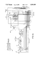
- FIG. 1 is a schematic diagram of this invention
- FIG. 2 is an absorption curve for Malachite, a commercial green dye, in aqueous solution.
- FIGS. 3 and 3a-3d are schematic diagrams of the computer and circuitry used in the present invention.
- FIGS. 1-3 The preferred embodiment and best mode of the invention is shown in FIGS. 1-3.
- a hand held colorimeter 10 is connected to a power source 11 such a batteries.
- the power source 11 is connected to a switching mechanism 12 which directs the current selectively through resistor 14 and/or resistor 16.
- resistors are placed in parallel to respective L.E.D. feed lines 18 and 22 and serve as current limiting resistors to prevent the L.E.D.'s from burning up.
- a red light emitting diode 24 is powered via line 22 and a green light emitting diode 20 is powered via line 18.
- the red L.E.D. would be automatically switched to green at a preselected glucose concentration. The less sensitive absorption would better serve more concentrated solutions. While the present invention uses red and green L.E.D.'s, it is within the scope of the invention to use other color light emitting diodes such as violet to determine various concentrations with varying degrees of accuracy.
- Both of the L.E.D.'s 20 and 24 are mounted in the optical chamber 30 to housing 26.
- a slot 27 is formed in housing 26 into which a chemically reacted test media such as strip 28 is placed.
- This strip 28 is positioned between the L.E.D.'s 20 and 24 and a photo transistor or photo Darlington 32 which is also positioned in the optical chamber 30 of the housing 26.
- One arm (cathode) of the photo transistor 32 leads to ground 34 and the other arm (anode) leads to C.P.U. 36 and pull up resistor 38 (R gain) to a voltage source not shown.
- the C.P.U. 36 receives a digital signal from an analog-to-digital converter which changes the analog signal received from the photo transistor into a digital number for readout and interpretation by the C.P.U. The higher the conductivity the greater voltage level.
- the L.E.D.'s pass a narrow band of spectral emission usually less than 5000 ⁇ and do not require filters.
- the intensity of the light does not vary with small voltage differences and consumes far less power than incandescent light.
- the incorporation of software to switch the light and calculations for concentration of substrate facilitate miniaturization and accuracy.
- the optical density is sensed by a broad range light sensitive diode which will respond to the emission spectra of all the L.E.D.'s.
- the L.E.D.'s can be switched at any preprogrammed optical density and the instructions for changing from one L.E.D. to another are contained in the computer software of the device.
- the chemical reactions can take place in a small cuvette, test tube or a paper or a plastic translucent, or a paper strip 28.
- a strip 28 the chemical reactants are present on the strip which is moistened with the solution containing the unknown concentration of the chemical to be measured.
- Indicators are chromophore which change color density and even spectra when the concentration of the test substance is changed.
- the green L.E.D. 20 is turned on if the voltage level from the phototransistor is 0 to 255.
- the red L.E.D. 24 is then turned on to expand the range of reading by combining the L.E.D.'s to get separate colors.
- L.E.D.'s 20 and 24 are connected via line 52 and 42 respectively to grounds 54 and 44, mosfet 46 and 56 and onto the C.P.U. through opto connector 58.
- the signal to the C.P.U. and associated circuitry 60 as shown in FIG. 3 begins executing a program which controls various routines relating to information obtained from the display strip 28.
- the operations circuitry 60 basically comprises a multiprocessor unit 62 Hitachi 63LO5 which has a C.P.U. on it and 4K of program storage and 96 bytes of RAM.
- the M.P.U. is connected to an eight bit analog-to-digital converter 64 which receives the current from photo transistor 32.
- the analog-to-digital converter has two timers, one of which is a second, time and day clock, the other providing interval time and is placed in a hold mode to limit power consumption.
- E prom 65 model number 27C512 uses 64 kilobytes with a low pass and high pass filter and stores the determined program for character transfer.
- a speech processor 71 model NEC7759 is connected to the E prom 65 and takes the speech characteristic from the digital storage of the E prom.
- An 8 byte addressable latch 73 with a 3 to 8 line decoder is connected to the speech processor and auxillary ram chip storage 76 which is used to store reading and time and date.
- Another 8 byte addressable latch 77 having the same construction as addressable latch 73 is connected to the printer connector 58 which is bidirectional ported.
- Chip 72 is an address and input chip known as a tristate output D-type latch.
- the program mask chip When the program mask chip is turned on, it checks the printer connector bank and if it senses ground, it checks to see if a printer or another computer is connected. If another computer is connected, the proram mask chip begins to communicate and loads a program into the ram of chip 76 which becomes program 6805 assembler.
- the program begins executing and this controls various applications such as the display strip readout and associated sub routines to give a number from 0 to 9, 10 to 1000 up to any four digit number in addition to listing various other subcommands such a service requirements, testing, strip acceptability, calibration, result in milliliters, concentration of sample in moles/liter, parts per million etc.
- the printing results are printed out from a three digit number.
Abstract
A method and apparatus for increasing the sensitivity and accuracy of apparatus used in chemical analysis utilizing the colorimeter method. The method employs two or more light emitting diodes which emit light at different wavelengths. The emission wavelength of the L.E.D. is automatically switched to an L.E.D. which most closely matches any desired absorption band in the solution being analyzed so that more or less absorption will occur in each range. A logic circuit which utilizes the initial optical density to choose the proper L.E.D. for the particular range of concentration of chromophore. Thus, a green emitting diode may be used to register an initial color change and automatically switched to a red L.E.D. at any chosen concentration.
Description
Colorimeters have employed white incandescent light and utilized color filters to select the proper color range for absorption. The choice of incandescent light is fraught with error because incandescent light is power consuming, varies greatly with small changes in voltage, and becomes less bright with time due to deposit of tungsten on the transparent quartz or glass transmitter.
Absorption spectroscopy both in the visible and infrared range has proved extremely valuable for the identification of compounds in solution. The limitations and usefulness of absorption spectroscopy has been covered in many texts eg.: Melon, Analytical Absorption Spectroscopy, John Wiley, NY 1950; Edisbury, Practical Hints on Absorption Spectroscopy, Plenum Press, 1968. The widespread use of absorption spectroscopy has lead to the publications of absorption spectra for almost all known compounds, eg.: Lang, L. Absorption Spectra in the Ultraviolet and Visible Region, Academic Press NY; Data for organic compounds can also be found in "Organic Electronic Spectral Data" by Phillips, Lyle & Jones Interscience Publishers NY. It thus becomes a simple matter to find the absorption spectra of any known substance or indicator. The indicators include those for oxidation-reduction (redox), pH and specific chemicals. When the absorption spectra is known, different frequencies on the absorption curve can be chosen and the proper L.E.D. selected so that the emission spectrum narrowly covers some selected frequency of the absorption spectra.
The absorption for Malachite, a commercial green dye, is maximum at 6000 Å in the orange-red range therefore the solution appears green. This color is the complimentary colors which is not absorbed.
A lesser secondary peak at 4000-4500 Å appears in the violet zone. Very dilute solutions would best be determined with a red or orange emitting L.E.D. to match the absorption peak at 6000 Å. Yet, high concentrations of malachite would be almost totally absorbed at this frequency. Therefore, it would be better to select a violet emitting diode if one wanted to determine high concentrations with less accuracy. If a red L.E.D. were used, dilute concentrations might be more exactly determined but at elevated concentrations the lesser absorption peak would be desirable and the emission spectra automatically switched.
In 1852, Beer observed that for any given thickness of a solution the transmittance of light of any specific wavelength depended exponentially on the concentration of the absorbing species. Thus if one were to plot transmittance against concentration for any specific substance at a specific wavelength, a linear relationship would exist between concentrations and transmittance and the plot would be a straight line. The slope of this straight line would be determined by the specific absorbance of the substance at the particular wavelength of the emitter. When the specific absorbance at one frequency is high, the slope, of the line is steep and with lower absorbance at a different frequency it would be more gradual. Obviously, if one wishes to accurately determine the substance at low concentrations the frequency with the steep slope is most desirable. If one wished to determine differences at high concentrations, a lower absorption peak would be preferable.
This problem of sensitivity for high and low ranges has previously been solved by having two different ranges on the same paper strip each with different color changes. This involves two independent circuits with two concentrations placed on the strip. Automatic switching to another L.E.D. better solves this problem without having to set two separate ranges on a single paper strip.
U.S. Pat. No. 3,994,590 to Di Martini et al. describes a colorimeter which employs a plurality of light emitting diodes to enable discrete frequency outputs. U.S. Pat. No. 4,566,797 to Kaffka et al. describes the use of two solid state radiation diodes or laser diodes, each of which emits a substantially monochromatic radiation at different wavelengths mounted in a cylinder used in connection with a spectrophotometer while U.S. Pat. No. 4,324,556 to Robertson et al. describes a spectrophotometer using a wave length selection filter to permit selection of a particular wave length emission. U.S. Pat. Nos. 4,319,884; 4,445,239; 4,445,239; 4,313,929; 4,305,664; 4,100,416 are generally concerned with use of selective wave length emissions in optical measuring devices.
A chemically impregnated strip is inserted into an optic chamber containing two or more different L.E.D.'s on one side and photo transistor on the other side of the strip. Light from the L.E.D. is transmitted across the strip to a phototransistor, which generates a signal to a computer and associated circuitry which is operated by software to give desired glucose concentration data.
For a more complete understanding of the invention, reference is made to the appended drawings in which:
FIG. 1 is a schematic diagram of this invention;
FIG. 2 is an absorption curve for Malachite, a commercial green dye, in aqueous solution; and
FIGS. 3 and 3a-3d are schematic diagrams of the computer and circuitry used in the present invention.
The preferred embodiment and best mode of the invention is shown in FIGS. 1-3. In the invention, a hand held colorimeter 10 is connected to a power source 11 such a batteries. The power source 11 is connected to a switching mechanism 12 which directs the current selectively through resistor 14 and/or resistor 16. These resistors are placed in parallel to respective L.E.D. feed lines 18 and 22 and serve as current limiting resistors to prevent the L.E.D.'s from burning up.
A red light emitting diode 24 is powered via line 22 and a green light emitting diode 20 is powered via line 18. The red L.E.D. would be automatically switched to green at a preselected glucose concentration. The less sensitive absorption would better serve more concentrated solutions. While the present invention uses red and green L.E.D.'s, it is within the scope of the invention to use other color light emitting diodes such as violet to determine various concentrations with varying degrees of accuracy.
Both of the L.E.D.'s 20 and 24 are mounted in the optical chamber 30 to housing 26. A slot 27 is formed in housing 26 into which a chemically reacted test media such as strip 28 is placed. This strip 28 is positioned between the L.E.D.'s 20 and 24 and a photo transistor or photo Darlington 32 which is also positioned in the optical chamber 30 of the housing 26. One arm (cathode) of the photo transistor 32 leads to ground 34 and the other arm (anode) leads to C.P.U. 36 and pull up resistor 38 (R gain) to a voltage source not shown. Thus, a current proportioned to an amount of light being received can be measured. The C.P.U. 36 receives a digital signal from an analog-to-digital converter which changes the analog signal received from the photo transistor into a digital number for readout and interpretation by the C.P.U. The higher the conductivity the greater voltage level.
The L.E.D.'s pass a narrow band of spectral emission usually less than 5000 Å and do not require filters. The intensity of the light does not vary with small voltage differences and consumes far less power than incandescent light. The incorporation of software to switch the light and calculations for concentration of substrate facilitate miniaturization and accuracy.
Many small battery operated hand held devices designated for the colorimeter determination of a single specific substance such as glucose, often contain a chromogenic indicator. A color changes in the indicator is then detected by increased light absorption of light from a light emitting diode. The concentration is sensed by a decrease in the transmission or reflection of light according to Beer and Lambert's Law. If a color change occurs in the chromogenic indicator, the narrow emission spectrum of L.E.D.'s may not suitably match some portions of the absorption spectrum of the chromophore. Therefore, greater sensitivity and accuracy could be achieved in the emission spectrum of the compound. This requires the activation of another L.E.D. with a different emission spectrum. The optical density is sensed by a broad range light sensitive diode which will respond to the emission spectra of all the L.E.D.'s. The L.E.D.'s can be switched at any preprogrammed optical density and the instructions for changing from one L.E.D. to another are contained in the computer software of the device.
The chemical reactions can take place in a small cuvette, test tube or a paper or a plastic translucent, or a paper strip 28. When using a strip 28 the chemical reactants are present on the strip which is moistened with the solution containing the unknown concentration of the chemical to be measured.
When white light is transmitted through a solution of a substance some wavelengths may be either absorbed or passed through the solution. For instance, malachite a commercial green dye absorbs all of other frequencies except green and therefore appears green. By transmitting white light through a solution of a substance and measuring the spectra of the transmitted light, the absorption spectra of the substance can be determined. Indicators are chromophore which change color density and even spectra when the concentration of the test substance is changed.
Thus, the green L.E.D. 20 is turned on if the voltage level from the phototransistor is 0 to 255. The red L.E.D. 24 is then turned on to expand the range of reading by combining the L.E.D.'s to get separate colors.
L.E.D.'s 20 and 24 are connected via line 52 and 42 respectively to grounds 54 and 44, mosfet 46 and 56 and onto the C.P.U. through opto connector 58.
The signal to the C.P.U. and associated circuitry 60 as shown in FIG. 3 begins executing a program which controls various routines relating to information obtained from the display strip 28. The operations circuitry 60 basically comprises a multiprocessor unit 62 Hitachi 63LO5 which has a C.P.U. on it and 4K of program storage and 96 bytes of RAM. The M.P.U. is connected to an eight bit analog-to-digital converter 64 which receives the current from photo transistor 32. The analog-to-digital converter has two timers, one of which is a second, time and day clock, the other providing interval time and is placed in a hold mode to limit power consumption. E prom 65 model number 27C512 uses 64 kilobytes with a low pass and high pass filter and stores the determined program for character transfer. A speech processor 71 model NEC7759 is connected to the E prom 65 and takes the speech characteristic from the digital storage of the E prom. An 8 byte addressable latch 73 with a 3 to 8 line decoder is connected to the speech processor and auxillary ram chip storage 76 which is used to store reading and time and date. Another 8 byte addressable latch 77 having the same construction as addressable latch 73 is connected to the printer connector 58 which is bidirectional ported. Chip 72 is an address and input chip known as a tristate output D-type latch. When the program mask chip is turned on, it checks the printer connector bank and if it senses ground, it checks to see if a printer or another computer is connected. If another computer is connected, the proram mask chip begins to communicate and loads a program into the ram of chip 76 which becomes program 6805 assembler.
The program begins executing and this controls various applications such as the display strip readout and associated sub routines to give a number from 0 to 9, 10 to 1000 up to any four digit number in addition to listing various other subcommands such a service requirements, testing, strip acceptability, calibration, result in milliliters, concentration of sample in moles/liter, parts per million etc. The printing results are printed out from a three digit number.
It can thus been seen that the present invention and inventive system provides rapid and convenient access to information of a visual nature taken from optical readings of a chemically treated strip which permits identification by color wavelength to determine various data components and provide medical information. The following is a listing of the control program for the computer which implements the process of the present invention in the hardware combination described above. ##SPC1##
While a presently preferred form of the present invention has been set forth hereinabove, it is to be understood that the invention is not limited thereby and in particular the steps of the inventive process are interchangeable, may be interchanged and are equivalent. It is to be understood that the specific details shown are merely illustrative and that the invention may be carried out in other ways without departing from the true spirit and scope of the following claims.
Claims (8)
1. A process of operating a glucose monitoring system comprising the steps of
(a) selectively energizing one of a plurality of different color light emitting diodes to emit light against a test specimen strip with a glucose concentration falling within a range of differing glucose concentrations causing differing absorption spectra;
(b) receiving conductive emissions from a selected diode through said test specimen strip with photo transistor means and converting the emissions with said photo transistor means into an electronic signal;
(c) transmitting said electronic signal to a computer;
(d) providing said computer with a characteristic data base comprising a plurality of records corresponding to each of a number of readout components, each of said records comprising a plurality of characteristic identifiers describing corresponding specimens and including at least characteristics in the categories of milliliters per deciliter, four digit number readout, acceptability indicator; and
(e) displaying said characteristics.
2. The process as claimed in claim 1 wherein said characteristics which are displayed in step (e) are displayed by a printer.
3. The process as claimed in claim 1 wherein said characteristics which are displayed in step (e) are displayed by a speech synthesizer means.
4. The process as claimed in claim 1 wherein said characteristics which are displayed in step (e) are displayed by a CRT.
5. An apparatus for measuring chemical concentration on a media comprising;
a housing, means in said housing for receiving a test media strip having an unknown concentration of test sample, a plurality of different monochromatic light emitting diodes mounted in said housing and connected to a power source, said light emitting diodes being adapted to be selectively powered at a preselected test sample concentration to transmit light through said test media strip with concentration of test sample, photo transistor means mounted in said housing, said photo transistor means being adapted to receive light from a specifically selected light emitting diode selected from said plurality of light emitting diodes which passes through said test media strip with test sample and transmit current proportional to an amount of light being received to an analog-to-digital converter, said analog-to-digital converter producing a digital signal and being connected to computer means which receives the digital signal and transmits selected information about the test sample concentration on the test media strip.
6. An apparatus for measuring chemical concentration as claimed in claim 5 wherein said light emitting diodes are red and green and are selectively powered by a power source and said apparatus includes switching means which switches the power source from the red light emitting diode to the green emitting diode at a preselected sample concentration sensed by a decrease in the transmission of light.
7. An apparatus as claimed in claim 5 wherein said selected information is transmitted to measurement and read out means for converting the signal to a read out indicative of at least one of either the absorbence or transmission of said test media strip with sample with respect to the wavelength of said monochromatic light reflecting a color change in a chromogenic indicator on said test media strip.
8. An apparatus as claimed in claim 5 wherein said sample is glucose.
Priority Applications (1)
| Application Number | Priority Date | Filing Date | Title |
|---|---|---|---|
| US07/176,331 US4949400A (en) | 1988-03-31 | 1988-03-31 | Hand held glucose colorimeter device |
Applications Claiming Priority (1)
| Application Number | Priority Date | Filing Date | Title |
|---|---|---|---|
| US07/176,331 US4949400A (en) | 1988-03-31 | 1988-03-31 | Hand held glucose colorimeter device |
Publications (1)
| Publication Number | Publication Date |
|---|---|
| US4949400A true US4949400A (en) | 1990-08-14 |
Family
ID=22643931
Family Applications (1)
| Application Number | Title | Priority Date | Filing Date |
|---|---|---|---|
| US07/176,331 Expired - Fee Related US4949400A (en) | 1988-03-31 | 1988-03-31 | Hand held glucose colorimeter device |
Country Status (1)
| Country | Link |
|---|---|
| US (1) | US4949400A (en) |
Cited By (12)
| Publication number | Priority date | Publication date | Assignee | Title |
|---|---|---|---|---|
| US5298224A (en) * | 1988-01-14 | 1994-03-29 | Novo Nordisk A/S | Apparatus for determination of the coagulation time of a blood sample |
| US5618495A (en) * | 1993-07-26 | 1997-04-08 | Mount; Andrew S. | Colorimetric titration method and apparatus |
| US5728352A (en) * | 1994-11-14 | 1998-03-17 | Advanced Care Products | Disposable electronic diagnostic instrument |
| US5963333A (en) * | 1996-09-12 | 1999-10-05 | Color Savvy Systems Limited | Color sensor |
| US5968760A (en) * | 1986-08-13 | 1999-10-19 | Lifescan, Inc. | Temperature-Independent Blood Glucose Measurement |
| GB2352511A (en) * | 1999-07-23 | 2001-01-31 | Univ Bath | Colorimeter having an LED light source |
| US6304327B1 (en) * | 1999-03-02 | 2001-10-16 | Vulcan Chemicals | Method and apparatus for photometric analysis of chlorine dioxide solutions |
| US6369895B1 (en) | 2000-02-16 | 2002-04-09 | Electronics For Imaging, Inc. | Color measurement instrument with asymmetric tapered sample area optical enclosure |
| US6458326B1 (en) | 1999-11-24 | 2002-10-01 | Home Diagnostics, Inc. | Protective test strip platform |
| US6525330B2 (en) | 2001-02-28 | 2003-02-25 | Home Diagnostics, Inc. | Method of strip insertion detection |
| US6541266B2 (en) | 2001-02-28 | 2003-04-01 | Home Diagnostics, Inc. | Method for determining concentration of an analyte in a test strip |
| US20120086942A1 (en) * | 2009-06-23 | 2012-04-12 | National University Corporation University Of Fukui | Oil state monitoring method and oil state monitoring device |
Citations (4)
| Publication number | Priority date | Publication date | Assignee | Title |
|---|---|---|---|---|
| US2554414A (en) * | 1945-07-12 | 1951-05-22 | Phillips Petroleum Co | Apparatus for determining a chemically reactive gas |
| US4552458A (en) * | 1983-10-11 | 1985-11-12 | Eastman Kodak Company | Compact reflectometer |
| US4637403A (en) * | 1985-04-08 | 1987-01-20 | Garid, Inc. | Glucose medical monitoring system |
| US4755058A (en) * | 1984-06-19 | 1988-07-05 | Miles Laboratories, Inc. | Device and method for measuring light diffusely reflected from a nonuniform specimen |
-
1988
- 1988-03-31 US US07/176,331 patent/US4949400A/en not_active Expired - Fee Related
Patent Citations (4)
| Publication number | Priority date | Publication date | Assignee | Title |
|---|---|---|---|---|
| US2554414A (en) * | 1945-07-12 | 1951-05-22 | Phillips Petroleum Co | Apparatus for determining a chemically reactive gas |
| US4552458A (en) * | 1983-10-11 | 1985-11-12 | Eastman Kodak Company | Compact reflectometer |
| US4755058A (en) * | 1984-06-19 | 1988-07-05 | Miles Laboratories, Inc. | Device and method for measuring light diffusely reflected from a nonuniform specimen |
| US4637403A (en) * | 1985-04-08 | 1987-01-20 | Garid, Inc. | Glucose medical monitoring system |
Cited By (18)
| Publication number | Priority date | Publication date | Assignee | Title |
|---|---|---|---|---|
| US6268162B1 (en) | 1986-08-13 | 2001-07-31 | Lifescan, Inc. | Reflectance measurement of analyte concentration with automatic initiation of timing |
| US5968760A (en) * | 1986-08-13 | 1999-10-19 | Lifescan, Inc. | Temperature-Independent Blood Glucose Measurement |
| US6821483B2 (en) | 1986-08-13 | 2004-11-23 | Lifescan, Inc. | Reagents test strip with alignment notch |
| US5298224A (en) * | 1988-01-14 | 1994-03-29 | Novo Nordisk A/S | Apparatus for determination of the coagulation time of a blood sample |
| US5618495A (en) * | 1993-07-26 | 1997-04-08 | Mount; Andrew S. | Colorimetric titration method and apparatus |
| US5728352A (en) * | 1994-11-14 | 1998-03-17 | Advanced Care Products | Disposable electronic diagnostic instrument |
| US5795543A (en) * | 1994-11-14 | 1998-08-18 | Advanced Care Products | Disposable electronic diagnostic instrument |
| US5963333A (en) * | 1996-09-12 | 1999-10-05 | Color Savvy Systems Limited | Color sensor |
| US6020583A (en) * | 1996-09-12 | 2000-02-01 | Color Savvy Systems Limited | Color sensor |
| US6304327B1 (en) * | 1999-03-02 | 2001-10-16 | Vulcan Chemicals | Method and apparatus for photometric analysis of chlorine dioxide solutions |
| GB2352511A (en) * | 1999-07-23 | 2001-01-31 | Univ Bath | Colorimeter having an LED light source |
| GB2352511B (en) * | 1999-07-23 | 2004-05-12 | Univ Bath | Colourimetry device |
| US6458326B1 (en) | 1999-11-24 | 2002-10-01 | Home Diagnostics, Inc. | Protective test strip platform |
| US6369895B1 (en) | 2000-02-16 | 2002-04-09 | Electronics For Imaging, Inc. | Color measurement instrument with asymmetric tapered sample area optical enclosure |
| US6525330B2 (en) | 2001-02-28 | 2003-02-25 | Home Diagnostics, Inc. | Method of strip insertion detection |
| US6541266B2 (en) | 2001-02-28 | 2003-04-01 | Home Diagnostics, Inc. | Method for determining concentration of an analyte in a test strip |
| US20120086942A1 (en) * | 2009-06-23 | 2012-04-12 | National University Corporation University Of Fukui | Oil state monitoring method and oil state monitoring device |
| US8390796B2 (en) * | 2009-06-23 | 2013-03-05 | National University Corporation University Of Fukui | Oil state monitoring method and oil state monitoring device |
Similar Documents
| Publication | Publication Date | Title |
|---|---|---|
| CA1078641A (en) | Pulsed light colorimeter | |
| US5618495A (en) | Colorimetric titration method and apparatus | |
| US4949400A (en) | Hand held glucose colorimeter device | |
| US20100167412A1 (en) | Sensor system for determining concentration of chemical and biological analytes | |
| CN1961205B (en) | Handheld device with a disposable element for chemical analysis of multiple analytes | |
| Lippitsch et al. | Fibre-optic oxygen sensor with the fluorescence decay time as the information carrier | |
| EP0026885A1 (en) | Filterphotometer | |
| JPH0815016A (en) | Reading head of multiple detector for photometer | |
| EP0515526A1 (en) | Multisource device for photometric analysis and associated chromogens | |
| Hauser et al. | All-solid-state instrument for fluorescence-based fibre-optic chemical sensors | |
| AU738290B2 (en) | Method and apparatus for determining characteristics of a sample in the presence of ambient light | |
| US4921351A (en) | Spectrophotometer comprising a xenon flashtube as a light source | |
| US7046347B1 (en) | Instrument with colorimeter and sensor inputs for interfacing with a computer | |
| Burgess et al. | Advances in standards and methodology in spectrophotometry | |
| US5708275A (en) | PH measurement utilizing a light source | |
| Grattan et al. | Dual wavelength optical fibre sensor for pH measurement | |
| CN212780522U (en) | Portable water quality analyzer for soluble organic matters and turbidity | |
| Lefar et al. | Thin layer densitometry | |
| JP2894364B2 (en) | Optical measuring device | |
| Jones et al. | A field-deployable dual-wavelength fiber-optic pH sensor instrument based on solid-state optical and electrical components | |
| US6016192A (en) | External calibration system for a photo multiplier tube | |
| US3656856A (en) | Colorimeter | |
| JP2001108621A (en) | Ion optode and ion optode meter | |
| Renoe et al. | A versatile minidisc module for a centrifugal analyzer | |
| US3690773A (en) | Dual photoconductive cell photometer |
Legal Events
| Date | Code | Title | Description |
|---|---|---|---|
| REMI | Maintenance fee reminder mailed | ||
| LAPS | Lapse for failure to pay maintenance fees | ||
| FP | Expired due to failure to pay maintenance fee |
Effective date: 19940817 |
|
| STCH | Information on status: patent discontinuation |
Free format text: PATENT EXPIRED DUE TO NONPAYMENT OF MAINTENANCE FEES UNDER 37 CFR 1.362 |