US4944072A - Profiled fasteners - Google Patents
Profiled fasteners Download PDFInfo
- Publication number
- US4944072A US4944072A US07/368,775 US36877589A US4944072A US 4944072 A US4944072 A US 4944072A US 36877589 A US36877589 A US 36877589A US 4944072 A US4944072 A US 4944072A
- Authority
- US
- United States
- Prior art keywords
- bead
- recess
- fastener
- section
- entrance
- Prior art date
- Legal status (The legal status is an assumption and is not a legal conclusion. Google has not performed a legal analysis and makes no representation as to the accuracy of the status listed.)
- Expired - Lifetime
Links
- 239000011324 bead Substances 0.000 claims abstract description 166
- 230000013011 mating Effects 0.000 claims abstract description 15
- 230000000295 complement effect Effects 0.000 claims abstract description 8
- 239000000463 material Substances 0.000 claims description 19
- 239000004753 textile Substances 0.000 claims description 15
- 230000000694 effects Effects 0.000 claims description 13
- 230000005489 elastic deformation Effects 0.000 claims description 11
- 238000009958 sewing Methods 0.000 claims description 11
- 239000011435 rock Substances 0.000 claims description 8
- 230000000750 progressive effect Effects 0.000 claims description 6
- 238000000926 separation method Methods 0.000 abstract description 2
- 239000004033 plastic Substances 0.000 description 7
- 229920003023 plastic Polymers 0.000 description 7
- 238000001125 extrusion Methods 0.000 description 6
- 239000000853 adhesive Substances 0.000 description 3
- 230000001070 adhesive effect Effects 0.000 description 3
- 238000005452 bending Methods 0.000 description 2
- 238000003780 insertion Methods 0.000 description 2
- 230000037431 insertion Effects 0.000 description 2
- 230000035515 penetration Effects 0.000 description 2
- 229920000728 polyester Polymers 0.000 description 2
- -1 polypropylene Polymers 0.000 description 2
- 230000011218 segmentation Effects 0.000 description 2
- 241000251730 Chondrichthyes Species 0.000 description 1
- 239000004677 Nylon Substances 0.000 description 1
- 239000004952 Polyamide Substances 0.000 description 1
- 239000004743 Polypropylene Substances 0.000 description 1
- 230000002159 abnormal effect Effects 0.000 description 1
- 239000004411 aluminium Substances 0.000 description 1
- 229910052782 aluminium Inorganic materials 0.000 description 1
- XAGFODPZIPBFFR-UHFFFAOYSA-N aluminium Chemical compound [Al] XAGFODPZIPBFFR-UHFFFAOYSA-N 0.000 description 1
- 230000001419 dependent effect Effects 0.000 description 1
- 230000000881 depressing effect Effects 0.000 description 1
- 230000000994 depressogenic effect Effects 0.000 description 1
- 229910052751 metal Inorganic materials 0.000 description 1
- 239000002184 metal Substances 0.000 description 1
- 238000000465 moulding Methods 0.000 description 1
- 229920001778 nylon Polymers 0.000 description 1
- 230000002093 peripheral effect Effects 0.000 description 1
- 229920002647 polyamide Polymers 0.000 description 1
- 229920000642 polymer Polymers 0.000 description 1
- 229920001155 polypropylene Polymers 0.000 description 1
- 238000005096 rolling process Methods 0.000 description 1
- 239000000565 sealant Substances 0.000 description 1
- 238000003466 welding Methods 0.000 description 1
Images


Classifications
-
- B—PERFORMING OPERATIONS; TRANSPORTING
- B65—CONVEYING; PACKING; STORING; HANDLING THIN OR FILAMENTARY MATERIAL
- B65D—CONTAINERS FOR STORAGE OR TRANSPORT OF ARTICLES OR MATERIALS, e.g. BAGS, BARRELS, BOTTLES, BOXES, CANS, CARTONS, CRATES, DRUMS, JARS, TANKS, HOPPERS, FORWARDING CONTAINERS; ACCESSORIES, CLOSURES, OR FITTINGS THEREFOR; PACKAGING ELEMENTS; PACKAGES
- B65D43/00—Lids or covers for rigid or semi-rigid containers
- B65D43/02—Removable lids or covers
- B65D43/0202—Removable lids or covers without integral tamper element
- B65D43/0204—Removable lids or covers without integral tamper element secured by snapping over beads or projections
- B65D43/0206—Removable lids or covers without integral tamper element secured by snapping over beads or projections inside a peripheral U-shaped channel in the mouth of the container
-
- A—HUMAN NECESSITIES
- A44—HABERDASHERY; JEWELLERY
- A44B—BUTTONS, PINS, BUCKLES, SLIDE FASTENERS, OR THE LIKE
- A44B19/00—Slide fasteners
- A44B19/10—Slide fasteners with a one-piece interlocking member on each stringer tape
- A44B19/16—Interlocking member having uniform section throughout the length of the stringer
-
- F—MECHANICAL ENGINEERING; LIGHTING; HEATING; WEAPONS; BLASTING
- F16—ENGINEERING ELEMENTS AND UNITS; GENERAL MEASURES FOR PRODUCING AND MAINTAINING EFFECTIVE FUNCTIONING OF MACHINES OR INSTALLATIONS; THERMAL INSULATION IN GENERAL
- F16B—DEVICES FOR FASTENING OR SECURING CONSTRUCTIONAL ELEMENTS OR MACHINE PARTS TOGETHER, e.g. NAILS, BOLTS, CIRCLIPS, CLAMPS, CLIPS OR WEDGES; JOINTS OR JOINTING
- F16B5/00—Joining sheets or plates, e.g. panels, to one another or to strips or bars parallel to them
- F16B5/07—Joining sheets or plates, e.g. panels, to one another or to strips or bars parallel to them by means of multiple interengaging protrusions on the surfaces, e.g. hooks, coils
-
- B—PERFORMING OPERATIONS; TRANSPORTING
- B65—CONVEYING; PACKING; STORING; HANDLING THIN OR FILAMENTARY MATERIAL
- B65D—CONTAINERS FOR STORAGE OR TRANSPORT OF ARTICLES OR MATERIALS, e.g. BAGS, BARRELS, BOTTLES, BOXES, CANS, CARTONS, CRATES, DRUMS, JARS, TANKS, HOPPERS, FORWARDING CONTAINERS; ACCESSORIES, CLOSURES, OR FITTINGS THEREFOR; PACKAGING ELEMENTS; PACKAGES
- B65D2543/00—Lids or covers essentially for box-like containers
- B65D2543/00009—Details of lids or covers for rigid or semi-rigid containers
- B65D2543/00018—Overall construction of the lid
- B65D2543/00064—Shape of the outer periphery
- B65D2543/00074—Shape of the outer periphery curved
- B65D2543/00092—Shape of the outer periphery curved circular
-
- B—PERFORMING OPERATIONS; TRANSPORTING
- B65—CONVEYING; PACKING; STORING; HANDLING THIN OR FILAMENTARY MATERIAL
- B65D—CONTAINERS FOR STORAGE OR TRANSPORT OF ARTICLES OR MATERIALS, e.g. BAGS, BARRELS, BOTTLES, BOXES, CANS, CARTONS, CRATES, DRUMS, JARS, TANKS, HOPPERS, FORWARDING CONTAINERS; ACCESSORIES, CLOSURES, OR FITTINGS THEREFOR; PACKAGING ELEMENTS; PACKAGES
- B65D2543/00—Lids or covers essentially for box-like containers
- B65D2543/00009—Details of lids or covers for rigid or semi-rigid containers
- B65D2543/00018—Overall construction of the lid
- B65D2543/00259—Materials used
- B65D2543/00296—Plastic
-
- B—PERFORMING OPERATIONS; TRANSPORTING
- B65—CONVEYING; PACKING; STORING; HANDLING THIN OR FILAMENTARY MATERIAL
- B65D—CONTAINERS FOR STORAGE OR TRANSPORT OF ARTICLES OR MATERIALS, e.g. BAGS, BARRELS, BOTTLES, BOXES, CANS, CARTONS, CRATES, DRUMS, JARS, TANKS, HOPPERS, FORWARDING CONTAINERS; ACCESSORIES, CLOSURES, OR FITTINGS THEREFOR; PACKAGING ELEMENTS; PACKAGES
- B65D2543/00—Lids or covers essentially for box-like containers
- B65D2543/00009—Details of lids or covers for rigid or semi-rigid containers
- B65D2543/00444—Contact between the container and the lid
- B65D2543/00453—Contact between the container and the lid in a peripheral U-shaped channel of the container
- B65D2543/00472—Skirt
-
- B—PERFORMING OPERATIONS; TRANSPORTING
- B65—CONVEYING; PACKING; STORING; HANDLING THIN OR FILAMENTARY MATERIAL
- B65D—CONTAINERS FOR STORAGE OR TRANSPORT OF ARTICLES OR MATERIALS, e.g. BAGS, BARRELS, BOTTLES, BOXES, CANS, CARTONS, CRATES, DRUMS, JARS, TANKS, HOPPERS, FORWARDING CONTAINERS; ACCESSORIES, CLOSURES, OR FITTINGS THEREFOR; PACKAGING ELEMENTS; PACKAGES
- B65D2543/00—Lids or covers essentially for box-like containers
- B65D2543/00009—Details of lids or covers for rigid or semi-rigid containers
- B65D2543/00444—Contact between the container and the lid
- B65D2543/00481—Contact between the container and the lid on the inside or the outside of the container
- B65D2543/0049—Contact between the container and the lid on the inside or the outside of the container on the inside, or a part turned to the inside of the mouth of the container
- B65D2543/00518—Skirt
-
- B—PERFORMING OPERATIONS; TRANSPORTING
- B65—CONVEYING; PACKING; STORING; HANDLING THIN OR FILAMENTARY MATERIAL
- B65D—CONTAINERS FOR STORAGE OR TRANSPORT OF ARTICLES OR MATERIALS, e.g. BAGS, BARRELS, BOTTLES, BOXES, CANS, CARTONS, CRATES, DRUMS, JARS, TANKS, HOPPERS, FORWARDING CONTAINERS; ACCESSORIES, CLOSURES, OR FITTINGS THEREFOR; PACKAGING ELEMENTS; PACKAGES
- B65D2543/00—Lids or covers essentially for box-like containers
- B65D2543/00009—Details of lids or covers for rigid or semi-rigid containers
- B65D2543/00444—Contact between the container and the lid
- B65D2543/00481—Contact between the container and the lid on the inside or the outside of the container
- B65D2543/00537—Contact between the container and the lid on the inside or the outside of the container on the outside, or a part turned to the outside of the mouth of the container
- B65D2543/00546—NO contact
-
- B—PERFORMING OPERATIONS; TRANSPORTING
- B65—CONVEYING; PACKING; STORING; HANDLING THIN OR FILAMENTARY MATERIAL
- B65D—CONTAINERS FOR STORAGE OR TRANSPORT OF ARTICLES OR MATERIALS, e.g. BAGS, BARRELS, BOTTLES, BOXES, CANS, CARTONS, CRATES, DRUMS, JARS, TANKS, HOPPERS, FORWARDING CONTAINERS; ACCESSORIES, CLOSURES, OR FITTINGS THEREFOR; PACKAGING ELEMENTS; PACKAGES
- B65D2543/00—Lids or covers essentially for box-like containers
- B65D2543/00009—Details of lids or covers for rigid or semi-rigid containers
- B65D2543/00444—Contact between the container and the lid
- B65D2543/00592—Snapping means
- B65D2543/00601—Snapping means on the container
- B65D2543/00611—Profiles
- B65D2543/00629—Massive bead
-
- B—PERFORMING OPERATIONS; TRANSPORTING
- B65—CONVEYING; PACKING; STORING; HANDLING THIN OR FILAMENTARY MATERIAL
- B65D—CONTAINERS FOR STORAGE OR TRANSPORT OF ARTICLES OR MATERIALS, e.g. BAGS, BARRELS, BOTTLES, BOXES, CANS, CARTONS, CRATES, DRUMS, JARS, TANKS, HOPPERS, FORWARDING CONTAINERS; ACCESSORIES, CLOSURES, OR FITTINGS THEREFOR; PACKAGING ELEMENTS; PACKAGES
- B65D2543/00—Lids or covers essentially for box-like containers
- B65D2543/00009—Details of lids or covers for rigid or semi-rigid containers
- B65D2543/00444—Contact between the container and the lid
- B65D2543/00592—Snapping means
- B65D2543/00601—Snapping means on the container
- B65D2543/00675—Periphery concerned
- B65D2543/00685—Totality
-
- B—PERFORMING OPERATIONS; TRANSPORTING
- B65—CONVEYING; PACKING; STORING; HANDLING THIN OR FILAMENTARY MATERIAL
- B65D—CONTAINERS FOR STORAGE OR TRANSPORT OF ARTICLES OR MATERIALS, e.g. BAGS, BARRELS, BOTTLES, BOXES, CANS, CARTONS, CRATES, DRUMS, JARS, TANKS, HOPPERS, FORWARDING CONTAINERS; ACCESSORIES, CLOSURES, OR FITTINGS THEREFOR; PACKAGING ELEMENTS; PACKAGES
- B65D2543/00—Lids or covers essentially for box-like containers
- B65D2543/00009—Details of lids or covers for rigid or semi-rigid containers
- B65D2543/00444—Contact between the container and the lid
- B65D2543/00592—Snapping means
- B65D2543/00712—Snapping means on the lid
- B65D2543/00722—Profiles
- B65D2543/0074—Massive bead
-
- B—PERFORMING OPERATIONS; TRANSPORTING
- B65—CONVEYING; PACKING; STORING; HANDLING THIN OR FILAMENTARY MATERIAL
- B65D—CONTAINERS FOR STORAGE OR TRANSPORT OF ARTICLES OR MATERIALS, e.g. BAGS, BARRELS, BOTTLES, BOXES, CANS, CARTONS, CRATES, DRUMS, JARS, TANKS, HOPPERS, FORWARDING CONTAINERS; ACCESSORIES, CLOSURES, OR FITTINGS THEREFOR; PACKAGING ELEMENTS; PACKAGES
- B65D2543/00—Lids or covers essentially for box-like containers
- B65D2543/00009—Details of lids or covers for rigid or semi-rigid containers
- B65D2543/00444—Contact between the container and the lid
- B65D2543/00592—Snapping means
- B65D2543/00712—Snapping means on the lid
- B65D2543/00787—Periphery concerned
- B65D2543/00796—Totality
-
- B—PERFORMING OPERATIONS; TRANSPORTING
- B65—CONVEYING; PACKING; STORING; HANDLING THIN OR FILAMENTARY MATERIAL
- B65D—CONTAINERS FOR STORAGE OR TRANSPORT OF ARTICLES OR MATERIALS, e.g. BAGS, BARRELS, BOTTLES, BOXES, CANS, CARTONS, CRATES, DRUMS, JARS, TANKS, HOPPERS, FORWARDING CONTAINERS; ACCESSORIES, CLOSURES, OR FITTINGS THEREFOR; PACKAGING ELEMENTS; PACKAGES
- B65D2543/00—Lids or covers essentially for box-like containers
- B65D2543/00009—Details of lids or covers for rigid or semi-rigid containers
- B65D2543/00824—Means for facilitating removing of the closure
- B65D2543/00833—Integral tabs, tongues, handles or similar
- B65D2543/00842—Integral tabs, tongues, handles or similar outside of the lid
-
- Y—GENERAL TAGGING OF NEW TECHNOLOGICAL DEVELOPMENTS; GENERAL TAGGING OF CROSS-SECTIONAL TECHNOLOGIES SPANNING OVER SEVERAL SECTIONS OF THE IPC; TECHNICAL SUBJECTS COVERED BY FORMER USPC CROSS-REFERENCE ART COLLECTIONS [XRACs] AND DIGESTS
- Y10—TECHNICAL SUBJECTS COVERED BY FORMER USPC
- Y10S—TECHNICAL SUBJECTS COVERED BY FORMER USPC CROSS-REFERENCE ART COLLECTIONS [XRACs] AND DIGESTS
- Y10S24/00—Buckles, buttons, clasps
- Y10S24/30—Separable-fastener or required component thereof
- Y10S24/38—Each mating member having similarly shaped, sized, and operated interlocking face
- Y10S24/39—Each mating member having similarly shaped, sized, and operated interlocking face including elongated face having identical, parallel cross sections throughout its length
-
- Y—GENERAL TAGGING OF NEW TECHNOLOGICAL DEVELOPMENTS; GENERAL TAGGING OF CROSS-SECTIONAL TECHNOLOGIES SPANNING OVER SEVERAL SECTIONS OF THE IPC; TECHNICAL SUBJECTS COVERED BY FORMER USPC CROSS-REFERENCE ART COLLECTIONS [XRACs] AND DIGESTS
- Y10—TECHNICAL SUBJECTS COVERED BY FORMER USPC
- Y10S—TECHNICAL SUBJECTS COVERED BY FORMER USPC CROSS-REFERENCE ART COLLECTIONS [XRACs] AND DIGESTS
- Y10S24/00—Buckles, buttons, clasps
- Y10S24/30—Separable-fastener or required component thereof
- Y10S24/50—Separable-fastener or required component thereof including member having elongated, resilient, interlocking face with identical, parallel cross-sections throughout its length
-
- Y—GENERAL TAGGING OF NEW TECHNOLOGICAL DEVELOPMENTS; GENERAL TAGGING OF CROSS-SECTIONAL TECHNOLOGIES SPANNING OVER SEVERAL SECTIONS OF THE IPC; TECHNICAL SUBJECTS COVERED BY FORMER USPC CROSS-REFERENCE ART COLLECTIONS [XRACs] AND DIGESTS
- Y10—TECHNICAL SUBJECTS COVERED BY FORMER USPC
- Y10T—TECHNICAL SUBJECTS COVERED BY FORMER US CLASSIFICATION
- Y10T24/00—Buckles, buttons, clasps, etc.
- Y10T24/45—Separable-fastener or required component thereof [e.g., projection and cavity to complete interlock]
- Y10T24/45152—Each mating member having similarly shaped, sized, and operated interlocking or intermeshable face
- Y10T24/45157—Zipper-type [e.g., slider]
- Y10T24/45168—Zipper-type [e.g., slider] for container [e.g., bag]
Definitions
- This invention relates to profiled, bead and recess fasteners, such as may be made by extrusion of plastics material to substitute for the slide type fastener with interlocking teeth attached to stringers that can be sewn to edges e.g. of garments required to be releasably joined.
- profiled fasteners are to be found on plastic document wallets.
- the present invention provides an improved fastener which can be made adequately secure against unintended springing open and one which can be opened and closed without the need for a slider, although a slider might be provided while retaining the other improvements.
- the invention comprises a profiled bead and recess fastener comprising mating, complementary parts of which one part has a recess and the other part has a bead which engages in the recess to maintain the fastener closed against tension forces so directed as to tend to separate the two parts, the recess having, in cross section, an entrance for the bead, which is smaller in cross section than the bead cross section whereby to retain the bead in the recess, the cross section of said entrance being adjustable by local elastic deformation to permit the bead to enter or leave the recess laterally, such deformation comprising flexure of one side of the recess by the bead whilst the bead comes out of contact with the other side of the recess.
- Such flexure may be effected by finger pressure on the bead part. Said finger pressure may cause the bead part to rock on the recess part to press the bead against the said one side of the recess.
- Said bead part may comprise a lever which rocks on the recess part and carries the bead, such rocking urging the bead against said one side of the recess and out of contact with the other side of the recess whereby to adjust the cross section of the entrance so that the bead can be withdrawn, continued rocking then withdrawing the bead from the recess.
- Said lever may have a lever arm adapted to be pushed by finger pressure towards the recess part to effect the rocking which opens the entrance to the recess.
- Said lever may otherwise, or in addition, have a lever arm adapted to be lifted by finger pressure away from the recess part to effect the rocking which opens the entrance to the recess.
- Said finger pressure may cause the bead part to slide on the recess part, however, to press the bead against the said one side of the recess.
- the bead and entrance to the recess may be so shaped that pushing the bead towards the recess against the said entrance opens the entrance to admit the bead.
- At least parts which move over each other in the actions of opening and closing may have low friction.
- the fastener may be an elongate, flexible fastener with a continuous, uniform cross section, opening of which, after a start thereon by said recess deformation, is continued progresssively by pulling the two parts apart, the bead at the position where the fastener is half open holding open the entrance to the recess whereby the next adjacent bead portion can be pulled out.
- the fastener may, however, be an elongate flexible fastener which is segmented lengthwise so that the opening of any segment does not open the entrance of an adjacent segment sufficiently to allow the bead therein to come out.
- the fastener may be segmented lengthwise by notches or by inclusions of reduced-modulus material.
- a fastener may have at least one lengthwise section at any part of which local elastic deformation to permit the bead to leave the recess laterally cannot be effected except by, at an adjacent part, the bead holding open the entrance to the recess, so that opening of the fastener cannot be started within said section.
- the fastener may be made by extrusion, especially by extruding a plastics material which may then be drawn after extrusion.
- the fastener may be co-extruded from different materials as, for example, from regular and low friction and/or low modulus/high modulus materials so as to arrange for desired frictional/flexural properties at different parts of the cross section.
- the fastener may be intended for use as a closure for textiles, having attachment edges, one on each of said parts, for connecting to textiles.
- the fastener may be adapted for sewing to textiles by the attachment edges being adapted for needle penetration, and being of reasonable strength, possibly being reinforced with textile thread or ribbon, and may have a sewing guide by which machine sewing is facilitated.
- the attachment edges may also be profiled to accept and grip a textile selvedge, and they may be adhesive.
- An elongate fastener may have at least one closed end.
- a fastener may have two or more recesses and/or two or more beads, which bead or any one of which beads can be engaged in the recess or any one of the recesses, whereby to produce an adjustable width fastening.
- the fastener may comprise auxiliary bead and recess means assisting in maintaining the fastener closed under tension forces but separable together with the first mentioned bead coming out of its recess.
- Said auxiliary bead and recess means may be readily engageable and form pilot engagement means facilitating engaging the first mentioned bead with its recess.
- the fastener may be fashioned as a sliderless elongate fastener, it may also be realised as a slider fastener having slider means running along the fastener effecting said local elastic deformation. Said slider means may isolate the length of closed fastener on one side from the effect of the open fastener on the other side so as to maintain the slider closed on the said one side.
- the fastener may be, in another aspect, elongate but rigid against twisting about its length.
- a fastener may be incorporated on the edges of, or even integral with, structural panels, beams and the like or, in circular form, as a can closure. Opening and closing of the fastener may be progressive, as for the flexible fasteners aforementioned, or the entire length of the recess may be opened at once so that the entire length of the bead comes out of it at once.
- FIGS. 1 to 10 are of one embodiment:
- FIG. 1 is a perspective view showing particularly the cross section
- FIGS. 2 and 3 illustrate, in cross sectional form, the action of the engagement of the two mating parts
- FIGS. 4 and 5 illustrate, in cross sectional form, the action of disengagement of the two mating parts
- FIGS. 6 to 8 are of another embodiment:
- FIG. 6 is a perspective view showing essentially, however, the cross section of the two parts of a fastener
- FIG. 7 a perspective view showing the two parts of a fastener like that of FIG. 6, but segmented;
- FIG. 8 is a cross sectional view of an end stop for an arrangement such as is illustrated in FIGS. 6 and 7;
- FIGS. 9 to 18 illustrate features of further variants:
- FIG. 9 is a perspective view of a further embodiment, showing particularly the cross section
- FIG. 10 is a view like FIG. 9 of a varient of the embodiment thereof.
- FIG. 11 is a view like FIG. 9 of a further embodiment thereof.
- FIG. 12 is a cross section of a slider arrangement for a variant of the embodiment of FIG. 9;
- FIG. 13 is a view in the direction of arrow A of FIG. 12;
- FIG. 14 is a cross section of a yet further embodiment
- FIG. 15 is a cross section of an attachment edge
- FIG. 16 is a cross section of another variant
- FIG. 17 is a cross section showing a fastener integral with rigid panels
- FIG. 18 is a cross sectional elevation of a can closure
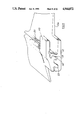
- FIG. 19 is a section through another can closure.
- FIG. 20 is another section.
- the figures illustrate profiled bead and recess fasteners comprising mating, complementary parts 11,12 of which one part has a recess generally shown as 14, and the other part has a bead generally shown as 13 which engages in the recess 14 to maintain the fastener closed against tension forces so directed as to tend to separate the two parts 11,12, the recess 14 having in cross section, an entrance 10 for the bead which is smaller in cross section than the bead cross section whereby to retain the bead 13 in the recess 14, the cross section of said entrance being adjustable by local elastic deformation to permit the bead 13 to enter or leave the recess 14 laterally, such deformation comprising flexure of one side 14' of the recess 14 by the bead 13 whilst the bead 13 comes out of contact with the other side 14" of the recess 14.
- Such flexure is effected by finger pressure on the bead part 13 which causes the bead 11 to rock on the recess part 12 to press the bead 13 against the said one side 14' of the recess 14.
- the bead part 11 comprises a lever 17 which rocks on the recess part 12 or, in the embodiment illustrated in FIGS. 1 to 5, on the bead part 11 while attached to the recess part 12, and carries the bead 13, such rocking urging the bead 13 against the side 14' of the recess 14 and out of contact with the other side 14" of the recess 14 whereby to adjust the cross section of the entrance 10 so that the bead 13 can be withdrawn, continued rocking then withdrawing the bead 13 from the recess 14.
- the lever 17 has a lever arm 17' adapted to be pushed by finger pressure towards the recess part 12 to effect the rocking which opens the entrance 10 to the recess 14.
- the lever 17 may otherwise, or in addition, have a lever arm 17" (FIG. 9) adapted to be lifted by finger pressure away from the recess part 12 to effect the rocking which opens the entrance to the recess 14.
- finger pressure at 141 causes the bead part 11 to slide on the recess part 12, however, to press the bead 13 against the side 14' of the recess 14.
- the bead 13 and entrance 10 to the recess 14 are so shaped that pushing the bead 13 towards the recess 14 against the said entrance 10 opens the entrance to admit the bead 13--the bead 13 in effect cams the side 14' of the recess 14 aside.
- the fasteners illustrated in FIGS. 1 to 5 and 9 are elongate, flexible fasteners with continuous, uniform cross sections, opening of which, after start thereon by said recess deformation, is continued progressively by pulling the two parts 11,12 apart, the bead 13 at the position where the fastener is half open holding open the entrance 10 to the recess 14 whereby the next adjacent bead portion can be pulled out.
- the fastener as shown in FIGS. 7 and 10, is an elongate flexible fastener which is segmented lengthwise, which is to say has a plurality of regularly-distributed breaks in its cross sections, so that the opening of any segment does not open the entrance of an adjacent segment sufficiently to allow the bead 13 therein to come out.
- the fastener is segmented lengthwise by notches 121. However, it may also be segmented by inclusions of reduced-modulus material at the locations of the notches 121.
- This fastener illustrated in FIG. 11 has a lengthwise section 111 at any part of which a local elastic deformation to permit the bead 13 to leave the recess 14 laterally cannot be effected except by, at an adjacent part, the bead 13 holding open the entrance to the recess 14 so that opening of the fastener cannot be started within said section.
- This fastener can be opened only from the lever segment 112, which is constructed as described in connection with FIG. 9.
- the illustrated fasteners may be made by extrusion, especially by extruding a plastics material such for example as polypropylene, nylon or polyester, which may then be drawn after extrusion to extend its length, reduce its cross section and increase its strength against plastic deformation under tension.
- the fastener may be co-extruded from different materials as, for example, from regular and low friction and/or low modulus/high modulus materials so as to arrange for desired frictional/flexural properties at different parts of the cross section.
- the shaded parts of the recess part 12 of FIG. 9, corresponding to the dashed lines thereon can be made of a low friction plastic co-extruded with another material for the rest of the cross section.
- the side 14' of the recess that is elastically deformed to open the recess to admit or release the bead 13 should be relatively rigid, so as not to deform itself under tension forces tending to separate the two parts of the fastener, yet have a flexible root, so that it can be bent aside, to open the recess, under local deformation.
- segmentation Whilst the segmentation of the elongate fastener has been described in regard to limiting the ability to pull the same open after a start, segmentation may also be used to control flexibility so, for example, as to provide that a fastener can be bent in one way or another, or twisted, or that a fastener can resist bending in one fashion or another, or can resist twisting, while at the same time retaining such flexibility where necessary and rigidity where necessary to open or close by intentional local deformation or by pulling apart after a start thereon, and not unintentionally.
- the fastener can be used as a closure for textiles, having attachment edges 11a,12a on parts 11 and 12 respectively, for connecting to textiles.
- the fastener can be sewn to textiles, the attachment edges 11a,12a being adapted for needle penetration, and being of reasonable strength, possibly being reinforced with textile thread or ribbon.
- the edges 11a,12a may have a sewing guide by which machine sewing is facilitated.
- Such sewing guide may be no more than a sighting line but may constitute a ridge such as the ridge 12b, FIGS. 9 and 10 which can be run against the presser foot of a sewing machine.
- the attachment edges 11a,12a which may be adhesive, can also be profiled to accept and grip a textile selvedges, as illustrated in FIG. 15, for attachment to a textile otherwise than by sewing, or to be reinforced by sewing.
- the edge 11a shown in FIG. 15, has a slit 11c with sharks' teeth ribs 11d into which the textile selvedge S is inserted.
- the inner faces of the slit 11c may be coated with a contact or other suitable adhesive.
- Any of the elongate fasteners described may have at least one closed end.
- Such end may be closed by welding or otherwise joining the two parts 11,12 together, or by fixing them in a common terminal such as end stop terminal 301 of FIG. 8 which has an enclosure 302 with a spring member 303 urging the two parts 11,12 together.
- Fasteners generally as described above may have two or more recesses and/or two or more beads, which beads or any one of which beads can be engaged in the recess or any one of the recesses, whereby to produce an adjustable width fastening.
- a fastener of FIG. 16 is shown as diagrammatically having two recesses 14(1),14(2) and two beads 13(1),13(2) and which therefore has four fastening positions, bead 13(1) going into either recess 14(1) or recess 14(2), and then bead 13(2) going into recess 14(1) or 14(2) whereby to position bead 13(1) at one or other of the four positions (a), (b), (c) or (d) indicated.
- the fastener shown in FIG. 9, like that shown in FIGS. 1 to 5, comprises an auxiliary bead 23 and recess 24 means assisting in maintaining the fastener closed under tension forces but separable together with the first mentioned bead 13 coming out of its recess 14.
- the FIG. 9 auxiliary bead and recess means 23,24 are readily engageable and form a pilot engagement which facilitates engagement of the primary bead 13 with its recess 14.
- the fastener may be fashioned as a sliderless elongate fastener, it may also be realised, as shown in FIGS. 12 and 13, as a slider fastener having slider means 121 having a cam face 121' running along the fastener effecting said local elastic deformation. Said slider means 121 effectively isolates the length of closed fastener on one side from the effect of the open fastener on the other side so as to maintain the fastener closed on the said one side.
- the slider for which positively engages over both sets of teeth the slider 121 need engage over only one part--as illustrated, the recess part 12--of the fastener, merely acting as a cam to locally operate the bead part 11 to locally deform the recess part to open the recess entrance 10 and urge the bead 13 out of the recess 14.
- the fastener may be, in another aspect, elongate but rigid against twisting about its length.
- a fastener can be incorporated on the edges of, or even integral with--structural panels 171, beams and the like or, in circular form, as a can closure 181 as shown in FIGS. 17 and 18. Opening and closing of the fastener can be progressive, as for the flexible fasteners aforementioned, or the entire length of the recess 14 may be opened at once so that the entire length of the bead 13 comes out of it at once.
- the fastener--in whatever form-- may incorporate means such as ridge 12b, FIGS. 9 and 10, protecting the parts against unintentional deformation.
- Ridge 12b of course, doubles as a presser foot guide as aforesaid.
- the fastener therein illustrated has mating, elongate parts 11 and 12 each including an additional bead 23 and groove or recess 24 which are also adapted to engage each other when fingertip pressure is applied, as illustrated in FIGS. 2 and 3, so that parts 11 and 12 are held in fastening engagement thereby as well as by the bead 13 and groove 14 as illustrated in FIG. 1.
- a latch 17 and cam 18 arrangement is provided for disengagement of the two halves.
- latch 17 is depressed by applying fingertip pressure and pivots around cam 18 until beads 13 and 23 are separated from grooves 14 and 24 and the fastener opened, as illustrated in FIGS. 4 and 5.
- the parts 11 and 12 are made of flexible material such as extruded polyamide, polyester or other polymer which allows for pivoting and twisting of beads 13 and 23, grooves 14 and 24, latch 17 and cam 18 when engaging and disengaging the two mating parts, as illustrated in FIGS. 2, 3, 4 and 5.
- the parts 11 and 12 can only be fastened by joining the parts at either end and by applying fingertip pressure in continuous motion from end to end.
- unfastening the two mating parts 11 and 12 can only be started by depressing the latch 17 at either end, whichever is the most convenient, and by applying fingertip pressure to latch 17 in a continuous motion the full length of the fastener.
- the two parts are held together by interlocking beads 13 and 23 and grooves 14 and 24 and which form hook type arrangements 22 and 22' and when engaged can form a snap fit, as illustrated in FIG. 1.
- parts 11 and 12 may be of flexible material, the degree of flexibility of the material will be dependent upon the usage for which the fastener is required.
- Extruded arrangements may have parts of the cross section of rigid, other parts of flexible extrudate, so that a fastener part may be made integral with, say, a building panel.
- Extruded arrangements may be of any extrudable material, for example, aluminium, which is compatible with the flexibility requirements.
- Non-extrudable materials can alternatively be moulded or shaped as by routing or in any other convenient way.
- a can closure disc 182, FIG. 18, is provided on its rim 181 with one part of the fastener, the can being provided with the other part.
- This arrangement will clearly be more useful with plastics material can closures which have inherent flexibility, so that they can be bent locally out of engagement with the rim of the can.
- a drum or canister or even a necked bottle closure 191 is shown in diagrammatic section in FIG. 19 in which there is a recess 14 on the rim or neck of the container 192 and a bead 13 on the closure 191.
- the recess 14 has an entrance 10 for the bead which is smaller than the bead cross section whereby to retain the bead in the recess against pulling the closure 191 away from the container 192.
- the recess 14 is bounded at inner radius, however, by a wall 193 which is flexible and which is segmented if necessary to accommodate any change in peripheral dimension occasioned by radial flexing.
- the bead 13 is on a web 195 which in cross section is seen as a lever 17 fulcrummed on the outer edge 196 of the rim or neck.
- the closure 191 has an inner seal or guide 197 which fits into the rim or neck and the whole closure 191 is flexible such that, closed, downward pressure on the centre 191' of the closure 195 pivots the lever 17 to cause the bead 13 to push the wall 193 towards the centre, the seal or guide descending somewhat into the container.
- the bead 13 in this movement comes away from the radially outer, inwardly facing wall 14" of the recess 14.
- FIG. 20 shows another arrangement in section.
- This can be regarded as an alternative form of cannister closure to that shown in FIG. 19, in which the lever 17 is arranged in the opposite sense so that the wall 193 is now at outer radius.
- this FIG. 20 may be viewed as a section of an elongate strip fastener which may be straight or curved.
- a removable fillet or locking strip 201 may be inserted in the space beyond the movable wall 193 to stop it moving. In a cannister closure this would act as a guard against accidental opening in transit and storage.
- the fillet or locking strip 201 could be a tear-off and throw-away member or it could be retainable for relocking the arrangement.
- a similar device could be used in connection with the embodiment of FIG. 9 where the locking strip would fit between the ridge 12b and the movable wall 14' of the recess 14 to prevent the recess 14 opening.
- the fastener being continuous in nature rather than comprised of individual interlocking parts of segments spaced apart (however closely) along the fastener, is ideal. Additional, e.g. labyrinth, seals can be built into the cross section if desired.
- FIGS. 6 and 8 illustrate a second series of profiled fastener designs according to the invention having first and second mating parts 11,12 of which the first part 11 has a bead and the second part 12 has a deformable recess 14, deformation of which permits lateral insertion of and removal of the bead 13.
- the first part 11 comprises a lever which rocks with regard to the second part 12, rocking of which causes the bead 13 to deform the recess 14 to permit removal of the bead 13.
- the lever 11 rocks on a deformable part 114 of the recess.
- the recess 14 comprises a face 14" mating with a face 11e of the bead 13 opposite a wall of the recess 14--the deformable part 14" constituting the wall--which bends away from said recess face 114 to permit the said bead face 11e to slide thereover and out of the recess 14.
- the two parts 11,12 have complementary surfaces 15,16 and are mutually deformable to bring said complementary surfaces 15,16 into and out of mutual contact, the one (in this case the surface 15 on part 11) moving by a combination of rolling and sliding on the other (surface 16 on part 12) to effect insertion of and removal of the bead 13 with regard to the recess 14.
- Each part 11,12 has an attachment selvedge 11a,12a for attaching to components, e.g. edges of a garment such as edges of a jacket or fly, to be fastened together by the fastener.
- the arrangement is such that with the fastener closed by the first and second parts 11,12 being interengaged with the bead 13 latched in the recess 14, tension between the said attachment selvedges 11a,12a confirms the inter-engagement.
- the bead 13 can only come out of the recess 14 if the recess 14 is opened, which is to say, if the wall 114 is deflected to the left as viewed in the drawings.
- the bead 13 comprises an essentially wedge shaped wall from the said first part 11 joining said first part 11 at its narrow end.
- Said second part 12 includes the wall 114 terminating in a lip 14c and capable of flexure at its root 14d, which forms one side of the recess 14.
- the root 14d is made of relatively shallow cross section to be more flexible than the rest of the part. It must be borne in mind, however, that the fastener as a whole will generally speaking need to be flexible so as to bend and twist in use, this without popping open under normal bending and twisting forces.
- FIG. 7 illustrates a fastener of which the wall 114 is segmented. This has the effect that when the fastened fastener is bent or twisted--as it will be in use especially in garments due to normal and abnormal body movements--the adjacent segments do not have any effect on each other and so do not tend to undo the fastener. Moreover, the fastener can be fastened (or unfastened) part way along without any tendency to propagate the closure or unfastening further along.
- the fastener illustrated in FIGS. 6 to 8 is easily openable and closable without the aid of a slider (although a slider could be used if desired) when made of material sufficiently flexible to enable it to be used as a garment closure, yet is adequately resistant to opening under forces ordinarily experienced in normal use. Opening and closing is effected by finger pressure rocking the one part on the other to open the latch, permitting withdrawing the bead. The opening and closing movement will be progressive along the fastener, as with regular metal zip fasteners, and facilitated by some twisting of one or both parts.
- the bead 13 could be arranged on the part 12, the recess on the part 11 if desired.
- mating faces can be coated to improve sealant qualities of the fastener.
Abstract
Profiled bead and recess fasteners have mating, complementary parts. One part has a bead which engages in a recess in the other. When engaged, there is resistance to separation under tension forces. The recess has an entrance for the bead which is smaller in section than the bead but which is adjustable by local deformation to pass the bead by flexure of one side of the recess by the bead which comes out of contact with the other side. The local deformation can be produced by finger pressure and so the fastener can be operated without the usual slider, although a slider can be provided for some purposes.
Description
This invention relates to profiled, bead and recess fasteners, such as may be made by extrusion of plastics material to substitute for the slide type fastener with interlocking teeth attached to stringers that can be sewn to edges e.g. of garments required to be releasably joined. Such profiled fasteners are to be found on plastic document wallets.
It is a problem with such fasteners that, largely on account of the flexible nature of the material of which they are made, they are relatively easy to spring open. To provide greater resistance against such springing open, while leaving the fastener easy to open intentionally, more complicated cross sectional latching arrangements have been proposed. These, however, require correspondingly complicated sliders. While such complicated sliders are realisable theoretically, in practise it is difficult, if not impossible, to produce them easily and inexpensively to the right tolerances, especially in the smaller sizes of fastener.
The present invention provides an improved fastener which can be made adequately secure against unintended springing open and one which can be opened and closed without the need for a slider, although a slider might be provided while retaining the other improvements.
The invention comprises a profiled bead and recess fastener comprising mating, complementary parts of which one part has a recess and the other part has a bead which engages in the recess to maintain the fastener closed against tension forces so directed as to tend to separate the two parts, the recess having, in cross section, an entrance for the bead, which is smaller in cross section than the bead cross section whereby to retain the bead in the recess, the cross section of said entrance being adjustable by local elastic deformation to permit the bead to enter or leave the recess laterally, such deformation comprising flexure of one side of the recess by the bead whilst the bead comes out of contact with the other side of the recess.
Such flexure may be effected by finger pressure on the bead part. Said finger pressure may cause the bead part to rock on the recess part to press the bead against the said one side of the recess.
Said bead part may comprise a lever which rocks on the recess part and carries the bead, such rocking urging the bead against said one side of the recess and out of contact with the other side of the recess whereby to adjust the cross section of the entrance so that the bead can be withdrawn, continued rocking then withdrawing the bead from the recess. Said lever may have a lever arm adapted to be pushed by finger pressure towards the recess part to effect the rocking which opens the entrance to the recess. Said lever may otherwise, or in addition, have a lever arm adapted to be lifted by finger pressure away from the recess part to effect the rocking which opens the entrance to the recess.
Said finger pressure may cause the bead part to slide on the recess part, however, to press the bead against the said one side of the recess.
The bead and entrance to the recess may be so shaped that pushing the bead towards the recess against the said entrance opens the entrance to admit the bead.
At least parts which move over each other in the actions of opening and closing may have low friction.
The fastener may be an elongate, flexible fastener with a continuous, uniform cross section, opening of which, after a start thereon by said recess deformation, is continued progresssively by pulling the two parts apart, the bead at the position where the fastener is half open holding open the entrance to the recess whereby the next adjacent bead portion can be pulled out.
There may be at least one break, however, in the continuity of the cross section along the fastener whereby the said progressive opening is arrested.
The fastener may, however, be an elongate flexible fastener which is segmented lengthwise so that the opening of any segment does not open the entrance of an adjacent segment sufficiently to allow the bead therein to come out. The fastener may be segmented lengthwise by notches or by inclusions of reduced-modulus material.
A fastener may have at least one lengthwise section at any part of which local elastic deformation to permit the bead to leave the recess laterally cannot be effected except by, at an adjacent part, the bead holding open the entrance to the recess, so that opening of the fastener cannot be started within said section.
The fastener may be made by extrusion, especially by extruding a plastics material which may then be drawn after extrusion. The fastener may be co-extruded from different materials as, for example, from regular and low friction and/or low modulus/high modulus materials so as to arrange for desired frictional/flexural properties at different parts of the cross section.
The fastener may be intended for use as a closure for textiles, having attachment edges, one on each of said parts, for connecting to textiles. The fastener may be adapted for sewing to textiles by the attachment edges being adapted for needle penetration, and being of reasonable strength, possibly being reinforced with textile thread or ribbon, and may have a sewing guide by which machine sewing is facilitated.
The attachment edges may also be profiled to accept and grip a textile selvedge, and they may be adhesive.
An elongate fastener may have at least one closed end.
A fastener may have two or more recesses and/or two or more beads, which bead or any one of which beads can be engaged in the recess or any one of the recesses, whereby to produce an adjustable width fastening.
The fastener may comprise auxiliary bead and recess means assisting in maintaining the fastener closed under tension forces but separable together with the first mentioned bead coming out of its recess. Said auxiliary bead and recess means may be readily engageable and form pilot engagement means facilitating engaging the first mentioned bead with its recess.
Although the fastener may be fashioned as a sliderless elongate fastener, it may also be realised as a slider fastener having slider means running along the fastener effecting said local elastic deformation. Said slider means may isolate the length of closed fastener on one side from the effect of the open fastener on the other side so as to maintain the slider closed on the said one side.
The fastener may be, in another aspect, elongate but rigid against twisting about its length. Such a fastener may be incorporated on the edges of, or even integral with, structural panels, beams and the like or, in circular form, as a can closure. Opening and closing of the fastener may be progressive, as for the flexible fasteners aforementioned, or the entire length of the recess may be opened at once so that the entire length of the bead comes out of it at once.
The fastener--in whatever form--may incorporate guard means protecting the parts against unintentional separation.
Embodiments of fasteners according to the invention will now be described with respect to the accompanying drawings, in which:
FIGS. 1 to 10 are of one embodiment:
FIG. 1 is a perspective view showing particularly the cross section;
FIGS. 2 and 3 illustrate, in cross sectional form, the action of the engagement of the two mating parts;
FIGS. 4 and 5 illustrate, in cross sectional form, the action of disengagement of the two mating parts;
FIGS. 6 to 8 are of another embodiment:
FIG. 6 is a perspective view showing essentially, however, the cross section of the two parts of a fastener;
FIG. 7 a perspective view showing the two parts of a fastener like that of FIG. 6, but segmented;
FIG. 8 is a cross sectional view of an end stop for an arrangement such as is illustrated in FIGS. 6 and 7;
and FIGS. 9 to 18 illustrate features of further variants:
FIG. 9 is a perspective view of a further embodiment, showing particularly the cross section;
FIG. 10 is a view like FIG. 9 of a varient of the embodiment thereof;
FIG. 11 is a view like FIG. 9 of a further embodiment thereof;
FIG. 12 is a cross section of a slider arrangement for a variant of the embodiment of FIG. 9;
FIG. 13 is a view in the direction of arrow A of FIG. 12;
FIG. 14 is a cross section of a yet further embodiment;
FIG. 15 is a cross section of an attachment edge;
FIG. 16 is a cross section of another variant;
FIG. 17 is a cross section showing a fastener integral with rigid panels;
FIG. 18 is a cross sectional elevation of a can closure;
FIG. 19 is a section through another can closure; and
FIG. 20 is another section.
The figures illustrate profiled bead and recess fasteners comprising mating, complementary parts 11,12 of which one part has a recess generally shown as 14, and the other part has a bead generally shown as 13 which engages in the recess 14 to maintain the fastener closed against tension forces so directed as to tend to separate the two parts 11,12, the recess 14 having in cross section, an entrance 10 for the bead which is smaller in cross section than the bead cross section whereby to retain the bead 13 in the recess 14, the cross section of said entrance being adjustable by local elastic deformation to permit the bead 13 to enter or leave the recess 14 laterally, such deformation comprising flexure of one side 14' of the recess 14 by the bead 13 whilst the bead 13 comes out of contact with the other side 14" of the recess 14.
Such flexure is effected by finger pressure on the bead part 13 which causes the bead 11 to rock on the recess part 12 to press the bead 13 against the said one side 14' of the recess 14.
The bead part 11 comprises a lever 17 which rocks on the recess part 12 or, in the embodiment illustrated in FIGS. 1 to 5, on the bead part 11 while attached to the recess part 12, and carries the bead 13, such rocking urging the bead 13 against the side 14' of the recess 14 and out of contact with the other side 14" of the recess 14 whereby to adjust the cross section of the entrance 10 so that the bead 13 can be withdrawn, continued rocking then withdrawing the bead 13 from the recess 14. The lever 17 has a lever arm 17' adapted to be pushed by finger pressure towards the recess part 12 to effect the rocking which opens the entrance 10 to the recess 14. The lever 17 may otherwise, or in addition, have a lever arm 17" (FIG. 9) adapted to be lifted by finger pressure away from the recess part 12 to effect the rocking which opens the entrance to the recess 14.
In the embodiment illustrated in FIG. 14, finger pressure at 141 causes the bead part 11 to slide on the recess part 12, however, to press the bead 13 against the side 14' of the recess 14.
In all embodiments, the bead 13 and entrance 10 to the recess 14, are so shaped that pushing the bead 13 towards the recess 14 against the said entrance 10 opens the entrance to admit the bead 13--the bead 13 in effect cams the side 14' of the recess 14 aside.
At least those parts of the fastener which move over each other in the actions of opening and closing namely the surfaces of the bead 13 and recess 14 indicated by broken lines `F`--see FIG. 9--have low friction.
The fasteners illustrated in FIGS. 1 to 5 and 9 are elongate, flexible fasteners with continuous, uniform cross sections, opening of which, after start thereon by said recess deformation, is continued progressively by pulling the two parts 11,12 apart, the bead 13 at the position where the fastener is half open holding open the entrance 10 to the recess 14 whereby the next adjacent bead portion can be pulled out.
There may be at least one break, however, in the continuity of the cross section along the fastener whereby the said progressive opening is arrested.
The fastener, as shown in FIGS. 7 and 10, is an elongate flexible fastener which is segmented lengthwise, which is to say has a plurality of regularly-distributed breaks in its cross sections, so that the opening of any segment does not open the entrance of an adjacent segment sufficiently to allow the bead 13 therein to come out. The fastener is segmented lengthwise by notches 121. However, it may also be segmented by inclusions of reduced-modulus material at the locations of the notches 121.
This fastener illustrated in FIG. 11 has a lengthwise section 111 at any part of which a local elastic deformation to permit the bead 13 to leave the recess 14 laterally cannot be effected except by, at an adjacent part, the bead 13 holding open the entrance to the recess 14 so that opening of the fastener cannot be started within said section. This fastener can be opened only from the lever segment 112, which is constructed as described in connection with FIG. 9.
The illustrated fasteners may be made by extrusion, especially by extruding a plastics material such for example as polypropylene, nylon or polyester, which may then be drawn after extrusion to extend its length, reduce its cross section and increase its strength against plastic deformation under tension. The fastener may be co-extruded from different materials as, for example, from regular and low friction and/or low modulus/high modulus materials so as to arrange for desired frictional/flexural properties at different parts of the cross section. Thus for example the shaded parts of the recess part 12 of FIG. 9, corresponding to the dashed lines thereon, can be made of a low friction plastic co-extruded with another material for the rest of the cross section.
This can be of particular importance also in connection with achieving the right balance of flexural properties.
Thus the side 14' of the recess that is elastically deformed to open the recess to admit or release the bead 13 should be relatively rigid, so as not to deform itself under tension forces tending to separate the two parts of the fastener, yet have a flexible root, so that it can be bent aside, to open the recess, under local deformation.
Whilst the segmentation of the elongate fastener has been described in regard to limiting the ability to pull the same open after a start, segmentation may also be used to control flexibility so, for example, as to provide that a fastener can be bent in one way or another, or twisted, or that a fastener can resist bending in one fashion or another, or can resist twisting, while at the same time retaining such flexibility where necessary and rigidity where necessary to open or close by intentional local deformation or by pulling apart after a start thereon, and not unintentionally.
The fastener can be used as a closure for textiles, having attachment edges 11a,12a on parts 11 and 12 respectively, for connecting to textiles. The fastener can be sewn to textiles, the attachment edges 11a,12a being adapted for needle penetration, and being of reasonable strength, possibly being reinforced with textile thread or ribbon. The edges 11a,12a may have a sewing guide by which machine sewing is facilitated.
Such sewing guide may be no more than a sighting line but may constitute a ridge such as the ridge 12b, FIGS. 9 and 10 which can be run against the presser foot of a sewing machine.
The attachment edges 11a,12a, which may be adhesive, can also be profiled to accept and grip a textile selvedges, as illustrated in FIG. 15, for attachment to a textile otherwise than by sewing, or to be reinforced by sewing.
The edge 11a shown in FIG. 15, has a slit 11c with sharks' teeth ribs 11d into which the textile selvedge S is inserted. The inner faces of the slit 11c may be coated with a contact or other suitable adhesive.
Any of the elongate fasteners described may have at least one closed end.
Such end may be closed by welding or otherwise joining the two parts 11,12 together, or by fixing them in a common terminal such as end stop terminal 301 of FIG. 8 which has an enclosure 302 with a spring member 303 urging the two parts 11,12 together.
Fasteners generally as described above may have two or more recesses and/or two or more beads, which beads or any one of which beads can be engaged in the recess or any one of the recesses, whereby to produce an adjustable width fastening. A fastener of FIG. 16 is shown as diagrammatically having two recesses 14(1),14(2) and two beads 13(1),13(2) and which therefore has four fastening positions, bead 13(1) going into either recess 14(1) or recess 14(2), and then bead 13(2) going into recess 14(1) or 14(2) whereby to position bead 13(1) at one or other of the four positions (a), (b), (c) or (d) indicated.
The fastener shown in FIG. 9, like that shown in FIGS. 1 to 5, comprises an auxiliary bead 23 and recess 24 means assisting in maintaining the fastener closed under tension forces but separable together with the first mentioned bead 13 coming out of its recess 14. The FIG. 9 auxiliary bead and recess means 23,24, however, are readily engageable and form a pilot engagement which facilitates engagement of the primary bead 13 with its recess 14.
Although the fastener may be fashioned as a sliderless elongate fastener, it may also be realised, as shown in FIGS. 12 and 13, as a slider fastener having slider means 121 having a cam face 121' running along the fastener effecting said local elastic deformation. Said slider means 121 effectively isolates the length of closed fastener on one side from the effect of the open fastener on the other side so as to maintain the fastener closed on the said one side.
Unlike conventional fasteners with interlocking teeth, the slider for which positively engages over both sets of teeth, the slider 121 need engage over only one part--as illustrated, the recess part 12--of the fastener, merely acting as a cam to locally operate the bead part 11 to locally deform the recess part to open the recess entrance 10 and urge the bead 13 out of the recess 14.
The fastener may be, in another aspect, elongate but rigid against twisting about its length. Such a fastener can be incorporated on the edges of, or even integral with--structural panels 171, beams and the like or, in circular form, as a can closure 181 as shown in FIGS. 17 and 18. Opening and closing of the fastener can be progressive, as for the flexible fasteners aforementioned, or the entire length of the recess 14 may be opened at once so that the entire length of the bead 13 comes out of it at once.
The fastener--in whatever form--may incorporate means such as ridge 12b, FIGS. 9 and 10, protecting the parts against unintentional deformation. Ridge 12b, of course, doubles as a presser foot guide as aforesaid.
Reverting now to FIGS. 1 to 5, the fastener therein illustrated has mating, elongate parts 11 and 12 each including an additional bead 23 and groove or recess 24 which are also adapted to engage each other when fingertip pressure is applied, as illustrated in FIGS. 2 and 3, so that parts 11 and 12 are held in fastening engagement thereby as well as by the bead 13 and groove 14 as illustrated in FIG. 1.
A latch 17 and cam 18 arrangement is provided for disengagement of the two halves. To disengage, latch 17 is depressed by applying fingertip pressure and pivots around cam 18 until beads 13 and 23 are separated from grooves 14 and 24 and the fastener opened, as illustrated in FIGS. 4 and 5.
The parts 11 and 12 are made of flexible material such as extruded polyamide, polyester or other polymer which allows for pivoting and twisting of beads 13 and 23, grooves 14 and 24, latch 17 and cam 18 when engaging and disengaging the two mating parts, as illustrated in FIGS. 2, 3, 4 and 5.
In use in, say, a fastener for clothing, replacing the conventional slide type fastener, the parts 11 and 12 can only be fastened by joining the parts at either end and by applying fingertip pressure in continuous motion from end to end. Alternatively, unfastening the two mating parts 11 and 12 can only be started by depressing the latch 17 at either end, whichever is the most convenient, and by applying fingertip pressure to latch 17 in a continuous motion the full length of the fastener.
The two parts are held together by interlocking beads 13 and 23 and grooves 14 and 24 and which form hook type arrangements 22 and 22' and when engaged can form a snap fit, as illustrated in FIG. 1.
Closing of the fastener beings at one end, or the other, with beads 13 and 23 being inserted into grooves 14 and 24, when fingertip pressure is applied and the fingertip is run from one end to the other, with continuous pressure being applied, and the two mating parts 11 and 12 snap into engagement, as illustrated in FIGS. 2 and 3.
Opening of the fastener beings at one end, or the other, with fingertip pressure being applied to latch 17 and latch 17 pivots around cam 18, thus allowing beads 13 and 23 to separate from grooves 14 and 24, as illustrated in FIGS. 4 and 5.
Whilst, as noted above, parts 11 and 12 may be of flexible material, the degree of flexibility of the material will be dependent upon the usage for which the fastener is required. Extruded arrangements may have parts of the cross section of rigid, other parts of flexible extrudate, so that a fastener part may be made integral with, say, a building panel. Extruded arrangements may be of any extrudable material, for example, aluminium, which is compatible with the flexibility requirements. Non-extrudable materials can alternatively be moulded or shaped as by routing or in any other convenient way.
With a flexible arrangement, it may be noted that it is also possible to provide non-rectilinear extrusions or mouldings so that the fasteners can follow a circular, elliptical or other curved path such as might be useful e.g. for the closures of FIGS. 18 and 19. A can closure disc 182, FIG. 18, is provided on its rim 181 with one part of the fastener, the can being provided with the other part. This arrangement will clearly be more useful with plastics material can closures which have inherent flexibility, so that they can be bent locally out of engagement with the rim of the can.
A drum or canister or even a necked bottle closure 191 is shown in diagrammatic section in FIG. 19 in which there is a recess 14 on the rim or neck of the container 192 and a bead 13 on the closure 191. The recess 14 has an entrance 10 for the bead which is smaller than the bead cross section whereby to retain the bead in the recess against pulling the closure 191 away from the container 192. The recess 14 is bounded at inner radius, however, by a wall 193 which is flexible and which is segmented if necessary to accommodate any change in peripheral dimension occasioned by radial flexing. The bead 13 is on a web 195 which in cross section is seen as a lever 17 fulcrummed on the outer edge 196 of the rim or neck. The closure 191 has an inner seal or guide 197 which fits into the rim or neck and the whole closure 191 is flexible such that, closed, downward pressure on the centre 191' of the closure 195 pivots the lever 17 to cause the bead 13 to push the wall 193 towards the centre, the seal or guide descending somewhat into the container. The bead 13 in this movement comes away from the radially outer, inwardly facing wall 14" of the recess 14. The wall 193, once the bead 13 is clear of it, snaps back to hold the bead 13 clear of the recess. Release of pressure at the middle 195 of the closure 191 allows the springiness of the lever 17 to lift the closure, and it can now be taken off. Replacement is simply a matter of pushing it downwardly so that the bead 13 pushes the wall 193 inwardly to open the mouth 10 of the recess 14 to admit the bead 13, whereupon the wall 193 snaps back into place to lock the closure on to the rim.
FIG. 20 shows another arrangement in section. This can be regarded as an alternative form of cannister closure to that shown in FIG. 19, in which the lever 17 is arranged in the opposite sense so that the wall 193 is now at outer radius. Alternatively, this FIG. 20 may be viewed as a section of an elongate strip fastener which may be straight or curved. In any event, a removable fillet or locking strip 201 may be inserted in the space beyond the movable wall 193 to stop it moving. In a cannister closure this would act as a guard against accidental opening in transit and storage. The fillet or locking strip 201 could be a tear-off and throw-away member or it could be retainable for relocking the arrangement. A similar device could be used in connection with the embodiment of FIG. 9 where the locking strip would fit between the ridge 12b and the movable wall 14' of the recess 14 to prevent the recess 14 opening.
For conventional situations where airtightness and watertightness are required, the fastener, being continuous in nature rather than comprised of individual interlocking parts of segments spaced apart (however closely) along the fastener, is ideal. Additional, e.g. labyrinth, seals can be built into the cross section if desired.
FIGS. 6 and 8 illustrate a second series of profiled fastener designs according to the invention having first and second mating parts 11,12 of which the first part 11 has a bead and the second part 12 has a deformable recess 14, deformation of which permits lateral insertion of and removal of the bead 13.
The first part 11 comprises a lever which rocks with regard to the second part 12, rocking of which causes the bead 13 to deform the recess 14 to permit removal of the bead 13.
The lever 11 rocks on a deformable part 114 of the recess.
The recess 14 comprises a face 14" mating with a face 11e of the bead 13 opposite a wall of the recess 14--the deformable part 14" constituting the wall--which bends away from said recess face 114 to permit the said bead face 11e to slide thereover and out of the recess 14.
The two parts 11,12 have complementary surfaces 15,16 and are mutually deformable to bring said complementary surfaces 15,16 into and out of mutual contact, the one (in this case the surface 15 on part 11) moving by a combination of rolling and sliding on the other (surface 16 on part 12) to effect insertion of and removal of the bead 13 with regard to the recess 14.
Each part 11,12 has an attachment selvedge 11a,12a for attaching to components, e.g. edges of a garment such as edges of a jacket or fly, to be fastened together by the fastener. The arrangement is such that with the fastener closed by the first and second parts 11,12 being interengaged with the bead 13 latched in the recess 14, tension between the said attachment selvedges 11a,12a confirms the inter-engagement. The bead 13 can only come out of the recess 14 if the recess 14 is opened, which is to say, if the wall 114 is deflected to the left as viewed in the drawings. Tension between the attachment selvedges 11a,12a, however, tends to draw the selvedges into a common plane, if they are not in one already, which will tend not to deflect this wall 114 to the left but lock the two parts 11,12 even more firmly together.
The bead 13 comprises an essentially wedge shaped wall from the said first part 11 joining said first part 11 at its narrow end. Said second part 12 includes the wall 114 terminating in a lip 14c and capable of flexure at its root 14d, which forms one side of the recess 14. The root 14d is made of relatively shallow cross section to be more flexible than the rest of the part. It must be borne in mind, however, that the fastener as a whole will generally speaking need to be flexible so as to bend and twist in use, this without popping open under normal bending and twisting forces.
FIG. 7 illustrates a fastener of which the wall 114 is segmented. This has the effect that when the fastened fastener is bent or twisted--as it will be in use especially in garments due to normal and abnormal body movements--the adjacent segments do not have any effect on each other and so do not tend to undo the fastener. Moreover, the fastener can be fastened (or unfastened) part way along without any tendency to propagate the closure or unfastening further along.
The fastener illustrated in FIGS. 6 to 8 is easily openable and closable without the aid of a slider (although a slider could be used if desired) when made of material sufficiently flexible to enable it to be used as a garment closure, yet is adequately resistant to opening under forces ordinarily experienced in normal use. Opening and closing is effected by finger pressure rocking the one part on the other to open the latch, permitting withdrawing the bead. The opening and closing movement will be progressive along the fastener, as with regular metal zip fasteners, and facilitated by some twisting of one or both parts.
It will be seen that such rocking by finger pressure can be effected from either side of the fastener, so that the fastener can be used with either the part 11 or part 12 as the accessible part, i.e. to the outside of a garment.
The bead 13 could be arranged on the part 12, the recess on the part 11 if desired.
In any event, mating faces can be coated to improve sealant qualities of the fastener.
It will be appreciated that it is not intended to limit the invention to the above example only, many variations, such as might readily occur to one skilled in the art, being possible, without departing from the scope thereof as defined by the appended claims.
Claims (23)
1. A profiled bead and recess fastener comprising mating, complementary parts of which one part has a recess and the other part has a bead which engages in the recess to maintain the fastener closed against tension forces so directed as to tend to separate the two parts, the recess having in cross section, an entrance for the bead, which is smaller in cross section than the bead cross section whereby to retain the bead in the recess, the cross section of said entrance being adjustable by local elastic deformation to permit the bead to enter or leave the recess laterally, such local deformation to permit the bead to leave the recess being caused by flexure of one side of the recess by the bead whilst the bead comes out of contact with the other side of the recess without applying tension forces between the two parts.
2. A fastener according to claim 1, in which such flexure is effected by finger pressure on the bead part.
3. A fastener according to claim 2, in which said finger pressure causes the bead part to rock on the recess part to press the bead against the said one side of the recess.
4. A fastener according to claim 2, in which said finger pressure causes the bead part to slide on the recess part to press the bead against the said one side of the recess.
5. A fastener according to claim 1, in which the bead and entrance to the recess are so shaped that pushing the bead towards the recess against the said entrance opens the entrance to admit the bead.
6. A fastener according to claim 1, in which at least parts which move over each other in the actions of opening and closing have low friction.
7. A fastener according to claim 1, which is an elongate, flexible fastener with a continuous, uniform cross section over a substantial portion of the length of the fastener, opening of which, after a start thereon by said recess deformation, is continued progressively over such length by pulling the two parts apart, the bead at the position where the fastener is half open holding open the entrance to the recess whereby the next adjacent bead portion can be pulled out.
8. A fastener according to claim 7, in which there is at least one break in the continuity of the cross section along the fastener whereby the said progressive opening is arrested.
9. A fastener according to claim 7, intended for use as closure for textiles, having attachment edges, one on each of said parts, for connecting to textiles.
10. A fastener according to claim 9, adapted for sewing to a textile, having a sewing guide.
11. A fastener according to claim 7, having two or more recesses and/or two or more beads, any one of which beads can be engaged in any one of which recesses, whereby to produce an adjustable width fastening.
12. A fastener according to claim 7, comprising auxiliary bead and recess means assisting in maintaining the fastener closed under tension forces but separable together with the first mentioned bead coming out of its recess.
13. A fastener according to claim 12, said auxiliary bead and recess means being readily engageable and forming pilot engagement means facilitating engaging the first mentioned bead with its recess.
14. A fastener according to claim 7, having slider means running along the fastener effecting said local elastic deformation.
15. A fastener according to claim 14, in which said slider means isolate the length of closed fastener on one side from the effect of the open fastener on the other side so as to maintain the slider closed on the said one side.
16. A fastener according to claim 1, which is an elongate flexible fastener which is segmented lengthwise so that the opening of any segment does not open the entrance of an adjacent segment sufficiently to allow the bead therein to come out.
17. A fastener according to claim 16, which is segmented lengthwise by notches.
18. A fastener according to claim 16, which is segmented lengthwise by inclusion of reduced modulus material.
19. A fastener according to claim 1, incorporating guard means protecting the parts against unintentional deformation.
20. A profiled bead and recess fastener comprising mating, complementary parts of which one part has a recess and the other part has a bead which engaged in the recess to maintain the fastener closed against tension forces so directed as to tend to separate the two parts, the recess having in cross section, an entrance for the bead, which is smaller in cross section than the bead cross section whereby to retain the bead in the recess, the cross section of said entrance being adjustable by local elastic deformation to permit the bead to enter of leave the recess laterally, such deformation comprising flexure of one side of the recess by the bead whilst the bead comes out of contact with the other side of the recess, said bead part comprising a lever which rocks on the recess part and carried the bead, such rocking urging the bead against said one side of the recess and out of contact with the other side of the recess whereby to adjust the cross section of the entrance so that the bead can be withdrawn, continued rocking then withdrawing the bead from the recess.
21. A fastener according to claim 20, in which said lever has a lever arm adapted to be pushed by finger pressure towards the recess part to effect the rocking which opens the entrance to the recess.
22. A fastener according to claim 20, in which said lever has a lever arm adapted to be lifted by finger pressure away from the recess part to effect the rocking which opens the entrance to the recess.
23. A profiled bead and recess fastener comprising mating, complementary parts of which one part has a recess and the other part has a bead which engages in the recess to maintain the fastener closed against tension forces so directed as to tend to separate the two parts, the recess having in cross section, an entrance for the bead, which is smaller in cross section than the bead cross section whereby to retain the bead in the recess, the cross section of said entrance being adjustable by local elastic deformation to permit the bead to enter or leave the recess laterally, such deformation comprising flexure of one side of the recess by the bead whilst the bead comes out of contact with the other side of the recess, said fastener being an elongate, flexible fastener with a continuous, uniform cross section, opening of which, after a start thereon by said recess deformation, is continued progressively by pulling the two parts apart, the bead at the position where the fastener is half open holding open the entrance to the recess whereby the next adjacent bead portion can be pulled out, said fastener having at least one lengthwise section at any part of which local elastic deformation to permit the bead to leave the recess laterally cannot be effected except by, at an adjacent part, the bead holding open the entrance to the recess, so that opening of the fastener cannot be started within said section.
Applications Claiming Priority (4)
| Application Number | Priority Date | Filing Date | Title |
|---|---|---|---|
| GB8815164 | 1988-06-25 | ||
| GB888815164A GB8815164D0 (en) | 1988-06-25 | 1988-06-25 | Profiled fasteners |
| GB8826131 | 1988-11-08 | ||
| GB888826131A GB8826131D0 (en) | 1988-11-08 | 1988-11-08 | Profiled fastener |
Publications (1)
| Publication Number | Publication Date |
|---|---|
| US4944072A true US4944072A (en) | 1990-07-31 |
Family
ID=26294080
Family Applications (1)
| Application Number | Title | Priority Date | Filing Date |
|---|---|---|---|
| US07/368,775 Expired - Lifetime US4944072A (en) | 1988-06-25 | 1989-06-20 | Profiled fasteners |
Country Status (7)
| Country | Link |
|---|---|
| US (1) | US4944072A (en) |
| EP (1) | EP0349175B1 (en) |
| JP (1) | JPH0276914A (en) |
| DE (1) | DE68913371T2 (en) |
| DK (1) | DK312789A (en) |
| GB (1) | GB2220443A (en) |
| PT (1) | PT90966B (en) |
Cited By (40)
| Publication number | Priority date | Publication date | Assignee | Title |
|---|---|---|---|---|
| US5097687A (en) * | 1990-10-24 | 1992-03-24 | Turrin David J | Releasable toe strap for a bicycle pedal |
| US5307552A (en) * | 1990-03-09 | 1994-05-03 | Dowbrands L.P. | Method of making a zipper for reclosable thermoplastic bag |
| US5425327A (en) * | 1992-07-15 | 1995-06-20 | Aldon Industries, Inc. | Boat canopy mounting system |
| US5442838A (en) * | 1994-06-17 | 1995-08-22 | Mobil Oil Corporation | Rolling action zipper profile and slider |
| US5664296A (en) * | 1996-06-26 | 1997-09-09 | Reynolds Consumer Products Inc. | Closure arrangement having a reclosable seal |
| US5699601A (en) * | 1995-08-30 | 1997-12-23 | Ford Motor Company | Snap tab fastener and disassembly tool therefor |
| US5851071A (en) * | 1997-09-11 | 1998-12-22 | Rayton Packaging, Inc. | Plastic bag with permanent sealing zipper |
| US5934806A (en) * | 1996-05-22 | 1999-08-10 | Tomic; Mladomir | Closure arrangement for reclosable bag and method thereof |
| US6026761A (en) * | 1997-01-31 | 2000-02-22 | Taylor Made Systems Bradenton, Inc. | Canopy mounting system |
| US6047450A (en) * | 1999-02-09 | 2000-04-11 | Illinois Tool Works Inc. | Slide zipper assembly |
| US6061882A (en) * | 1995-07-05 | 2000-05-16 | Padis Preisauszeichnung + Display Systeme GmbH & Co. Vertriebs-K.G. | Clamping device and associated holder |
| US6082897A (en) * | 1999-01-13 | 2000-07-04 | Fres-Co System Usa, Inc. | Segmented snap closure for flexible packages and flexible packages including the same |
| US6132089A (en) * | 1999-01-13 | 2000-10-17 | Fres-Co System Usa, Inc. | Adhesively secured snap closure for flexible packages and flexible packages including the same |
| US6170696B1 (en) | 1996-03-04 | 2001-01-09 | The Glad Products Company | Sealing container |
| US6256847B1 (en) * | 1996-06-28 | 2001-07-10 | 3M Innovative Properties Company | Strap fastener |
| US6293701B1 (en) | 1998-11-18 | 2001-09-25 | Mladomir Tomic | Resealable closure mechanism having slider device and methods |
| US6461042B1 (en) | 2000-05-01 | 2002-10-08 | Reynolds Consumer Products, Inc. | Resealable closure mechanism having a slider device |
| US6467647B1 (en) | 1997-03-18 | 2002-10-22 | The Glad Products Company | Seating container |
| US6487759B1 (en) * | 1999-11-16 | 2002-12-03 | Ykk Corporation | Engaging member and manufacturing method thereof |
| US6594873B2 (en) * | 2001-11-08 | 2003-07-22 | Claudio Argento | Slide closures for touch fasteners |
| US6594872B2 (en) | 2001-08-17 | 2003-07-22 | The Glad Products Company | Interlocking closure device |
| US20030194155A1 (en) * | 2002-04-11 | 2003-10-16 | Plourde Eric Paul | Slider-operated rocking zipper for reclosable packaging |
| US6679027B2 (en) | 2000-11-29 | 2004-01-20 | Reynolds Consumer Products, Inc. | Resealable closure mechanism having a slider device and methods |
| US6687962B2 (en) | 2002-01-16 | 2004-02-10 | Velcro Industries B.V. | Fastener element patterning |
| US6789393B2 (en) | 2002-02-11 | 2004-09-14 | S.C. Johnson Home Storage, Inc. | Container with pressure relief and lid and method of manufacture therefor |
| US20060008186A1 (en) * | 2004-07-12 | 2006-01-12 | Maximillian Kusz | Reclosable child resistant package |
| US7097063B2 (en) | 2002-01-29 | 2006-08-29 | The Glad Products Company | Plate container with detachable cover |
| US20060269171A1 (en) * | 2005-05-26 | 2006-11-30 | Turvey Robert R | Slider with laterally displaceable engagement members |
| US20060265844A1 (en) * | 2005-05-26 | 2006-11-30 | Ackerman Bryan L | Apparatus and method of operatively retaining an actuating member on an elongate closure mechanism |
| US20060265843A1 (en) * | 2005-05-26 | 2006-11-30 | Ackerman Bryan L | Slider for closure assembly |
| US20060282996A1 (en) * | 2004-04-09 | 2006-12-21 | Ackerman Bryan L | Closure assembly with slider |
| US20070289108A1 (en) * | 2006-05-31 | 2007-12-20 | Illinois Tool Works Inc. | Press-to-open zippers for reclosable packages |
| US20080073368A1 (en) * | 2006-08-23 | 2008-03-27 | Richard Custer | Containers with discontinuous seal |
| US20100187836A1 (en) * | 2007-06-16 | 2010-07-29 | David Mark Mason | Latch |
| US7797802B2 (en) | 2007-11-29 | 2010-09-21 | S.C. Johnson & Son, Inc. | Actuating member for a closure assembly and method |
| WO2011160173A1 (en) * | 2010-06-22 | 2011-12-29 | Joinlock Pty Ltd | Key and keyway connectors |
| WO2014153598A1 (en) * | 2013-03-27 | 2014-10-02 | Joinlock Pty Ltd | Key and keyway connectors |
| US20140341639A1 (en) * | 2012-01-18 | 2014-11-20 | Illinois Tool Works Inc. | Locking connector assembly |
| US20190277307A1 (en) * | 2018-03-08 | 2019-09-12 | Sunonwealth Electric Machine Industry Co., Ltd. | Fan |
| WO2020227371A1 (en) | 2019-05-07 | 2020-11-12 | Precision Dynamics Corporation | Clasp assembly |
Families Citing this family (4)
| Publication number | Priority date | Publication date | Assignee | Title |
|---|---|---|---|---|
| GB9010447D0 (en) * | 1990-05-10 | 1990-07-04 | Robson Peter M | Linear fasteners |
| FR2684277B1 (en) * | 1991-11-28 | 1994-07-22 | Mallet Michel | SLIDING SYSTEM FOR CLOSING CLOTHING, IMPLEMENTED BY THE CONTINUOUS PRESSURE OF TWO HAND FINGERS SLIDING ALONG THE SAID SYSTEM. |
| GB2445950A (en) * | 2007-01-27 | 2008-07-30 | Touac Internat Ltd | Elongate fastener having first and second extrusions and a lever |
| JP5953043B2 (en) * | 2012-01-04 | 2016-07-13 | シーアイ化成株式会社 | Gazette bag with fitting |
Citations (32)
| Publication number | Priority date | Publication date | Assignee | Title |
|---|---|---|---|---|
| LU37287A1 (en) * | ||||
| BE567093A (en) * | ||||
| DE901041C (en) * | 1951-03-15 | 1954-01-07 | Walther Kadelbach Dipl Ing | Overlapped zipper |
| FR1066917A (en) * | 1951-10-03 | 1954-06-10 | Slider closure | |
| US2715759A (en) * | 1954-07-01 | 1955-08-23 | Talon Inc | Slide fastening device |
| US2780261A (en) * | 1954-10-26 | 1957-02-05 | Flexigrip Inc | Sliderless fastener closure |
| US2789609A (en) * | 1952-03-14 | 1957-04-23 | Flexigrip Inc | Actuator for zippers and pouch embodying the same |
| GB778558A (en) * | 1955-11-28 | 1957-07-10 | Amedee Charles Pion | Improvements in or relating to slide fasteners |
| US2823721A (en) * | 1954-10-26 | 1958-02-18 | Flexigrip Inc | Sliderless fastener closure |
| US2823720A (en) * | 1954-10-26 | 1958-02-18 | Flexigrip Inc | Sliderless fastener closure |
| GB797683A (en) * | 1955-06-16 | 1958-07-09 | Alexander Campbell Kidd | Pipe coverings |
| FR1202081A (en) * | 1957-09-12 | 1960-01-07 | Sim Frey Ges Fuer Ind Forschun | Zipper slider |
| US2978769A (en) * | 1958-07-07 | 1961-04-11 | Talon Inc | Plastic bag or container |
| GB899875A (en) * | 1957-09-12 | 1962-06-27 | Albert Landrichter | Improvements in and relating to sliding-clasp fasteners |
| GB935967A (en) * | 1961-11-06 | 1963-09-04 | Flexigrip Ltd | Improvements in fasteners |
| GB962701A (en) * | 1962-06-05 | 1964-07-01 | Plummer Walter A | Improvements in or relating to the manufacture of flexible plastic stripping for assembly into tubing |
| FR1402674A (en) * | 1964-07-31 | 1965-06-11 | Eadie | Device for fixing a sheet of material on a frame or other support |
| GB1047928A (en) * | 1963-03-11 | 1966-11-09 | Amplector Ag | Sliding clasp fastener |
| GB1101491A (en) * | 1964-02-07 | 1968-01-31 | Domtar Ltd | Improvements in or relating to attachment means for wall panels |
| US3416585A (en) * | 1965-10-24 | 1968-12-17 | Minigrip Inc | Flexible container having interlocking rib and groover closure elements |
| FR1564720A (en) * | 1960-07-18 | 1969-04-25 | ||
| US3495306A (en) * | 1967-11-01 | 1970-02-17 | Plummer Walter A | Variable width seam of interlocking components |
| GB1187640A (en) * | 1966-12-03 | 1970-04-08 | Asf Gleitverschluss Gmbh | Sliding Clasp Fastener |
| FR2022865A1 (en) * | 1968-11-08 | 1970-08-07 | Siegel Karlheinz | |
| GB1211579A (en) * | 1968-02-01 | 1970-11-11 | E P S Res & Dev Ltd | Improvements in or relating to strip fasteners |
| DE2159353A1 (en) * | 1970-12-04 | 1972-06-29 | Velcro France, Paris | Surface zipper |
| GB1532611A (en) * | 1977-02-11 | 1978-11-15 | Wf Rational Walter Fischer | Sliding clasp fastener |
| GB2017813A (en) * | 1978-03-31 | 1979-10-10 | Union Carbide Corp | Closure device |
| US4516268A (en) * | 1978-12-22 | 1985-05-07 | Union Carbide Corporation | Pentabar closure device |
| US4532652A (en) * | 1983-11-16 | 1985-07-30 | Mobil Oil Corporation | Plastic bag with air exhaustion valve |
| US4736451A (en) * | 1986-12-22 | 1988-04-05 | Minigrip, Inc. | Extruded zipper having combination stabilizing and differential opening means |
| US4817188A (en) * | 1988-03-07 | 1989-03-28 | Minigrip, Inc. | Bag with separate attached zipper and method of making |
Family Cites Families (10)
| Publication number | Priority date | Publication date | Assignee | Title |
|---|---|---|---|---|
| US2558367A (en) * | 1948-12-23 | 1951-06-26 | Flexico U S A S A | Separable fastener |
| GB914203A (en) * | 1959-03-06 | 1962-12-28 | E P S Res & Dev Ltd | Improvements in or relating to sliding-clasp fasteners |
| US3557413A (en) * | 1968-09-23 | 1971-01-26 | William H Engle | Nonmechanical closure |
| FR2087694A5 (en) * | 1970-05-28 | 1971-12-31 | Elf | |
| US3959856A (en) * | 1975-03-06 | 1976-06-01 | Steven Ausnit | Interlocking separable fastener |
| US4199845A (en) * | 1978-02-08 | 1980-04-29 | Minigrip, Inc. | Slider for heavy duty flexible fastener tracks |
| EP0245369B1 (en) * | 1985-11-08 | 1991-10-02 | Minigrip Europe Gmbh | Reclosable flexible container |
| GB2196691B (en) * | 1986-10-23 | 1990-08-29 | Robson Peter M | Fastener |
| EP0303273B1 (en) * | 1987-08-13 | 1993-04-14 | ASF Verwaltungs-GmbH | Locking band made of plastics |
| FR2641584B1 (en) * | 1988-01-18 | 1991-05-10 | Caoutchouc Manuf Plastique | IMPROVEMENT TO A DEVICE FOR JOINING PANELS OR MAKING CONDUITS |
-
1989
- 1989-06-19 EP EP89306172A patent/EP0349175B1/en not_active Expired - Lifetime
- 1989-06-19 GB GB8914013A patent/GB2220443A/en not_active Withdrawn
- 1989-06-19 DE DE68913371T patent/DE68913371T2/en not_active Expired - Fee Related
- 1989-06-20 US US07/368,775 patent/US4944072A/en not_active Expired - Lifetime
- 1989-06-23 DK DK312789A patent/DK312789A/en not_active Application Discontinuation
- 1989-06-23 PT PT90966A patent/PT90966B/en not_active IP Right Cessation
- 1989-06-26 JP JP1160997A patent/JPH0276914A/en active Pending
Patent Citations (32)
| Publication number | Priority date | Publication date | Assignee | Title |
|---|---|---|---|---|
| BE567093A (en) * | ||||
| LU37287A1 (en) * | ||||
| DE901041C (en) * | 1951-03-15 | 1954-01-07 | Walther Kadelbach Dipl Ing | Overlapped zipper |
| FR1066917A (en) * | 1951-10-03 | 1954-06-10 | Slider closure | |
| US2789609A (en) * | 1952-03-14 | 1957-04-23 | Flexigrip Inc | Actuator for zippers and pouch embodying the same |
| US2715759A (en) * | 1954-07-01 | 1955-08-23 | Talon Inc | Slide fastening device |
| US2823721A (en) * | 1954-10-26 | 1958-02-18 | Flexigrip Inc | Sliderless fastener closure |
| US2823720A (en) * | 1954-10-26 | 1958-02-18 | Flexigrip Inc | Sliderless fastener closure |
| US2780261A (en) * | 1954-10-26 | 1957-02-05 | Flexigrip Inc | Sliderless fastener closure |
| GB797683A (en) * | 1955-06-16 | 1958-07-09 | Alexander Campbell Kidd | Pipe coverings |
| GB778558A (en) * | 1955-11-28 | 1957-07-10 | Amedee Charles Pion | Improvements in or relating to slide fasteners |
| FR1202081A (en) * | 1957-09-12 | 1960-01-07 | Sim Frey Ges Fuer Ind Forschun | Zipper slider |
| GB899875A (en) * | 1957-09-12 | 1962-06-27 | Albert Landrichter | Improvements in and relating to sliding-clasp fasteners |
| US2978769A (en) * | 1958-07-07 | 1961-04-11 | Talon Inc | Plastic bag or container |
| FR1564720A (en) * | 1960-07-18 | 1969-04-25 | ||
| GB935967A (en) * | 1961-11-06 | 1963-09-04 | Flexigrip Ltd | Improvements in fasteners |
| GB962701A (en) * | 1962-06-05 | 1964-07-01 | Plummer Walter A | Improvements in or relating to the manufacture of flexible plastic stripping for assembly into tubing |
| GB1047928A (en) * | 1963-03-11 | 1966-11-09 | Amplector Ag | Sliding clasp fastener |
| GB1101491A (en) * | 1964-02-07 | 1968-01-31 | Domtar Ltd | Improvements in or relating to attachment means for wall panels |
| FR1402674A (en) * | 1964-07-31 | 1965-06-11 | Eadie | Device for fixing a sheet of material on a frame or other support |
| US3416585A (en) * | 1965-10-24 | 1968-12-17 | Minigrip Inc | Flexible container having interlocking rib and groover closure elements |
| GB1187640A (en) * | 1966-12-03 | 1970-04-08 | Asf Gleitverschluss Gmbh | Sliding Clasp Fastener |
| US3495306A (en) * | 1967-11-01 | 1970-02-17 | Plummer Walter A | Variable width seam of interlocking components |
| GB1211579A (en) * | 1968-02-01 | 1970-11-11 | E P S Res & Dev Ltd | Improvements in or relating to strip fasteners |
| FR2022865A1 (en) * | 1968-11-08 | 1970-08-07 | Siegel Karlheinz | |
| DE2159353A1 (en) * | 1970-12-04 | 1972-06-29 | Velcro France, Paris | Surface zipper |
| GB1532611A (en) * | 1977-02-11 | 1978-11-15 | Wf Rational Walter Fischer | Sliding clasp fastener |
| GB2017813A (en) * | 1978-03-31 | 1979-10-10 | Union Carbide Corp | Closure device |
| US4516268A (en) * | 1978-12-22 | 1985-05-07 | Union Carbide Corporation | Pentabar closure device |
| US4532652A (en) * | 1983-11-16 | 1985-07-30 | Mobil Oil Corporation | Plastic bag with air exhaustion valve |
| US4736451A (en) * | 1986-12-22 | 1988-04-05 | Minigrip, Inc. | Extruded zipper having combination stabilizing and differential opening means |
| US4817188A (en) * | 1988-03-07 | 1989-03-28 | Minigrip, Inc. | Bag with separate attached zipper and method of making |
Cited By (72)
| Publication number | Priority date | Publication date | Assignee | Title |
|---|---|---|---|---|
| US5307552A (en) * | 1990-03-09 | 1994-05-03 | Dowbrands L.P. | Method of making a zipper for reclosable thermoplastic bag |
| US6021557A (en) * | 1990-03-09 | 2000-02-08 | S. C. Johnson Home Storage Inc. | Process of making a zipper for a reclosable thermoplastic bag |
| US5097687A (en) * | 1990-10-24 | 1992-03-24 | Turrin David J | Releasable toe strap for a bicycle pedal |
| US5622136A (en) * | 1992-07-15 | 1997-04-22 | Aldon Industries, Inc. | Boat canopy mounting system |
| US5425327A (en) * | 1992-07-15 | 1995-06-20 | Aldon Industries, Inc. | Boat canopy mounting system |
| JP2858959B2 (en) | 1994-06-17 | 1999-02-17 | テネコ・プラスチックス・カンパニー | Rolling motion fastener and slider |
| WO1995035046A1 (en) * | 1994-06-17 | 1995-12-28 | Tenneco Plastics Company | Rolling action zipper profile and slider |
| US5442838A (en) * | 1994-06-17 | 1995-08-22 | Mobil Oil Corporation | Rolling action zipper profile and slider |
| US6061882A (en) * | 1995-07-05 | 2000-05-16 | Padis Preisauszeichnung + Display Systeme GmbH & Co. Vertriebs-K.G. | Clamping device and associated holder |
| US5699601A (en) * | 1995-08-30 | 1997-12-23 | Ford Motor Company | Snap tab fastener and disassembly tool therefor |
| US6170696B1 (en) | 1996-03-04 | 2001-01-09 | The Glad Products Company | Sealing container |
| US5934806A (en) * | 1996-05-22 | 1999-08-10 | Tomic; Mladomir | Closure arrangement for reclosable bag and method thereof |
| US5664296A (en) * | 1996-06-26 | 1997-09-09 | Reynolds Consumer Products Inc. | Closure arrangement having a reclosable seal |
| US6256847B1 (en) * | 1996-06-28 | 2001-07-10 | 3M Innovative Properties Company | Strap fastener |
| US6026761A (en) * | 1997-01-31 | 2000-02-22 | Taylor Made Systems Bradenton, Inc. | Canopy mounting system |
| US6467647B1 (en) | 1997-03-18 | 2002-10-22 | The Glad Products Company | Seating container |
| US20040195255A1 (en) * | 1997-03-18 | 2004-10-07 | The Glad Products Company | Sealing container |
| US6910599B2 (en) * | 1997-03-18 | 2005-06-28 | The Glad Products Company | Sealing container |
| US20050199639A1 (en) * | 1997-03-18 | 2005-09-15 | The Glad Products Company | Sealing container |
| US7261219B2 (en) | 1997-03-18 | 2007-08-28 | The Glad Products Company | Sealing container |
| US5851071A (en) * | 1997-09-11 | 1998-12-22 | Rayton Packaging, Inc. | Plastic bag with permanent sealing zipper |
| US6293701B1 (en) | 1998-11-18 | 2001-09-25 | Mladomir Tomic | Resealable closure mechanism having slider device and methods |
| US6082897A (en) * | 1999-01-13 | 2000-07-04 | Fres-Co System Usa, Inc. | Segmented snap closure for flexible packages and flexible packages including the same |
| US6132089A (en) * | 1999-01-13 | 2000-10-17 | Fres-Co System Usa, Inc. | Adhesively secured snap closure for flexible packages and flexible packages including the same |
| US6182337B1 (en) * | 1999-02-09 | 2001-02-06 | Illinois Tool Works, Inc. | Slide zipper assembly |
| CN1088677C (en) * | 1999-02-09 | 2002-08-07 | 伊利诺斯器械工程公司 | Movable zipper device |
| AU730785B2 (en) * | 1999-02-09 | 2001-03-15 | Illinois Tool Works Inc. | Slide zipper assembly |
| US6047450A (en) * | 1999-02-09 | 2000-04-11 | Illinois Tool Works Inc. | Slide zipper assembly |
| US6487759B1 (en) * | 1999-11-16 | 2002-12-03 | Ykk Corporation | Engaging member and manufacturing method thereof |
| US6461042B1 (en) | 2000-05-01 | 2002-10-08 | Reynolds Consumer Products, Inc. | Resealable closure mechanism having a slider device |
| US7182514B2 (en) | 2000-11-29 | 2007-02-27 | Reynolds Consumer Products, Inc. | Resealable closure mechanism having a slider device and methods |
| US20060029301A1 (en) * | 2000-11-29 | 2006-02-09 | Reynolds Consumer Products, Inc. | Resealable closure mechanism having a slider device and methods |
| US6948849B2 (en) | 2000-11-29 | 2005-09-27 | Reynolds Consumer Products, Inc. | Resealable closure mechanism having a slider device and methods |
| US6679027B2 (en) | 2000-11-29 | 2004-01-20 | Reynolds Consumer Products, Inc. | Resealable closure mechanism having a slider device and methods |
| US20040016090A1 (en) * | 2000-11-29 | 2004-01-29 | Schreiter Michael E. | Resealable closure mechanism having a slider device and methods |
| US20040022461A1 (en) * | 2000-11-29 | 2004-02-05 | Schreiter Michael E. | Resealable closure mechanism having a slider device and methods |
| US20040261229A1 (en) * | 2001-08-17 | 2004-12-30 | The Glad Products Company | Interlocking closure device |
| US6786712B2 (en) | 2001-08-17 | 2004-09-07 | Ronald J. Cisek | Interlocking closure device |
| US6953542B2 (en) | 2001-08-17 | 2005-10-11 | The Glad Products Company | Interlocking closure device |
| US6594872B2 (en) | 2001-08-17 | 2003-07-22 | The Glad Products Company | Interlocking closure device |
| US20030177619A1 (en) * | 2001-08-17 | 2003-09-25 | The Glad Products Company | Interlocking closure device |
| US6594873B2 (en) * | 2001-11-08 | 2003-07-22 | Claudio Argento | Slide closures for touch fasteners |
| US6687962B2 (en) | 2002-01-16 | 2004-02-10 | Velcro Industries B.V. | Fastener element patterning |
| US7097063B2 (en) | 2002-01-29 | 2006-08-29 | The Glad Products Company | Plate container with detachable cover |
| US6789393B2 (en) | 2002-02-11 | 2004-09-14 | S.C. Johnson Home Storage, Inc. | Container with pressure relief and lid and method of manufacture therefor |
| US6976787B2 (en) | 2002-04-11 | 2005-12-20 | Illinois Tool Works Inc. | Slider-operated rocking zipper for reclosable packaging |
| US20030194155A1 (en) * | 2002-04-11 | 2003-10-16 | Plourde Eric Paul | Slider-operated rocking zipper for reclosable packaging |
| US20060282996A1 (en) * | 2004-04-09 | 2006-12-21 | Ackerman Bryan L | Closure assembly with slider |
| US7574781B2 (en) | 2004-04-09 | 2009-08-18 | S.C. Johnson Home Storage, Inc. | Closure assembly with slider |
| US20060008186A1 (en) * | 2004-07-12 | 2006-01-12 | Maximillian Kusz | Reclosable child resistant package |
| US20060269171A1 (en) * | 2005-05-26 | 2006-11-30 | Turvey Robert R | Slider with laterally displaceable engagement members |
| US20060265842A1 (en) * | 2005-05-26 | 2006-11-30 | Hoffman Jeffrey S | Closure assembly and slider therefore |
| US20060265844A1 (en) * | 2005-05-26 | 2006-11-30 | Ackerman Bryan L | Apparatus and method of operatively retaining an actuating member on an elongate closure mechanism |
| US20060265843A1 (en) * | 2005-05-26 | 2006-11-30 | Ackerman Bryan L | Slider for closure assembly |
| US7574782B2 (en) | 2005-05-26 | 2009-08-18 | S.C. Johnson Home Storage, Inc. | Apparatus and method of operatively retaining an actuating member on an elongate closure mechanism |
| US7461434B2 (en) | 2005-05-26 | 2008-12-09 | S.C. Johnson Home Storage, Inc. | Slider for closure assembly |
| US7506416B2 (en) | 2005-05-26 | 2009-03-24 | S.C. Johnson Home Storage, Inc. | Closure assembly and slider therefore |
| US20070289108A1 (en) * | 2006-05-31 | 2007-12-20 | Illinois Tool Works Inc. | Press-to-open zippers for reclosable packages |
| US7636989B2 (en) | 2006-05-31 | 2009-12-29 | Illinois Tool Works Inc. | Press-to-open zippers for reclosable packages |
| US20080073368A1 (en) * | 2006-08-23 | 2008-03-27 | Richard Custer | Containers with discontinuous seal |
| US20100187836A1 (en) * | 2007-06-16 | 2010-07-29 | David Mark Mason | Latch |
| US7797802B2 (en) | 2007-11-29 | 2010-09-21 | S.C. Johnson & Son, Inc. | Actuating member for a closure assembly and method |
| US9217450B2 (en) | 2010-06-22 | 2015-12-22 | Joinlock Pty. Ltd. | Key and keyway connectors |
| WO2011160173A1 (en) * | 2010-06-22 | 2011-12-29 | Joinlock Pty Ltd | Key and keyway connectors |
| CN103038521A (en) * | 2010-06-22 | 2013-04-10 | 乔因洛克私人有限公司 | Key and keyway connectors |
| US10316887B2 (en) * | 2012-01-18 | 2019-06-11 | Illinois Tool Works, Inc. | Locking connector assembly |
| US20140341639A1 (en) * | 2012-01-18 | 2014-11-20 | Illinois Tool Works Inc. | Locking connector assembly |
| US11473614B2 (en) | 2012-01-18 | 2022-10-18 | Illinois Tool Works Inc. | Locking connector assembly |
| WO2014153598A1 (en) * | 2013-03-27 | 2014-10-02 | Joinlock Pty Ltd | Key and keyway connectors |
| US20190277307A1 (en) * | 2018-03-08 | 2019-09-12 | Sunonwealth Electric Machine Industry Co., Ltd. | Fan |
| WO2020227371A1 (en) | 2019-05-07 | 2020-11-12 | Precision Dynamics Corporation | Clasp assembly |
| EP3965606A4 (en) * | 2019-05-07 | 2023-01-18 | Precision Dynamics Corporation | Clasp assembly |
Also Published As
| Publication number | Publication date |
|---|---|
| EP0349175A2 (en) | 1990-01-03 |
| JPH0276914A (en) | 1990-03-16 |
| EP0349175B1 (en) | 1994-03-02 |
| DK312789D0 (en) | 1989-06-23 |
| EP0349175A3 (en) | 1990-10-10 |
| GB8914013D0 (en) | 1989-08-09 |
| DK312789A (en) | 1990-02-06 |
| DE68913371T2 (en) | 1994-10-06 |
| DE68913371D1 (en) | 1994-04-07 |
| PT90966A (en) | 1989-12-29 |
| GB2220443A (en) | 1990-01-10 |
| PT90966B (en) | 1994-06-30 |
Similar Documents
| Publication | Publication Date | Title |
|---|---|---|
| US4944072A (en) | Profiled fasteners | |
| US3806998A (en) | Elastically flexible fastener | |
| US5809621A (en) | Reclosable fastener assembly with a plastic zipper and slider | |
| US5448808A (en) | Foldable zipper slider with improved compression-type latch | |
| KR920002010Y1 (en) | Apparatus for blocking the release of a slide fastener | |
| US6047450A (en) | Slide zipper assembly | |
| US2777181A (en) | Waterproof closure | |
| US5209574A (en) | Reclosable plastic bag with sliderless zipper | |
| CA2062576C (en) | Foldable zipper slider with compression-type latch | |
| US5441182A (en) | Garment hanger with locking information clip | |
| US3416585A (en) | Flexible container having interlocking rib and groover closure elements | |
| US20060000065A1 (en) | Zip fastener with emergency opening facility | |
| KR870001807Y1 (en) | Separating device for slide fasteners | |
| US2797463A (en) | Extruded fastener | |
| US3203062A (en) | Double hinged fastener | |
| US7533451B2 (en) | Slide fastener | |
| WO2012059972A1 (en) | Sliding fastener | |
| US6442804B2 (en) | Reclosable fastener assembly with slider closed position indicator | |
| EP0220869B1 (en) | Slide-type fastener | |
| US3663996A (en) | Tape-supported separable slide fastener | |
| GB2304809A (en) | Preventing derailing of zipper sliders | |
| US2871539A (en) | Extruded fastener | |
| US5425327A (en) | Boat canopy mounting system | |
| EP0291816B1 (en) | Slide fastener slider | |
| US7017241B2 (en) | Slider having interior ridge to assist zipper opening |
Legal Events
| Date | Code | Title | Description |
|---|---|---|---|
| FEPP | Fee payment procedure |
Free format text: PAYOR NUMBER ASSIGNED (ORIGINAL EVENT CODE: ASPN); ENTITY STATUS OF PATENT OWNER: SMALL ENTITY |
|
| FPAY | Fee payment |
Year of fee payment: 4 |
|
| SULP | Surcharge for late payment | ||
| REMI | Maintenance fee reminder mailed | ||
| FPAY | Fee payment |
Year of fee payment: 8 |
|
| SULP | Surcharge for late payment | ||
| REMI | Maintenance fee reminder mailed | ||
| REIN | Reinstatement after maintenance fee payment confirmed | ||
| FP | Lapsed due to failure to pay maintenance fee |
Effective date: 20020731 |
|
| FEPP | Fee payment procedure |
Free format text: PETITION RELATED TO MAINTENANCE FEES GRANTED (ORIGINAL EVENT CODE: PMFG); ENTITY STATUS OF PATENT OWNER: SMALL ENTITY |
|
| FPAY | Fee payment |
Year of fee payment: 12 |
|
| SULP | Surcharge for late payment | ||
| PRDP | Patent reinstated due to the acceptance of a late maintenance fee |
Effective date: 20030314 |
|
| STCF | Information on status: patent grant |
Free format text: PATENTED CASE |