US4933535A - Piecewise linear temperature controller utilizing pulse width modulation - Google Patents
Piecewise linear temperature controller utilizing pulse width modulation Download PDFInfo
- Publication number
- US4933535A US4933535A US07/311,705 US31170589A US4933535A US 4933535 A US4933535 A US 4933535A US 31170589 A US31170589 A US 31170589A US 4933535 A US4933535 A US 4933535A
- Authority
- US
- United States
- Prior art keywords
- signal
- temperature
- reference signal
- magnitude
- pulse width
- Prior art date
- Legal status (The legal status is an assumption and is not a legal conclusion. Google has not performed a legal analysis and makes no representation as to the accuracy of the status listed.)
- Expired - Fee Related
Links
Images


Classifications
-
- G—PHYSICS
- G05—CONTROLLING; REGULATING
- G05D—SYSTEMS FOR CONTROLLING OR REGULATING NON-ELECTRIC VARIABLES
- G05D23/00—Control of temperature
- G05D23/19—Control of temperature characterised by the use of electric means
- G05D23/20—Control of temperature characterised by the use of electric means with sensing elements having variation of electric or magnetic properties with change of temperature
- G05D23/24—Control of temperature characterised by the use of electric means with sensing elements having variation of electric or magnetic properties with change of temperature the sensing element having a resistance varying with temperature, e.g. a thermistor
-
- G—PHYSICS
- G05—CONTROLLING; REGULATING
- G05D—SYSTEMS FOR CONTROLLING OR REGULATING NON-ELECTRIC VARIABLES
- G05D23/00—Control of temperature
- G05D23/19—Control of temperature characterised by the use of electric means
- G05D23/1906—Control of temperature characterised by the use of electric means using an analogue comparing device
- G05D23/1913—Control of temperature characterised by the use of electric means using an analogue comparing device delivering a series of pulses
Definitions
- This invention relates generally to temperature controllers and, more particularly, to temperature controllers that monitor and control the temperature of a home appliance such as a baking or broiling oven or the like.
- Temperature controllers for appliances are well known and use various systems ranging from bimetallic strips to digital control systems that operate on a signal received from a thermal sensor to control temperatures. While such systems do provide a way to control temperature, the mechanical bimetallic strip based systems must be carefully designed to provide the required accuracy and are not readily adjustable if, for example, a temperature offset or other recalibration is desired.
- the microprocessor based systems provide good accuracy and control flexibility, but require relatively complex hardware or software to compensate for the nonlinearities and manufacturing tolerances of the temperature sensors used in the system. Typically, in such systems the temperature-resistance or temperature-voltage characteristics of a sensor are mapped into a look-up table, or a nonlinear equation defining those characteristics is determined.
- the system then either utilizes the look-up table to determine a temperature based on the input voltage or solves the nonlinear equation to determine the temperature.
- the provision of sufficient memory to define a look-up table having the required accuracy, or the provision of computing capability to solve a nonlinear equation adds complexity to the system, and also makes providing a temperature offset more difficult.
- Microprocessor controlled systems of the type described above generally control the application of energy to a heating device, for example, by controlling a gas valve that controls the application of gas to a burner or by controlling a switching device that applies electrical power to a heating element.
- a gas valve that controls the application of gas to a burner
- a switching device that applies electrical power to a heating element.
- optical isolators add cost to the system.
- a square wave signal having a pulse width that is stepped in variable increments.
- the square wave is integrated to provide a stepped amplitude signal that is compared with an analog signal received from a temperature sensor.
- the pulse width is initially stepped in large increments until the integrated analog voltage exceeds the analog voltage from the sensor at which point the integrated analog voltage is alternately reduced and decreased in ever decreasing increments by appropriately increasing and decreasing the pulse width of the square wave signal until the amplitude of the integrated analog signal approaches the amplitude of the signal from the temperature sensor within a predetermined increment.
- a count in a register is used to determine the pulse width of the square wave signal that results in the integrated analog signal.
- the count in the register is monitored, and when the amplitude of the integrated signal is approximately the same as the amplitude of the signal from the sensor, the count is operated upon by a piecewise linear equation that is an approximation of the sensor characteristic to determine temperature.
- the temperature thus determined is compared with a user selected temperature and a heating element is selectively energized as necessary to maintain the temperature at the temperature selected by the user.
- Multiple sensors may be monitored by successively comparing the integrated analog signal with the signals from the various sensors and obtaining the count in the register that provides the integrated analog signal that corresponds to each sensor signal.
- a temperature offset is readily achieved by adding or subtracting a constant to the Y intercept of the piecewise linear equation.
- the switching devices used to control the heating elements are monitored by a simplified monitoring scheme that employs a high impedance circuit in place of optical couplers or the like to achieve isolation from the high voltages controlled by the switching devices.
- FIG. 1 is a simplified block and schematic diagram of the temperature controller according to the invention
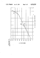
- FIG. 2 is a graph illustrating the nonlinear relationships between the register count and temperature and the piecewise linear relationship used to approximate the nonlinear relationship
- FIGS. 3-4 are logical flow diagrams illustrating the logical operations performed by the controller in converting the register count to temperature utilizing a piecewise linear coversion
- FIGS. 4-6 are logical flow diagrams illustrating the logical operations performed by the controller utilizing the pulse width modulation analog-to-digital conversion
- FIGS. 7-9 are logical flow diagrams illustrating the logical operations performed by the heating element status monitoring circuitry.
- a microprocessor controlled temperature control system generally designated by the reference numeral 10.
- the temperature control system 10 utilizes a microprocessor 12 to perform the basic control functions as will be described in subsequent portions of the specification.
- the microprocessor 12 is a Type 7516 microprocessor that is manufactured by NEC and others.
- the Type 7516 microprocessor was selected because it has the capability of providing a variable pulse width square wave output signal that is useful for making the temperature measurement, as will be subsequently described; however, a microprocessor without such a feature may also be used and the variable square wave may be provided by other circuitry, such as, for example, an interrupt timer.
- the system 10 controls the temperature within an appliance such as an oven 14 which may be an electric or a gas oven or other similar appliance.
- the oven 14 is illustrated as an electric oven having a broiling heating element 16 and a baking heating element 18; but it should be understood that different configurations of elements could be used and that the system is usable for controlling the temperature of appliances that are heated (or cooled) by various methods.
- the system according to the invention employs a thermistor 20 within the oven 14 that is electrically connected to a resistor 22 and a capacitor 24 and to one input of a comparator 26.
- the other input of the comparator 26 is connected to an integrating circuit comprising a resistor 28 and a capacitor 30 that integrates a variable pulse width square wave signal to provide an analog signal whose amplitude is compared by the comparator 26 with the amplitude of the signal at the junction of the resistor 22 and thermistor 20.
- Power is applied to the heating elements 16 and 18 by three relays 32, 34 and 36.
- the relay 32 has a contact armature 38 that selectively closes a circuit between one line of a power supply and one side of the heating elements 16 and 18.
- the relay 32 also has a coil 40 that is selectively energized by a transistor 42 under the control of the microprocessor 12 to selectively connect the heating elements 16 and 18 to one side of the power line.
- the relay 34 has an armature contact 44 that is actuated by a coil 46 and selectively connects the other side of the power line to the other side of the baking element 18.
- the coil 46 is energized by a transistor 48 under the control of the microprocessor 12.
- the relay 36 has an armature contact 50 that is controlled by a coil 52 in order to selectively connect the other side of the broiling element to the power line to selectively energize the element 16.
- the coil 52 is energized by a transistor 54 under the control of the microprocessor 12. While the switching devices that control the operaration of the heating elements 16 and 18 have been illustrated as the relays 32, 34 and 36, it should be understood that other switching devices including semiconductor devices such as thyristors or other electrical switching devices could also be used. Also, it should be understood that the switching devices could be replaced by other control devices such as gas valves that are controlled by the transistors 42, 48 and 54 if the controller were used in a gas oven environment.
- a monitoring circuit 60 comprising three transistors 62, 64 and 66 that monitor the voltage on the load side of the relays 32, 34 and 36.
- a rectifier/filter circuit comprising a resistor 68, a capacitor 70 and a diode 72 is used to rectify the signal applied to the base of the transistor 62.
- a rectifier/filter circuit comprising a resistor 74, a capacitor 76 and a diode 78 is provided for the transistor 64, and a similar circuit comprising a resistor 80, a capacitor 82 and a diode 84 is provided for the transistor 62.
- Resistors 86, 88 and 90 serve as collector load resistors for the transistors 62, 64 and 66, respectively, and resistors 92, 94 and 96 serve to isolate the monitoring circuitry 60 from the high voltages present at the contacts of the relays 32, 34 and 36, respectively.
- a display 100 is coupled to the microprocessor 12 and serves to display various functions normally displayed by appliances such as time of day, the operational status of the appliance, for example, whether the appliance is on or off or in a baking, broiling or self-cleaning mode of operation.
- a temperature/function selector 102 is also provided to permit the user to enter operational instructions into the system.
- the selector 102 may be a keypad that permits the user to select a desired cooking temperature by entering that temperature via the keypad and to select other functions such as baking, broiling or self-cleaning by touching the appropriate keypads. Also, other instructions such as cooking time and cooking start and stop times may also be entered via the selector 102.
- the pulse width of the square wave at the PPO output of the microprocessor is dependent upon a count entered into the PPO register of the microprocessor.
- the count in the PPO register may vary over a large range depending on the range of pulse widths required, and in the present embodiment, the range of values in the PPO register will vary between 1000 and approximately 9,000.
- the variable pulse width square wave at the PPO terminal of the microprocessor 12 is a unit directional pulse, and consequently, when integrated by the resistor 28 and capacitor 30 provides a DC voltage whose amplitude is proportional to the pulse width of the square wave. This DC voltage is compared with the DC voltage present at the junction of the resistor 22 and the thermistor 20, and thus, the count in the PPO register corresponding to a particular temperature can be determined.
- the resistor 22 and the thermistor 20 form a voltage divider and hence, the voltage at the junction of the resistor 22 and the thermistor 20 is a function of the resistance of the thermistor 20 which is related to the temperature in the oven 14.
- a temperature versus PPO register value plot can be made.
- the plot can be made for a single temperature sensor such as the thermistor 20 and resistor 22 or for additional temperature sensors, such as, for example, meat and candy thermometers.
- additional sensors can then be monitored by successively comparing the integrated square wave signal with the various sensor signals and determining the register count that provides the integrated square wave signal that corresponds to each sensor signal. Temperature can then be determined from the appropriate temperature versus PPO register value plot.
- FIG. 2 A typical plot is illustrated in FIG. 2.
- the temperature versus PPO register value for various temperatures is illustrated by the curved line 110 in FIG. 2.
- the shape of the curved line 110 can be approximated in a piecewise linear fashion by two straight lines 112 and 114 whose equations can readily be calculated.
- the slope of the line is equal to: -(Y max -Y min )/(X max -X min ), where X max , Y max and X min , Y min correspond to the end points of the line or to any conveniently spaced coordinates on the line.
- the equations for the two lines 112 and 114 can be readily ascertained and the appropriate equation used in the corresponding range of counts of the PPO register.
- the count in the PWM register is not less than 2668, a determination is made as to whether it is between 2668 and 8144. If it is within the aforesaid range, that indicates that the count is within the piecewise range spanned by the line segment 112 (FIG. 2) and the constants designed as Range 1 and corresponding to the constants for the line 112 are utilized. If the count is not within the 2668 to 8144 range, a determination is made as to whether the count is between 8143 and 8950. If not, this is indicative that the sensor 20 is open and an open sensor error flag is set. If the count is within the above range, then the set of constants for the line segment 114, as defined by Range 2, are utilized in making the temperature determination.
- Range 1 the temperature is equal to M1 ⁇ PWM+B1 where PWM is the count in the PPO register and M1 and B1 are the slope and Y-axis intercept of the line segment 112.
- M1 and B1 are the slope and Y-axis intercept of the line segment 112.
- M2 and B2 are the slope and Y-axis intercept of the line segment 114.
- the temperature thus calculated is the temperature that corresponds to the count PWM present in the PPO register, and any offset that is desired is added to the temperature based on the desired offset and whether the oven is in a self-cleaning mode.
- the offset temperature corresponding to the count PWM in the PPO register is determined. However, this temperature must be related to the temperature being read by the sensor 20. If the temperature determined from the PWM register is substantially equal to the temperature being read by the sensor 20 within a predetermined increment (which in the present embodiment corresponds to a value of 1 in the Seek Table, as is discussed in conjunction with FIG. 6), then the temperature determined from the PWM register is considered to be equal to the sensed temperature and is transferred to a Fahrenheit holding register. If not, the temperature is again read by a READ T1 algorithm as illustrated in FIGS. 5 and 6.
- the count is incremented to provide a square wave whose pulse width is periodically stepped in variable size increments to provide a stepped analog signal at the output of the integrator that is compared with the signal from the temperature sensor 20.
- This is accomplished by a seek routine that first selects a value for the PWM count that corresponds to a temperature of 75° F. (nominally room temperature), and compares the integrated analog voltage with the voltage from the sensor. If the integrated voltage is low, the pulse width of the square wave is increased by a predetermined amount and the comparison is again made. If the integrated voltage is still low, the pulse width is again increased by the same amount and the comparison again made.
- the process is repeated until the integrated voltage exceeds the voltage from the sensor. At this point, the pulse width is decreased by an amount equal to one-half the increment by which the PWM count in the PWM counter was last increased and the comparison is again made. If the incremented voltage is still above the voltage from the sensor, the count PWM is again decremented by the same amount until the integrated voltage drops below the voltage from the sensor. When this occurs, the count PWM is again increased by an amount equal to one-half of the previous decrement and the process is repeated so that the integrated voltage fluctuates about the voltage from the temperature sensor in ever decreasing increments until the integrated voltage approaches the sensed voltage by a predetermined increment.
- the seek algorithm utilizes the following values for incrementing the PWM count, as illustrated in the PWM Seek Table below:
- the system first loads a count into the PWM counter that corresponds to a temperature of 75° Fahrenheit, as determined by the appropriate line segment equation.
- a pointer is positioned at the largest increment, 256 counts, of the PWM Seek Table.
- the output of the comparator 26 is checked, and if the value of the integrated square wave voltage is low, as indicated by a low output of the comparator 26, an increment of 256 counts is added to the PWM register count.
- the output of the comparator 26 is checked again, and if the output of the comparator 26 has not gone high, a count of 256 is again added until the output of the comparator changes state and goes low.
- the routine transfers to the READ T1 subroutine that increments or decrements the pulse width until the temperature is determined as illustrated in FIGS. 5 and 6.
- the output of the comparator 26 is monitored after each comparison to determine whether the comparator has changed state. A change of state is indicated by the output of the comparator being high together with the occurrence of a high seek direction bit (positive incrementation) or the output of the comparator not being high together with a low seek direction bit (decrementation of the counter).
- FIGS. 1 The system illustrated in FIGS.
- 5 and 6 utilizes a search counter to count the number of comparisons that are made between occurrences of changes of state of the comparator 26.
- the system counts the number of comparisons that are made without the occurrence of a change of state. If more than eight comparisons are made without the occurrence of a change of state, the Seek Table pointer is incremented by one line to increase the amount that the integrated voltage is stepped. This is accomplished by loading an 8 into the search counter and decrementing it each time a comparison without a change of state occurs, and increasing the size of the stepped increment when the search register count reaches zero.
- the relays 32, 34 and 36 are controlled by the transistors 42, 48 and 54 under the control of the microprocessor 12 that selectively generates a high level or low level signal on each of three lines 110, 112 and 114 that are connected to the base electrodes of the transistors 42, 48 and 54, respectively. If the state of the signal on any one of the lines 110, 112 and 114 is low, the corresponding relay 32, 34 or 36 is not energized. Similarly, if the signal on any of the lines 110, 112 or 114 is high, then the corresponding one of the relays 32, 34 and 36 is energized.
- the status of the contacts of the relays is monitored by a monitoring circuit 60 that is coupled to the output contacts of the three relays to determine whether the relay contacts are open or closed. Because the contacts of the three relays switch high voltage, high power circuits, isolation must be provided between the relay contacts and the monitoring circuit 60 to avoid damage to the monitoring circuit 60 and possibility of electric shock to the user. This is accomplished by the three isolation resistors 92, 94 and 96 which each have a resistance of on the order of 4 megohms The resistors 92, 94 and 96 cooperate with resistors 68, 74 and 80, respectively, to form a voltage divider to reduce the voltages applied to the bases of the transistors 62, 64 and 66 to a low level.
- the resistance of each of the resistors 68, 74 and 80 is on the order of 100 kilohms so that the voltage present at the contact of the relays is divided by a factor of approximately 40 before being applied to the monitoring circuit 60.
- a high value for the resistance of the resistors 92, 94 and 96 was chosen so that the maximum current that could flow from the relay contacts to the monitoring circuit 60 would be limited to a safe value.
- the resistors 92, 94 and 96 are illustrated as single resistors in FIG. 1, two or more resistors connected in series could be used in place of a single resistor. For example, two 2-megohm resistors connected in series could be used in place of a 4-megohm resistor. Such an arrangement would have the advantage that if one of the resistors should short out, the other one of the resistors would still limit the maximum current that could be applied to the monitor 60 to a safe value.
- the voltage applied to the bases of the three transistors 62, 64 and 66 are rectified by the diodes 72, 78 and 84 and filtered by the capacitors 70, 76 and 82 to provide a DC voltage at the bases of the respective transistors 62, 64 and 66 when an AC voltage is present at the monitored contacts of the relays 32, 34 and 36.
- the appropriate transistors 62, 64 and 66 will conduct and cause the output at its collector to go low.
- the outputs of the transistors 62, 64 and 66 are applied to the microprocessor 12 via lines 116, 118 and 120.
- a low signal on any one of the lines 116, 118 and 120 will indicate that there is voltage present on the contact being monitored.
- the monitor signal on the corresponding one of the lines 116, 118 and 120 must be low and vice versa. Otherwise, a flag indicating a fault is set.
- the signal on the line 110 controls the application of power to the ends of the broiling element 16 and the baking element 18 that are connected in common.
- the signal on the line 112 controls the application of power to the other end of the baking element 18 and the signal on the line 114 controls the application of power to the other end of the broiling element 16.
- control signals there are four possible combinations of control signals that can be applied to the lines 114, 112 and 110 by the microprocessor 12. These correspond to both elements being off, only the bake element 18 being on, only the broil element 16 being on, and both elements being on. With all elements being off, all three signals on the lines 114, 112 and 110 will be low or zero providing a status reading of 000 when reading the status of the signals on the lines 114, 112 and 110, respectively. If there is no fault in the system, because of the phase inversion of the transistors 62, 64 and 66, the monitored signals on the lines 116, 118 and 120 should be 111 (7). Any other reading on the lines 116, 118 and 120 when the status of the lines 110, 112 and 114 is 000 would be indicative of a fault.
- the monitoring of the status of the relays is illustrated in the flow charts shown in FIGS. 7-9.
- the relays are timed to turn on in sequence, with the turn on sequence being relay 32, relay 34 and relay 36.
- the turn off sequence is relay 36, relay 34 and relay 32.
- a 250 millisecond delay is provided between the turn on of individual relays to increase relay life.
- the delay is provided by a relay delay counter (FIG. 7).
- a determination is made as to whether the relay delay counter is stable and no reading is made until it becomes stable at the end of the 250 millisecond delay time. If it is stable, a determination is made as to whether the inhibit flag has been set.
- the inhibit flag prevents the status of the relays from being monitored until the AC waveform of the signal being switched by the relays is at its peak. Thus, the inhibit flag is reset by the peak of the AC waveform to permit the reading to be taken.
- the relay monitor signal on the lines 120, 118 and 116 is obtained and a determination is made as to whether its value is equal to 7 (111). A determination is made as to whether the relay control signal on the lines 114, 112 and 110 is equal to 000 and, if so, this is a proper condition and any fault flag is reset and the routine is exited. If the relay control status is not zero, a fault flag is set.
- the value of the relay monitor signal on the lines 120, 118 and 116 were not equal to 7, then the value would be determined by the subroutine RCM2 (FIG. 8).
Abstract
Description
______________________________________
PWM SEEK TABLE
______________________________________
256
128
64
32
16
4
2
1
______________________________________
Claims (20)
Priority Applications (1)
| Application Number | Priority Date | Filing Date | Title |
|---|---|---|---|
| US07/311,705 US4933535A (en) | 1989-02-15 | 1989-02-15 | Piecewise linear temperature controller utilizing pulse width modulation |
Applications Claiming Priority (1)
| Application Number | Priority Date | Filing Date | Title |
|---|---|---|---|
| US07/311,705 US4933535A (en) | 1989-02-15 | 1989-02-15 | Piecewise linear temperature controller utilizing pulse width modulation |
Publications (1)
| Publication Number | Publication Date |
|---|---|
| US4933535A true US4933535A (en) | 1990-06-12 |
Family
ID=23208094
Family Applications (1)
| Application Number | Title | Priority Date | Filing Date |
|---|---|---|---|
| US07/311,705 Expired - Fee Related US4933535A (en) | 1989-02-15 | 1989-02-15 | Piecewise linear temperature controller utilizing pulse width modulation |
Country Status (1)
| Country | Link |
|---|---|
| US (1) | US4933535A (en) |
Cited By (12)
| Publication number | Priority date | Publication date | Assignee | Title |
|---|---|---|---|---|
| US5504305A (en) * | 1990-12-13 | 1996-04-02 | Cooper Industries, Inc. | Temperature control device for soldering and unsoldering equipment |
| US5564831A (en) * | 1989-08-11 | 1996-10-15 | Whirlpool Corporation | Method and apparatus for detecting the temperature of an environment |
| US5613149A (en) * | 1991-12-06 | 1997-03-18 | National Semiconductor Corporation | Integrated data processing system utilizing successive approximation analog to digital conversion and PWM for parallel disconnect |
| WO1998002721A2 (en) * | 1996-07-01 | 1998-01-22 | Integrated Sensor Solutions | Calibration of a sensor with temperature variations |
| US20030093189A1 (en) * | 2001-10-30 | 2003-05-15 | Takayoshi Honda | Electronic control apparatus |
| US20040122559A1 (en) * | 1998-03-23 | 2004-06-24 | Cepheid | System and method for temperature control |
| US20040234376A1 (en) * | 2003-05-19 | 2004-11-25 | Marando Eileen M. | Piecewise linear control of the duty cycle of a pulse width modulated signal |
| WO2007086625A1 (en) * | 2006-01-26 | 2007-08-02 | Jong-Jin Kil | Safety magnetic field-free temperature controller |
| US20110190761A1 (en) * | 2006-09-28 | 2011-08-04 | Covidien Ag | Temperature Sensing Return Electrode Pad |
| US20110220636A1 (en) * | 2010-03-09 | 2011-09-15 | Bsh Home Appliances Corporation | Frequency-modulated electric element control |
| US8235980B2 (en) | 2007-05-07 | 2012-08-07 | Tyco Healthcare Group Lp | Electrosurgical system for measuring contact quality of a return pad |
| US8430873B2 (en) | 2007-08-01 | 2013-04-30 | Covidien Lp | System and method for return electrode monitoring |
Citations (5)
| Publication number | Priority date | Publication date | Assignee | Title |
|---|---|---|---|---|
| US3586830A (en) * | 1968-11-29 | 1971-06-22 | Coltron Ind | Logical control for discretely metering energy to thermal systems incorporating apparatus and methods for simulating time related temperatures |
| US3878358A (en) * | 1972-11-16 | 1975-04-15 | Xerox Corp | Digital power control |
| US4113391A (en) * | 1975-10-27 | 1978-09-12 | Kabushiki Kaisha Suwa Seikosha | Method for controlling voltage and providing temperature compensation in a thermal printer |
| US4374321A (en) * | 1979-12-11 | 1983-02-15 | International Business Machines Corporation | Automatic temperature controller for an electrophotographic apparatus fuser and method therefor |
| US4614860A (en) * | 1984-03-30 | 1986-09-30 | Societe Kativois | Process and device for the anticipatory self-adapting regulation of a procedure |
-
1989
- 1989-02-15 US US07/311,705 patent/US4933535A/en not_active Expired - Fee Related
Patent Citations (5)
| Publication number | Priority date | Publication date | Assignee | Title |
|---|---|---|---|---|
| US3586830A (en) * | 1968-11-29 | 1971-06-22 | Coltron Ind | Logical control for discretely metering energy to thermal systems incorporating apparatus and methods for simulating time related temperatures |
| US3878358A (en) * | 1972-11-16 | 1975-04-15 | Xerox Corp | Digital power control |
| US4113391A (en) * | 1975-10-27 | 1978-09-12 | Kabushiki Kaisha Suwa Seikosha | Method for controlling voltage and providing temperature compensation in a thermal printer |
| US4374321A (en) * | 1979-12-11 | 1983-02-15 | International Business Machines Corporation | Automatic temperature controller for an electrophotographic apparatus fuser and method therefor |
| US4614860A (en) * | 1984-03-30 | 1986-09-30 | Societe Kativois | Process and device for the anticipatory self-adapting regulation of a procedure |
Cited By (21)
| Publication number | Priority date | Publication date | Assignee | Title |
|---|---|---|---|---|
| US5564831A (en) * | 1989-08-11 | 1996-10-15 | Whirlpool Corporation | Method and apparatus for detecting the temperature of an environment |
| US5504305A (en) * | 1990-12-13 | 1996-04-02 | Cooper Industries, Inc. | Temperature control device for soldering and unsoldering equipment |
| US5613149A (en) * | 1991-12-06 | 1997-03-18 | National Semiconductor Corporation | Integrated data processing system utilizing successive approximation analog to digital conversion and PWM for parallel disconnect |
| WO1998002721A2 (en) * | 1996-07-01 | 1998-01-22 | Integrated Sensor Solutions | Calibration of a sensor with temperature variations |
| WO1998002721A3 (en) * | 1996-07-01 | 1998-02-19 | Integrated Sensor Solutions | Calibration of a sensor with temperature variations |
| US5902925A (en) * | 1996-07-01 | 1999-05-11 | Integrated Sensor Solutions | System and method for high accuracy calibration of a sensor for offset and sensitivity variation with temperature |
| US20040122559A1 (en) * | 1998-03-23 | 2004-06-24 | Cepheid | System and method for temperature control |
| US7188001B2 (en) | 1998-03-23 | 2007-03-06 | Cepheid | System and method for temperature control |
| US20030093189A1 (en) * | 2001-10-30 | 2003-05-15 | Takayoshi Honda | Electronic control apparatus |
| US7210055B2 (en) * | 2001-10-30 | 2007-04-24 | Denso Corporation | Electronic control apparatus |
| US20060193729A1 (en) * | 2003-05-19 | 2006-08-31 | Standard Microsystems Corporation | Generating a PWM signal dependent on a duty cycle having a piecewise linear relationship with temperature |
| US7029239B2 (en) * | 2003-05-19 | 2006-04-18 | Standard Microsystems Corporation | Piecewise linear control of the duty cycle of a pulse width modulated signal |
| US20040234376A1 (en) * | 2003-05-19 | 2004-11-25 | Marando Eileen M. | Piecewise linear control of the duty cycle of a pulse width modulated signal |
| US8662858B2 (en) * | 2003-05-19 | 2014-03-04 | Standard Microsystems Corporation | Generating a PWM signal dependent on a duty cycle having a piecewise linear relationship with temperature |
| WO2007086625A1 (en) * | 2006-01-26 | 2007-08-02 | Jong-Jin Kil | Safety magnetic field-free temperature controller |
| US20110190761A1 (en) * | 2006-09-28 | 2011-08-04 | Covidien Ag | Temperature Sensing Return Electrode Pad |
| US8216222B2 (en) * | 2006-09-28 | 2012-07-10 | Covidien Ag | Temperature sensing return electrode pad |
| US8235980B2 (en) | 2007-05-07 | 2012-08-07 | Tyco Healthcare Group Lp | Electrosurgical system for measuring contact quality of a return pad |
| US8430873B2 (en) | 2007-08-01 | 2013-04-30 | Covidien Lp | System and method for return electrode monitoring |
| US20110220636A1 (en) * | 2010-03-09 | 2011-09-15 | Bsh Home Appliances Corporation | Frequency-modulated electric element control |
| US8420986B2 (en) | 2010-03-09 | 2013-04-16 | Bsh Home Appliances Corporation | Frequency-modulated electric element control |
Similar Documents
| Publication | Publication Date | Title |
|---|---|---|
| US4933535A (en) | Piecewise linear temperature controller utilizing pulse width modulation | |
| US4782445A (en) | Control apparatus for cooking apparatus | |
| AU708566B2 (en) | Electronic thermostat control unit and its use in multi-point temperature controller for refrigeration and heating systems | |
| US4035787A (en) | Food temperature responsive control apparatus | |
| US4507546A (en) | Control circuit responsive to a component's varying resistance | |
| AU3166099A (en) | Multipoint digital temperature controller | |
| US9304049B2 (en) | Temperature measuring device, electric appliance having such a temperature measuring device and method for temperature measuring | |
| US4338511A (en) | Electronic thermostat equipped with an energy-saving device | |
| US6141198A (en) | Solid state overload relay | |
| US3924101A (en) | Oven temperature sensing circuitry | |
| KR950010382B1 (en) | Control circuit for a refrigerator combined with a microwave oven | |
| US3733463A (en) | Temperature control system with a pulse width modulated bridge | |
| US3684172A (en) | Thermocouple temperature control system | |
| US4296632A (en) | Temperature-to-frequency conversion apparatus | |
| US5528017A (en) | Electronic thermostat for an oven | |
| US4534406A (en) | Thermostat | |
| US3632985A (en) | Thermocouple bridge temperature control | |
| US3231802A (en) | Indicating controller | |
| US3428785A (en) | Solid state oven temperature control | |
| US2645744A (en) | Dual limit control circuit | |
| US4323861A (en) | Oscillator circuit for controlling the power level of a microwave oven | |
| US4459467A (en) | Temperature controlled oven with multiple preset temperatures | |
| US3546434A (en) | Regulating system for heating elements | |
| US3937922A (en) | Control system | |
| KR100298086B1 (en) | Electronic Thermostat Control of Multipoint Temperature Controllers for Refrigeration and Heating Systems and How to Use Them |
Legal Events
| Date | Code | Title | Description |
|---|---|---|---|
| AS | Assignment |
Owner name: HARPER-WYMAN COMPANY, ILLINOIS Free format text: ASSIGNMENT OF ASSIGNORS INTEREST.;ASSIGNOR:ZABINSKI, JOHN E.;REEL/FRAME:005042/0863 Effective date: 19890131 |
|
| FPAY | Fee payment |
Year of fee payment: 4 |
|
| FPAY | Fee payment |
Year of fee payment: 8 |
|
| REMI | Maintenance fee reminder mailed | ||
| LAPS | Lapse for failure to pay maintenance fees | ||
| STCH | Information on status: patent discontinuation |
Free format text: PATENT EXPIRED DUE TO NONPAYMENT OF MAINTENANCE FEES UNDER 37 CFR 1.362 |
|
| AS | Assignment |
Owner name: APPLIANCE CONTROLS GROUP, INC., ILLINOIS Free format text: ASSIGNMENT OF ASSIGNORS INTEREST;ASSIGNOR:HARPER-WYMAN COMPANY;REEL/FRAME:013067/0292 Effective date: 20020531 |
|
| AS | Assignment |
Owner name: TRANSAMERICA BUSINESS CAPITAL CORPORATION, AS AGEN Free format text: SECURITY INTEREST;ASSIGNOR:APPLIANCE CONTROLS GROUP, INC.;REEL/FRAME:013081/0647 Effective date: 20020621 |
|
| AS | Assignment |
Owner name: HILCO CAPITAL LP, ILLINOIS Free format text: ASSIGNMENT OF ASSIGNORS INTEREST;ASSIGNOR:APPLIANCE CONTROLS GROUP, INC.;REEL/FRAME:013146/0196 Effective date: 20020726 Owner name: HILCO CAPITAL LP, ILLINOIS Free format text: SECURITY AGREEMENT;ASSIGNOR:APPLIANCE CONTROLS GROUP, INC.;REEL/FRAME:013146/0180 Effective date: 20020726 |
|
| FP | Lapsed due to failure to pay maintenance fee |
Effective date: 20020612 |
|
| AS | Assignment |
Owner name: BURNER SYSTEMS INTERNATIONAL, INC., TENNESSEE Free format text: ASSIGNMENT OF ASSIGNORS INTEREST;ASSIGNORS:APPLIANCE CONTROLS GROUP HOLDINGS, INC.;APPLIANCE CONTROLS GROUP, INC.;REEL/FRAME:014943/0183 Effective date: 20040726 |
|
| AS | Assignment |
Owner name: JPMORGAN CHASE BANK, NEW YORK Free format text: SECURITY AGREEMENT;ASSIGNOR:BURNER SYSTEMS INTERNATIONAL, INC.;REEL/FRAME:014964/0774 Effective date: 20040726 |
|
| AS | Assignment |
Owner name: APPLIANCE CONTROLS GROUP, INC., ILLINOIS Free format text: ASSIGNMENT OF ASSIGNORS INTEREST;ASSIGNOR:HILCO CAPITAL, LP;REEL/FRAME:015676/0400 Effective date: 20040725 Owner name: APPLIANCE CONTROLS GROUP, INC., ILLINOIS Free format text: RELEASE OF SECURITY INTEREST;ASSIGNOR:HILCO CAPITAL, LP;REEL/FRAME:015676/0405 Effective date: 20040725 |