US4930855A - Wavelength multiplexing of lasers - Google Patents
Wavelength multiplexing of lasers Download PDFInfo
- Publication number
- US4930855A US4930855A US07/202,356 US20235688A US4930855A US 4930855 A US4930855 A US 4930855A US 20235688 A US20235688 A US 20235688A US 4930855 A US4930855 A US 4930855A
- Authority
- US
- United States
- Prior art keywords
- beams
- lasers
- diffraction grating
- colinear
- wavelength
- Prior art date
- Legal status (The legal status is an assumption and is not a legal conclusion. Google has not performed a legal analysis and makes no representation as to the accuracy of the status listed.)
- Expired - Lifetime
Links
Images


Classifications
-
- G—PHYSICS
- G02—OPTICS
- G02B—OPTICAL ELEMENTS, SYSTEMS OR APPARATUS
- G02B6/00—Light guides; Structural details of arrangements comprising light guides and other optical elements, e.g. couplings
- G02B6/24—Coupling light guides
- G02B6/42—Coupling light guides with opto-electronic elements
- G02B6/4201—Packages, e.g. shape, construction, internal or external details
- G02B6/4204—Packages, e.g. shape, construction, internal or external details the coupling comprising intermediate optical elements, e.g. lenses, holograms
- G02B6/4215—Packages, e.g. shape, construction, internal or external details the coupling comprising intermediate optical elements, e.g. lenses, holograms the intermediate optical elements being wavelength selective optical elements, e.g. variable wavelength optical modules or wavelength lockers
-
- G—PHYSICS
- G02—OPTICS
- G02B—OPTICAL ELEMENTS, SYSTEMS OR APPARATUS
- G02B6/00—Light guides; Structural details of arrangements comprising light guides and other optical elements, e.g. couplings
- G02B6/24—Coupling light guides
- G02B6/26—Optical coupling means
- G02B6/28—Optical coupling means having data bus means, i.e. plural waveguides interconnected and providing an inherently bidirectional system by mixing and splitting signals
- G02B6/293—Optical coupling means having data bus means, i.e. plural waveguides interconnected and providing an inherently bidirectional system by mixing and splitting signals with wavelength selective means
- G02B6/29304—Optical coupling means having data bus means, i.e. plural waveguides interconnected and providing an inherently bidirectional system by mixing and splitting signals with wavelength selective means operating by diffraction, e.g. grating
- G02B6/29305—Optical coupling means having data bus means, i.e. plural waveguides interconnected and providing an inherently bidirectional system by mixing and splitting signals with wavelength selective means operating by diffraction, e.g. grating as bulk element, i.e. free space arrangement external to a light guide
- G02B6/2931—Diffractive element operating in reflection
-
- G—PHYSICS
- G02—OPTICS
- G02B—OPTICAL ELEMENTS, SYSTEMS OR APPARATUS
- G02B6/00—Light guides; Structural details of arrangements comprising light guides and other optical elements, e.g. couplings
- G02B6/24—Coupling light guides
- G02B6/26—Optical coupling means
- G02B6/28—Optical coupling means having data bus means, i.e. plural waveguides interconnected and providing an inherently bidirectional system by mixing and splitting signals
- G02B6/293—Optical coupling means having data bus means, i.e. plural waveguides interconnected and providing an inherently bidirectional system by mixing and splitting signals with wavelength selective means
- G02B6/29304—Optical coupling means having data bus means, i.e. plural waveguides interconnected and providing an inherently bidirectional system by mixing and splitting signals with wavelength selective means operating by diffraction, e.g. grating
- G02B6/29305—Optical coupling means having data bus means, i.e. plural waveguides interconnected and providing an inherently bidirectional system by mixing and splitting signals with wavelength selective means operating by diffraction, e.g. grating as bulk element, i.e. free space arrangement external to a light guide
- G02B6/29313—Optical coupling means having data bus means, i.e. plural waveguides interconnected and providing an inherently bidirectional system by mixing and splitting signals with wavelength selective means operating by diffraction, e.g. grating as bulk element, i.e. free space arrangement external to a light guide characterised by means for controlling the position or direction of light incident to or leaving the diffractive element, e.g. for varying the wavelength response
-
- G—PHYSICS
- G02—OPTICS
- G02B—OPTICAL ELEMENTS, SYSTEMS OR APPARATUS
- G02B6/00—Light guides; Structural details of arrangements comprising light guides and other optical elements, e.g. couplings
- G02B6/24—Coupling light guides
- G02B6/26—Optical coupling means
- G02B6/28—Optical coupling means having data bus means, i.e. plural waveguides interconnected and providing an inherently bidirectional system by mixing and splitting signals
- G02B6/293—Optical coupling means having data bus means, i.e. plural waveguides interconnected and providing an inherently bidirectional system by mixing and splitting signals with wavelength selective means
- G02B6/29379—Optical coupling means having data bus means, i.e. plural waveguides interconnected and providing an inherently bidirectional system by mixing and splitting signals with wavelength selective means characterised by the function or use of the complete device
- G02B6/2938—Optical coupling means having data bus means, i.e. plural waveguides interconnected and providing an inherently bidirectional system by mixing and splitting signals with wavelength selective means characterised by the function or use of the complete device for multiplexing or demultiplexing, i.e. combining or separating wavelengths, e.g. 1xN, NxM
Definitions
- This invention relates generally to laser communication systems and, more particularly, to techniques for increasing the efficiency of communication by lasers.
- Semiconductor diode lasers are attractive for communications in space because of their compactness and relatively low power consumption. However, for distances of about 40,000 km or more, an average laser power of at least 300 mW is needed to obtain communication rates in the 1 Gbit/s (gigabit per second) range. Single diode lasers are not yet available at this power level. Even with the use of coherent laser arrays to increase power output, there is still a need for a new approach to increase the bandwidth, versatility and reliability of the communication system. Present technology is limited to communications rates of about 1 Gbit/s.
- the present invention resides in a laser wavelength multiplexing and demultiplexing system to increase the power of a communications beam and provide a practically colinear beam from a plurality of single-mode lasers.
- the apparatus of the invention as viewed at a transmission end of a communication system, comprises a plurality of single-mode diode lasers operating at different selected wavelengths, and means for combining the outputs of the lasers to produce a nearly diffraction-limited and colinear beam having an average power approximating the sum of the outputs of the individual lasers.
- the apparatus also includes a dispersive element that provides a deflection angle dependent on the wavelength of the incident light.
- a dispersive element that provides a deflection angle dependent on the wavelength of the incident light.
- Such an element may be a diffraction grating, for example.
- the means for combining the outputs of the lasers includes means for directing the outputs onto the dispersive element at angles of incidence that correspond to the deflection angles provided by the dispersive effect of the element. Therefore, the dispersive element produces a parallel, colinear beam from the plurality of non-parallel incident beams of different wavelengths.
- pairs of laser beams are combined by means of reflective roof prisms.
- Each prism produces a combined output beam from two input beams. Then the prism output beams can be combined until a single composite beam is obtained. The single output beam impinges on a diffraction grating to effect the desired dispersion along colinear optical axes.
- the laser beams are combined by means of multiple optical fibers grouped together.
- the multiple outputs are focused onto a diffraction grating and diffracted along coincident paths.
- the multiple laser beams are arranged to enter a telescope eyepiece lens at a wide range of angles. After passing through the eyepiece lens and a telescope objective lens, the beams are collimated but impinge on the diffraction grating at slightly different angles, which are selected to provide identical diffraction angles and colinear output beams.
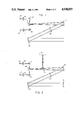
- FIG. 1 is a schematic diagram of apparatus for wavelength multiplexing multiple outputs from multiple semiconductor diode lasers
- FIG. 2 is a schematic diagram similar to FIG. 1, and also showing additional elements to demonstrate the colinearity and nearly diffraction-limited quality of the output beams from the lasers;
- FIG. 3 is a fragmentary schematic view illustrating the application of the same multiplexing principle to more than two diode lasers
- FIG. 4 is a schematic view of an alternative embodiment of the invention.
- FIG. 5 is a schematic view of another embodiment of a wavelength multiplexer in accordance with the invention.
- FIG. 6 is a schematic view of a wavelength demultiplexer similar in principle to the multiplexer of FIG. 6;
- FIG. 7 is a schematic view of a wavelength control system for use in conjunction with the multiplexer of the invention.
- the present invention is principally concerned with a technique for combining multiple laser beams into a single colinear beam of greater power.
- the principal application of this technique is in space communications by optical beams, using injection diode lasers as a light source.
- a single diode laser lacks the power needed for long-distance communication in space.
- Combining multiple lasers to produce a more powerful beam with perfect phase coherency has well known difficulties, but coherent arrays have been produced. Nevertheless, there is still a need to combine diode laser beams for greater total beam power.
- the use of wavelength multiplexing offers the possibility of combining multiple beams to produce a more powerful beam, and utilizing the separate wavelengths as separate communications channels.
- multiple diode lasers operating at different wavelengths are directed onto a dispersive element at appropriate angles to produce a set of output beams that are practically coincident or colinear.
- FIG. 1 shows by way of example a pair of diode lasers, indicated by reference numeral 10, having outputs focused by corresponding lenses 12 onto the reflective surfaces of a roof reflector or roof prism 16. by way of turning mirrors 14.
- the roof prism 16 reflects both beams along a generally identical path, although the two beams are still distinguishable by having slightly different angular directions, determined by the selected orientations of the turning mirrors 14 and the roof prism 16.
- the beams are reflected by another turning mirror 18, which plays no part in the invention other than rendering the apparatus more compact.
- the beams pass through a collimating lens 20 and are incident on a diffraction grating 22.
- the relative angular directions of the two beams were selected with a knowledge of the effect of the diffraction grating 22 on the incident beams.
- a diffraction grating provides an angle of diffraction that is dependent on the wavelength of the incident light.
- different wavelengths will be deflected through different angles by the diffraction grating 22, and if the angles of incidence are properly chosen in relation to the wavelengths, the output beams from the diffraction grating will be practically colinear, at least with respect to the plane of the diffraction grating.
- ⁇ i and ⁇ d are measured from the normal direction, ⁇ is the wavelength and d is the line spacing of the grating. Since the desired mode of operation of the grating is with a common angle of diffraction, a significant quantity is the angular beam spread due to the grating, for a single mode laser. This can be obtained by differentiating and rearranging the above equation, to obtain:
- the angular spread due to the effect of the grating on a single laser beam is 2.5 microradians, which is negligible when compared with the effect of normal diffraction on a beam of about three centimeters diameter.
- angles of incidence are determined not only by the various mirror angles associated with the separate laser beams, but also by the magnification of lenses interposed between the diode lasers and the diffraction grating 22.
- the relative angular directions of the separated laser beams may be relatively widely spaced near the diode lasers, and then reduced to the appropriate angular separations by the action of one or more lenses prior to reaching the diffraction grating 22.
- FIG. 2 shows the additional apparatus needed to demonstrate the colinearity and diffraction-limited quality of the output beam from the diffraction grating 22.
- a retromirror 24 is positioned in the path of the output beam from the grating 22. The output beam is reflected back along its original path, through the diffraction grating 22 and the turning mirror 20, until it reaches a beam-splitting mirror 26 located between the turning mirror 18 and the roof prism 16. The return beam reflected from the beam-splitting mirror is focused onto an image plane 28. Any angular errors in the colinearity of the output beam will be indicated by the position of the beam images on the image plane. In short, the image plane 28 permits analysis of the output beam from the apparatus.
- four diode lasers 10' may be combined using three roof prisms 18', two of which are used to combine two separate pairs of laser outputs, and the third of which is used to combine the outputs of the first two prisms. It will be apparent that the same technique can be extended to combine larger numbers of diode lasers into a single colinear output beam.
- FIG. 4 shows another embodiment of the invention, in which multiple diode lasers, here indicated at 30, are combined by means of single-mode optical fibers 32, the ends of which terminate in a focal plane 34, and provide a diverging set of beams, indicated at 36.
- the beams 36 pass through a collimating lens 38, which directs the beams onto a diffraction grating 40.
- the diffraction grating diffracts each of the beams through an angle dependent on the wavelength, and the angles of incidence are carefully chosen to provide identical angles of diffraction for each of the beams. Therefore, the output beams are colinear.
- the figure shows the output beams being reflected by a secondary mirror 42 and then a primary mirror 44, to emerge as a single beam 46.
- FIGS. 5 and 6 Another useful embodiment of the invention is shown in FIGS. 5 and 6.
- this embodiment employs a telescope eyepiece 50, into which the beams are directed from a plurality of diode lasers 52, through an equal plurality of focusing lenses 54.
- the lasers 52 are preferably arranged in a circular arc.
- the focusing lenses 54 are microscope objectives having sufficient numerical aperture to accommodate the divergence of each laser.
- a new waist of each beam is formed at the telescope eyepiece 50, and the beams then diverge by diffraction, to fill a telescope objective lens 56.
- a turning mirror 58 is positioned between the telescope eyepiece 50 and the objective lens 56.
- each beam emerges at a slightly different angle determined by its entrance angle to the eyepiece 50.
- the angles and component spacings are selected such that, when the beams reach the next component, a diffraction grating 60, they are exactly superimposed.
- the various wavelengths are diffracted by the grating 60 into a colinear beam because of the relationships between the angles of incidence, the groove spacing of the grating, and the wavelength values.
- the eyepiece lens 50 must have a very wide field of view, giving close to diffraction-limited performance at angles up to approximately 41 degrees from the optical axis. This angular spacing is demagnified by the telescope eyepiece and objective lenses, and the resulting angular differences are selected to produce the colinear beams after diffraction by the grating 60.
- the grating 60 can be designed to provide a diffraction efficiency of about 80 percent for all of the beams. This is the principal factor limiting the combining efficiency of the multiplexer of the invention.
- the same principle can be employed for demultiplexing a set of colinear or coincident beams of different wavelengths, as illustrated in FIG. 6.
- the colinear beams are first incident on a diffraction grating 60', from which they are diffracted at slightly different angles, depending on their wavelengths.
- the slightly diverging beams pass through a telescope objective lens 56', are reflected from a turning mirror 58', and then pass through a telescope eyepiece lens 50'.
- Multiple outputs from the eyepiece 50', one for each wavelength diverge into multiple focusing lenses 54', one for each communications channel, and are focused into corresponding optical detectors 62.
- turning mirrors 58, 58' are not essential to the invention, but are used to produce a more compact structure.
- a well known difficulty in the operation of diode lasers is that the temperature, and hence the wavelength, of a semiconductor diode may vary during its operation.
- the temperature of a diode junction is related to its junction voltage and current, and this characteristic may be employed to control the temperature, and hence the wavelength.
- One approach used in the apparatus of the invention is to periodically reduce the diode current to a well regulated level for a brief interval, such as three microseconds.
- the junction voltage is sampled during this time and compared to a reference voltage, as indicated at 64.
- the difference between the sampled voltage and the reference is used as an error signal, as indicated at 66, to adjust the current through a thermoelectric cooler 68 controlling the temperature of the diode laser.
- Such a control loop can maintain the wavelength output to within 0.0015% over a long period of time.
- the present invention represents a significant advance in the field of laser communication systems.
- the invention permits the convenient wavelength multiplexing of multiple diode lasers, to produce a practically colinear and diffraction-limited output beam.
- a similar structure can serve as a demultiplexing apparatus at the receiving end of a communications system.
- optical-wavelength employed in the claims is not intended to be limited to the visible light spectrum. Accordingly, the invention is not to be limited by the illustrative embodiments described in the specification.
Abstract
Description
sin θ.sub.i +sin θ.sub.d =λ/d,
dθ.sub.i =dλ/(d cos θ.sub.i).
Claims (16)
Priority Applications (1)
| Application Number | Priority Date | Filing Date | Title |
|---|---|---|---|
| US07/202,356 US4930855A (en) | 1988-06-06 | 1988-06-06 | Wavelength multiplexing of lasers |
Applications Claiming Priority (1)
| Application Number | Priority Date | Filing Date | Title |
|---|---|---|---|
| US07/202,356 US4930855A (en) | 1988-06-06 | 1988-06-06 | Wavelength multiplexing of lasers |
Publications (1)
| Publication Number | Publication Date |
|---|---|
| US4930855A true US4930855A (en) | 1990-06-05 |
Family
ID=22749545
Family Applications (1)
| Application Number | Title | Priority Date | Filing Date |
|---|---|---|---|
| US07/202,356 Expired - Lifetime US4930855A (en) | 1988-06-06 | 1988-06-06 | Wavelength multiplexing of lasers |
Country Status (1)
| Country | Link |
|---|---|
| US (1) | US4930855A (en) |
Cited By (36)
| Publication number | Priority date | Publication date | Assignee | Title |
|---|---|---|---|---|
| US6011885A (en) * | 1997-12-13 | 2000-01-04 | Lightchip, Inc. | Integrated bi-directional gradient refractive index wavelength division multiplexer |
| US6011884A (en) * | 1997-12-13 | 2000-01-04 | Lightchip, Inc. | Integrated bi-directional axial gradient refractive index/diffraction grating wavelength division multiplexer |
| US6108471A (en) * | 1998-11-17 | 2000-08-22 | Bayspec, Inc. | Compact double-pass wavelength multiplexer-demultiplexer having an increased number of channels |
| US6137933A (en) * | 1997-12-13 | 2000-10-24 | Lightchip, Inc. | Integrated bi-directional dual axial gradient refractive index/diffraction grating wavelength division multiplexer |
| US6236780B1 (en) | 1997-12-13 | 2001-05-22 | Light Chip, Inc. | Wavelength division multiplexing/demultiplexing devices using dual diffractive optic lenses |
| US6236666B1 (en) | 1996-05-17 | 2001-05-22 | Uab Research Foundation | Semiconductor laser with a superbroadband or multiline spectral output |
| US6243513B1 (en) | 1997-12-13 | 2001-06-05 | Lightchip, Inc. | Wavelength division multiplexing/demultiplexing devices using diffractive optic lenses |
| US6263135B1 (en) | 1997-12-13 | 2001-07-17 | Lightchip, Inc. | Wavelength division multiplexing/demultiplexing devices using high index of refraction crystalline lenses |
| US6271970B1 (en) | 1997-12-13 | 2001-08-07 | Lightchip, Inc. | Wavelength division multiplexing/demultiplexing devices using dual homogeneous refractive index lenses |
| US6275630B1 (en) | 1998-11-17 | 2001-08-14 | Bayspec, Inc. | Compact double-pass wavelength multiplexer-demultiplexer |
| US6289155B1 (en) | 1997-12-13 | 2001-09-11 | Lightchip, Inc. | Wavelength division multiplexing/demultiplexing devices using dual high index of refraction crystalline lenses |
| US6298182B1 (en) | 1997-12-13 | 2001-10-02 | Light Chip, Inc. | Wavelength division multiplexing/demultiplexing devices using polymer lenses |
| US6343169B1 (en) | 1999-02-25 | 2002-01-29 | Lightchip, Inc. | Ultra-dense wavelength division multiplexing/demultiplexing device |
| US6349103B1 (en) | 1997-05-07 | 2002-02-19 | Samsung Electronics Co., Ltd. | Cold-start wavelength-division-multiplexed optical transmission system |
| US6404945B1 (en) | 1997-12-13 | 2002-06-11 | Lightchip, Inc. | Wavelength division multiplexing/demultiplexing devices using homogeneous refractive index lenses |
| US6415073B1 (en) | 2000-04-10 | 2002-07-02 | Lightchip, Inc. | Wavelength division multiplexing/demultiplexing devices employing patterned optical components |
| US6423925B1 (en) | 2000-02-17 | 2002-07-23 | Universal Laser Systems, Inc. | Apparatus and method for combining multiple laser beams in laser material processing systems |
| US6434299B1 (en) | 1999-06-01 | 2002-08-13 | Lightchip, Inc. | Wavelength division multiplexing/demultiplexing devices having concave diffraction gratings |
| US6480648B1 (en) | 1999-02-25 | 2002-11-12 | Lightchip, Inc. | Technique for detecting the status of WDM optical signals |
| US6563977B1 (en) | 2000-06-27 | 2003-05-13 | Bayspec, Inc. | Compact wavelength multiplexer-demultiplexer providing low polarization sensitivity |
| US6577786B1 (en) | 2000-06-02 | 2003-06-10 | Digital Lightwave, Inc. | Device and method for optical performance monitoring in an optical communications network |
| US20040239862A1 (en) * | 2003-04-29 | 2004-12-02 | Jian-Shen Yu | [display panel with the integrated driver circuit] |
| US6829096B1 (en) | 1999-02-25 | 2004-12-07 | Confluent Photonics Corporation | Bi-directional wavelength division multiplexing/demultiplexing devices |
| EP1497679A1 (en) * | 2002-04-23 | 2005-01-19 | Corning Incorporated | Telescopic collimator and method of manufacture |
| US6859317B1 (en) | 2000-06-02 | 2005-02-22 | Confluent Photonics Corporation | Diffraction grating for wavelength division multiplexing/demultiplexing devices |
| US6944404B2 (en) * | 2000-12-11 | 2005-09-13 | Harris Corporation | Network transceiver for extending the bandwidth of optical fiber-based network infrastructure |
| US10562132B2 (en) | 2013-04-29 | 2020-02-18 | Nuburu, Inc. | Applications, methods and systems for materials processing with visible raman laser |
| US10634842B2 (en) | 2017-04-21 | 2020-04-28 | Nuburu, Inc. | Multi-clad optical fiber |
| US10804680B2 (en) | 2017-06-13 | 2020-10-13 | Nuburu, Inc. | Very dense wavelength beam combined laser system |
| US10940562B2 (en) | 2017-01-31 | 2021-03-09 | Nuburu, Inc. | Methods and systems for welding copper using blue laser |
| US10971896B2 (en) | 2013-04-29 | 2021-04-06 | Nuburu, Inc. | Applications, methods and systems for a laser deliver addressable array |
| US20220072659A1 (en) * | 2016-04-29 | 2022-03-10 | Nuburu, Inc. | Methods and Systems for Reducing Hazardous Byproduct from Welding Metals Using Lasers |
| US11612957B2 (en) * | 2016-04-29 | 2023-03-28 | Nuburu, Inc. | Methods and systems for welding copper and other metals using blue lasers |
| US11646549B2 (en) | 2014-08-27 | 2023-05-09 | Nuburu, Inc. | Multi kW class blue laser system |
| US11862927B2 (en) | 2019-02-02 | 2024-01-02 | Nuburu, Inc. | High reliability high power high brightness blue laser diode systems and methods of making the same |
| US11870203B2 (en) | 2018-11-23 | 2024-01-09 | Nuburu, Inc. | Multi-wavelength visible laser source |
Citations (10)
| Publication number | Priority date | Publication date | Assignee | Title |
|---|---|---|---|---|
| US3981562A (en) * | 1974-09-09 | 1976-09-21 | Optical Coating Laboratory, Inc. | Spatial filtering for error detection |
| US4262996A (en) * | 1979-05-29 | 1981-04-21 | Rockwell International Corporation | Chirp-grating lens for guided-wave optics |
| US4435041A (en) * | 1982-05-28 | 1984-03-06 | Sperry Corporation | Chromatic aberration correction in a multiwavelength light beam deflection system |
| JPS60200211A (en) * | 1984-03-23 | 1985-10-09 | Shimadzu Corp | Multiplexer and demultiplexer |
| EP0173930A2 (en) * | 1984-09-01 | 1986-03-12 | Alcatel N.V. | Optical multiplexer/demultiplexer |
| US4652080A (en) * | 1982-06-22 | 1987-03-24 | Plessey Overseas Limited | Optical transmission systems |
| JPS6275406A (en) * | 1985-09-27 | 1987-04-07 | Fujitsu Ltd | Optical demultiplexer |
| JPS62264009A (en) * | 1986-05-10 | 1987-11-17 | Fujitsu Ltd | Optical demultiplexer |
| US4741588A (en) * | 1981-09-07 | 1988-05-03 | U.S. Philips Corporation | Optical multiplexer and demultiplexer |
| US4819224A (en) * | 1985-03-20 | 1989-04-04 | Instruments S.A. | Wavelength multiplexer-demultiplexer corrected of geometric and chromatic aberrations |
-
1988
- 1988-06-06 US US07/202,356 patent/US4930855A/en not_active Expired - Lifetime
Patent Citations (10)
| Publication number | Priority date | Publication date | Assignee | Title |
|---|---|---|---|---|
| US3981562A (en) * | 1974-09-09 | 1976-09-21 | Optical Coating Laboratory, Inc. | Spatial filtering for error detection |
| US4262996A (en) * | 1979-05-29 | 1981-04-21 | Rockwell International Corporation | Chirp-grating lens for guided-wave optics |
| US4741588A (en) * | 1981-09-07 | 1988-05-03 | U.S. Philips Corporation | Optical multiplexer and demultiplexer |
| US4435041A (en) * | 1982-05-28 | 1984-03-06 | Sperry Corporation | Chromatic aberration correction in a multiwavelength light beam deflection system |
| US4652080A (en) * | 1982-06-22 | 1987-03-24 | Plessey Overseas Limited | Optical transmission systems |
| JPS60200211A (en) * | 1984-03-23 | 1985-10-09 | Shimadzu Corp | Multiplexer and demultiplexer |
| EP0173930A2 (en) * | 1984-09-01 | 1986-03-12 | Alcatel N.V. | Optical multiplexer/demultiplexer |
| US4819224A (en) * | 1985-03-20 | 1989-04-04 | Instruments S.A. | Wavelength multiplexer-demultiplexer corrected of geometric and chromatic aberrations |
| JPS6275406A (en) * | 1985-09-27 | 1987-04-07 | Fujitsu Ltd | Optical demultiplexer |
| JPS62264009A (en) * | 1986-05-10 | 1987-11-17 | Fujitsu Ltd | Optical demultiplexer |
Cited By (43)
| Publication number | Priority date | Publication date | Assignee | Title |
|---|---|---|---|---|
| US6236666B1 (en) | 1996-05-17 | 2001-05-22 | Uab Research Foundation | Semiconductor laser with a superbroadband or multiline spectral output |
| US6349103B1 (en) | 1997-05-07 | 2002-02-19 | Samsung Electronics Co., Ltd. | Cold-start wavelength-division-multiplexed optical transmission system |
| US6289155B1 (en) | 1997-12-13 | 2001-09-11 | Lightchip, Inc. | Wavelength division multiplexing/demultiplexing devices using dual high index of refraction crystalline lenses |
| US6011884A (en) * | 1997-12-13 | 2000-01-04 | Lightchip, Inc. | Integrated bi-directional axial gradient refractive index/diffraction grating wavelength division multiplexer |
| US6236780B1 (en) | 1997-12-13 | 2001-05-22 | Light Chip, Inc. | Wavelength division multiplexing/demultiplexing devices using dual diffractive optic lenses |
| US6580856B1 (en) | 1997-12-13 | 2003-06-17 | Confluent Photonics Corporation | Wavelength division multiplexing/demultiplexing devices using homogeneous refractive index lenses |
| US6243513B1 (en) | 1997-12-13 | 2001-06-05 | Lightchip, Inc. | Wavelength division multiplexing/demultiplexing devices using diffractive optic lenses |
| US6263135B1 (en) | 1997-12-13 | 2001-07-17 | Lightchip, Inc. | Wavelength division multiplexing/demultiplexing devices using high index of refraction crystalline lenses |
| US6271970B1 (en) | 1997-12-13 | 2001-08-07 | Lightchip, Inc. | Wavelength division multiplexing/demultiplexing devices using dual homogeneous refractive index lenses |
| US6011885A (en) * | 1997-12-13 | 2000-01-04 | Lightchip, Inc. | Integrated bi-directional gradient refractive index wavelength division multiplexer |
| US6404945B1 (en) | 1997-12-13 | 2002-06-11 | Lightchip, Inc. | Wavelength division multiplexing/demultiplexing devices using homogeneous refractive index lenses |
| US6298182B1 (en) | 1997-12-13 | 2001-10-02 | Light Chip, Inc. | Wavelength division multiplexing/demultiplexing devices using polymer lenses |
| US6137933A (en) * | 1997-12-13 | 2000-10-24 | Lightchip, Inc. | Integrated bi-directional dual axial gradient refractive index/diffraction grating wavelength division multiplexer |
| US6275630B1 (en) | 1998-11-17 | 2001-08-14 | Bayspec, Inc. | Compact double-pass wavelength multiplexer-demultiplexer |
| US6108471A (en) * | 1998-11-17 | 2000-08-22 | Bayspec, Inc. | Compact double-pass wavelength multiplexer-demultiplexer having an increased number of channels |
| US6343169B1 (en) | 1999-02-25 | 2002-01-29 | Lightchip, Inc. | Ultra-dense wavelength division multiplexing/demultiplexing device |
| US6480648B1 (en) | 1999-02-25 | 2002-11-12 | Lightchip, Inc. | Technique for detecting the status of WDM optical signals |
| US6829096B1 (en) | 1999-02-25 | 2004-12-07 | Confluent Photonics Corporation | Bi-directional wavelength division multiplexing/demultiplexing devices |
| US6591040B1 (en) | 1999-02-25 | 2003-07-08 | Confluent Photonics Corporation | Ultra-dense wavelength division multiplexing/demultiplexing devices |
| US6434299B1 (en) | 1999-06-01 | 2002-08-13 | Lightchip, Inc. | Wavelength division multiplexing/demultiplexing devices having concave diffraction gratings |
| US6423925B1 (en) | 2000-02-17 | 2002-07-23 | Universal Laser Systems, Inc. | Apparatus and method for combining multiple laser beams in laser material processing systems |
| US6594415B1 (en) | 2000-04-10 | 2003-07-15 | Confluent Photonics Corporation | Wavelength division multiplexing/demultiplexing devices employing patterned optical components |
| US6415073B1 (en) | 2000-04-10 | 2002-07-02 | Lightchip, Inc. | Wavelength division multiplexing/demultiplexing devices employing patterned optical components |
| US6577786B1 (en) | 2000-06-02 | 2003-06-10 | Digital Lightwave, Inc. | Device and method for optical performance monitoring in an optical communications network |
| US6859317B1 (en) | 2000-06-02 | 2005-02-22 | Confluent Photonics Corporation | Diffraction grating for wavelength division multiplexing/demultiplexing devices |
| US6563977B1 (en) | 2000-06-27 | 2003-05-13 | Bayspec, Inc. | Compact wavelength multiplexer-demultiplexer providing low polarization sensitivity |
| US6944404B2 (en) * | 2000-12-11 | 2005-09-13 | Harris Corporation | Network transceiver for extending the bandwidth of optical fiber-based network infrastructure |
| US20050226618A1 (en) * | 2000-12-11 | 2005-10-13 | Harris Corporation | Network transceiver for extending the bandwidth of optical fiber-based network infrastructure |
| US7164863B2 (en) | 2000-12-11 | 2007-01-16 | Harris Corporation | Network transceiver for extending the bandwidth of optical fiber-based network infrastructure |
| EP1497679A1 (en) * | 2002-04-23 | 2005-01-19 | Corning Incorporated | Telescopic collimator and method of manufacture |
| EP1497679A4 (en) * | 2002-04-23 | 2005-05-18 | Corning Inc | Telescopic collimator and method of manufacture |
| US20040239862A1 (en) * | 2003-04-29 | 2004-12-02 | Jian-Shen Yu | [display panel with the integrated driver circuit] |
| US10562132B2 (en) | 2013-04-29 | 2020-02-18 | Nuburu, Inc. | Applications, methods and systems for materials processing with visible raman laser |
| US10971896B2 (en) | 2013-04-29 | 2021-04-06 | Nuburu, Inc. | Applications, methods and systems for a laser deliver addressable array |
| US11646549B2 (en) | 2014-08-27 | 2023-05-09 | Nuburu, Inc. | Multi kW class blue laser system |
| US20220072659A1 (en) * | 2016-04-29 | 2022-03-10 | Nuburu, Inc. | Methods and Systems for Reducing Hazardous Byproduct from Welding Metals Using Lasers |
| US11612957B2 (en) * | 2016-04-29 | 2023-03-28 | Nuburu, Inc. | Methods and systems for welding copper and other metals using blue lasers |
| US20240058896A1 (en) * | 2016-04-29 | 2024-02-22 | Nuburu, Inc. | Methods and Systems for Welding Copper and Other Metals Using Blue Lasers |
| US10940562B2 (en) | 2017-01-31 | 2021-03-09 | Nuburu, Inc. | Methods and systems for welding copper using blue laser |
| US10634842B2 (en) | 2017-04-21 | 2020-04-28 | Nuburu, Inc. | Multi-clad optical fiber |
| US10804680B2 (en) | 2017-06-13 | 2020-10-13 | Nuburu, Inc. | Very dense wavelength beam combined laser system |
| US11870203B2 (en) | 2018-11-23 | 2024-01-09 | Nuburu, Inc. | Multi-wavelength visible laser source |
| US11862927B2 (en) | 2019-02-02 | 2024-01-02 | Nuburu, Inc. | High reliability high power high brightness blue laser diode systems and methods of making the same |
Similar Documents
| Publication | Publication Date | Title |
|---|---|---|
| US4930855A (en) | Wavelength multiplexing of lasers | |
| US4926412A (en) | High channel density wavelength division multiplexer with defined diffracting means positioning | |
| US4387955A (en) | Holographic reflective grating multiplexer/demultiplexer | |
| US8811823B2 (en) | Dynamic optical devices | |
| US6307657B1 (en) | Optomechanical platform | |
| US7177496B1 (en) | Optical spectral power monitors employing time-division-multiplexing detection schemes | |
| JP4523058B2 (en) | Optimized reconfigurable optical add-drop multiplexer architecture with MEMS-based attenuation or power management | |
| US4435041A (en) | Chromatic aberration correction in a multiwavelength light beam deflection system | |
| US6108471A (en) | Compact double-pass wavelength multiplexer-demultiplexer having an increased number of channels | |
| US6859573B2 (en) | Double pass arrangement for a liquid crystal device | |
| CA1193770A (en) | Adjustable optical demultiplexer | |
| US7440174B2 (en) | Coherent fiber diffractive optical element beam combiner | |
| US7362930B2 (en) | Reduction of MEMS mirror edge diffraction in a wavelength selective switch using servo-based rotation about multiple non-orthogonal axes | |
| US4847479A (en) | System for controlling the wavelength and colinearity of multiplexed laser beams | |
| EP0571379B1 (en) | Tunable optical filters | |
| US5608826A (en) | Wavelength division multiplexed optical modulator and multiplexing method using same | |
| US8711352B2 (en) | Optical multiplexer/demultiplexer | |
| JP5330886B2 (en) | Spectral beam merging and wavelength multiplexing system and method using light redirecting elements | |
| JP2002508532A (en) | Integrated bidirectional axial gradient index / grating wavelength division multiplexer | |
| US7054561B2 (en) | Reduction of polarization-dependent loss from grating used in double-pass configuration | |
| KR20190002088A (en) | Multi-unit wavelength selective switch | |
| US6728488B1 (en) | Optical systems employing anamorphic beams and diffraction gratings | |
| US6160933A (en) | Optical fiber wavelength multiplexer-demultiplexer | |
| US4930868A (en) | Combiner for optical or electro-optical systems | |
| US4465332A (en) | Holographic directional coupler for fiber optic systems |
Legal Events
| Date | Code | Title | Description |
|---|---|---|---|
| AS | Assignment |
Owner name: TRW INC., ONE SPACE PARK, REDONDO BEACH, CA. A COR Free format text: ASSIGNMENT OF ASSIGNORS INTEREST.;ASSIGNORS:CLARK, GEORGE L.;HEFLINGER, LEE O.;ROYCHOUDHURI, CHANDRASEKHAR;AND OTHERS;REEL/FRAME:004952/0391;SIGNING DATES FROM 19880520 TO 19880526 Owner name: TRW INC., CALIFORNIA Free format text: ASSIGNMENT OF ASSIGNORS INTEREST;ASSIGNORS:CLARK, GEORGE L.;HEFLINGER, LEE O.;ROYCHOUDHURI, CHANDRASEKHAR;AND OTHERS;SIGNING DATES FROM 19880520 TO 19880526;REEL/FRAME:004952/0391 |
|
| STCF | Information on status: patent grant |
Free format text: PATENTED CASE |
|
| FPAY | Fee payment |
Year of fee payment: 4 |
|
| FPAY | Fee payment |
Year of fee payment: 8 |
|
| FPAY | Fee payment |
Year of fee payment: 12 |
|
| AS | Assignment |
Owner name: NORTHROP GRUMMAN CORPORATION, CALIFORNIA Free format text: ASSIGNMENT OF ASSIGNORS INTEREST;ASSIGNOR:TRW, INC. N/K/A NORTHROP GRUMMAN SPACE AND MISSION SYSTEMS CORPORATION, AN OHIO CORPORATION;REEL/FRAME:013751/0849 Effective date: 20030122 Owner name: NORTHROP GRUMMAN CORPORATION,CALIFORNIA Free format text: ASSIGNMENT OF ASSIGNORS INTEREST;ASSIGNOR:TRW, INC. N/K/A NORTHROP GRUMMAN SPACE AND MISSION SYSTEMS CORPORATION, AN OHIO CORPORATION;REEL/FRAME:013751/0849 Effective date: 20030122 |