US4929322A - Apparatus and process for arc vapor depositing a coating in an evacuated chamber - Google Patents
Apparatus and process for arc vapor depositing a coating in an evacuated chamber Download PDFInfo
- Publication number
- US4929322A US4929322A US07/363,332 US36333289A US4929322A US 4929322 A US4929322 A US 4929322A US 36333289 A US36333289 A US 36333289A US 4929322 A US4929322 A US 4929322A
- Authority
- US
- United States
- Prior art keywords
- cathode
- vacuum chamber
- end surface
- anode
- evaporable
- Prior art date
- Legal status (The legal status is an assumption and is not a legal conclusion. Google has not performed a legal analysis and makes no representation as to the accuracy of the status listed.)
- Expired - Lifetime
Links
Images

Classifications
-
- C—CHEMISTRY; METALLURGY
- C23—COATING METALLIC MATERIAL; COATING MATERIAL WITH METALLIC MATERIAL; CHEMICAL SURFACE TREATMENT; DIFFUSION TREATMENT OF METALLIC MATERIAL; COATING BY VACUUM EVAPORATION, BY SPUTTERING, BY ION IMPLANTATION OR BY CHEMICAL VAPOUR DEPOSITION, IN GENERAL; INHIBITING CORROSION OF METALLIC MATERIAL OR INCRUSTATION IN GENERAL
- C23C—COATING METALLIC MATERIAL; COATING MATERIAL WITH METALLIC MATERIAL; SURFACE TREATMENT OF METALLIC MATERIAL BY DIFFUSION INTO THE SURFACE, BY CHEMICAL CONVERSION OR SUBSTITUTION; COATING BY VACUUM EVAPORATION, BY SPUTTERING, BY ION IMPLANTATION OR BY CHEMICAL VAPOUR DEPOSITION, IN GENERAL
- C23C14/00—Coating by vacuum evaporation, by sputtering or by ion implantation of the coating forming material
- C23C14/22—Coating by vacuum evaporation, by sputtering or by ion implantation of the coating forming material characterised by the process of coating
- C23C14/24—Vacuum evaporation
- C23C14/32—Vacuum evaporation by explosion; by evaporation and subsequent ionisation of the vapours, e.g. ion-plating
- C23C14/325—Electric arc evaporation
Definitions
- This invention relates to a physical vapor deposition arc process and apparatus for coating a substrate in an evacuated atmosphere supplied with a reactive and/or inert gas at low pressure.
- the source material may be supplied from a solid cathode arranged in the evacuated chamber spaced apart from the substrate.
- the electric arc is formed between the cathode and an anode connected in circuit with a power supply located external of the chamber.
- the high current density arc forms a plasma in the cathode region of the arc discharge which includes atoms, molecules, ionized atoms and ionized molecules of the "cathode evaporation surface.”
- the "cathode evaporation surface” is that surface of the cathode to which the electric arc attaches.
- Coating compounds may be deposited and/or formed on the substrate by introducing reactive gases into the chamber adapted to react with the metal vapor in the plasma.
- the deposition of source material in the physical vapor deposition arc process may be controlled by introducing a reactive or inert gas into the evacuated chamber in a predetermined manner as will be elaborated upon hereafter. It has been further discovered that the reactive or inert gas may be introduced into the evacuated chamber in a manner which provides adjustable control over the properties and characteristics of the coating. In fact, the method of the present invention can be used to control the crystal orientation of the deposited polycrystalline coating compound.
- the process and apparatus of the present invention improve the operation of the physical vapor deposition arc process by maximizing confinement of the arc to the "cathode evaporation surface" and minimizing the potential of the arc to extinguish during operation. Furthermore, the process and apparatus of the present invention permits continuous, stable operation of the apparatus for depositing a coating from the cathode over an extended time period of up to three or four times greater than that operated with the prior art.
- the present invention provides a process and apparatus for vapor depositing a coating comprising source material derived from the cathode onto an object in an evacuated chamber using a high current density arc and provides an improved process and apparatus for vapor depositing a coating comprising source material from a solid cathode upon an object in an evacuated chamber under conditions which permit the cathode to be evaporated continuously and stably for an extended time period.
- an object is coated with source material in a vacuum chamber from a solid cathode having an evaporable end surface spaced apart from an anode, comprising the steps of:
- the physical vapor deposition arc apparatus of the present invention comprises:
- a cathode mounted in the vacuum chamber spaced from an object upon which cathode material is to be deposited, said cathode having an evaporable end surface spaced apart from an anode and from the object;
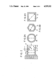
- FIG. 1 is a side view elevation partly in cross-section and partly schematic of the apparatus of the present invention
- FIG. 2 is an enlargement of the cathode assembly of FIG. 1 after operating for an extended period of time with the cathode shown partially evaporated and with a buildup of evaporated material shown on the inside wall surface of the elongated member;
- FIGS. 2A, 2B, and 2C are respective end views of alternate geometries for the cathode and the elongated member
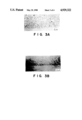
- FIG. 3A is a micrograph showing a cross-sectional view of the microstructure of a TiN coating formed by using prior art physical vapor deposition arc process and apparatus;
- FIG. 3B is a micrograph showing a cross-sectional view of the microstructure of an improved TiN coating formed by arc evaporation in accordance with the physical vapor deposition arc process of the present invention.
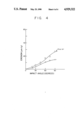
- FIG. 4 is a graph comparing the erosion characteristics of a prior art physical vapor deposition arc evaporated TiN coating versus impact angle against an improved TiN coating formed by the apparatus and method of the present invention.
- FIG. 1 in which the electric arc physical vapor deposition apparatus of the present invention is shown comprising a shell 10 having a vacuum chamber 11 which is evacuated to a desired operating pressure of generally between 10 -1 to 5 ⁇ 10 -4 torr and preferably between 5 ⁇ 10 -2 and 5 ⁇ 10 -3 torr by a conventional vacuum pumping system 12 communicating with the vacuum chamber 11 through an open port 13.
- the vacuum chamber 11 may have any desired geometry and be of any desired size to accommodate one or more objects 14 (substrates) to be coated with source material provided by evaporating one or more solid cathodes 15 in accordance with the practice of the present invention.
- the shell 10 is shown having a generally rectangular body which, in cross-section, has an upper wall 16, a lower wall 17, and side walls 18 and 19, respectively.
- the shell 10 further can include an additional section 20 which projects an arbitrary distance from the side wall 18.
- the side wall 18 has an opening 21 through which the cathode 15 communicates with the vacuum chamber 11.
- the cathode 15 is attached to a cathode support assembly 22.
- the cathode support assembly 22 is mounted on a flange 25 through an insulator 27.
- the mounting flange 25 is connected to section 20 of the shell 10.
- the support block 22 has a relatively small cavity 28 which connects with an inlet passage 29 and exit passages 30.
- a coolant such as water is circulated through the cavity 28 from a source (not shown). The coolant flows from the source through inlet conduit 29 into the cavity 28 and returns to the source through the exit passages 30.
- a DC magnet 33 is disposed within the support block 22 and serves to diffuse the point of attachment of an electric arc 34 over the arc evaporation surface 35 of the cathode 15.
- a hollow elongated member 36 surrounds the cathode 15 to form a relatively narrow space 40.
- the elongated member 36 is attached to the mounting flange 25 through the insulator 27.
- the geometry of the member 36 and open end 41 should substantially conform to the geometry and dimension of the cathode 15 as shown in FIGS. 2A, 2B and 2C, respectively
- the elongated member 36 should be substantially uniform in cross-sectional dimension over its length. This assures that the open end 41 does not restrict the plasma flow as it exits member 36. Accordingly, if a cylindrical or disk shaped cathode is used, the member 36 should preferably be tubular in shape with the narrow space 40 being annular in cross-section.
- the thickness of the annular space 40 can range from about 0.08 cm to about 0.24 cm.
- An inlet opening 38 in the support block 22 directly communicates with the narrow space 40 and with an input gas supply line 39. Gas is fed through the gas supply line 39 from a source of gas (not shown) into the narrow space 40 from whence the gas is directed through the cathode chamber 37 into the vacuum chamber 11.
- a valve V is used to control the flow of gas through the supply line 39.
- the elongated member 36 projects a predetermined distance "x" beyond the cathode evaporable end surface 35 to form a cathode chamber 37.
- the extension "x" between the open end 41 of the member 36 and the evaporable end surface 35 must be above zero and up to a maximum of, for example, about 13 cm in length for a 6.35 cm diameter cathode.
- the distance "x” is measured from the cathode evaporable end surface 35 as shown in FIG. 2 to the open end 41 of the elongated member 36.
- the preferred minimum distance "x" is at least about one centimeter and the preferred range for "x" is between 2 to 6 cm for a 6.35 cm diameter cathode.
- the elongated member 36 may preferably be composed of any material that does not interfere with the function of magnet 33 in diffusing the attachment of electric arc 34 over the arc evaporation surface 35 and can comprise any non-magnetic material suitable for high temperature vacuum service, e.g., non-magnetic stainless steel.
- the object 14 is mounted upon a support plate 42 located within the vacuum chamber 11 and spaced apart from the evaporable end surface 35 of the cathode 15.
- the type of structure used to support or suspend the object 14 within the vacuum chamber 11 depends upon the size, configuration and weight of the object.
- the object 14 is shown having a rectangular geometry with a flat surface facing the cathode evaporation end surface 35. It should be understood that the object 14 may have any configuration and may be supported in any fashion.
- the object 14 may also be of any suitable composition capable of withstanding the high temperature, vacuum conditions existing in the chamber 11 and can be made of such materials as refractory metal, refractory alloy, superalloy, stainless steel, and ceramic composites.
- the support plate 42 should, however, be composed of a conductive material and is connected to a metal rod 42 which extends through an insulated high voltage feed-through port 43 in the lower wall 17 of the shell 10.
- the metal rod 42 is connected to the negative terminal of a bias power supply 44 located external of the shell 10 with the positive terminal of the bias power supply 44 connected to side wall 18 through electrical lead 31.
- the vacuum chamber 11 further can include an electrically insulated surface 70 located opposite the cathode evaporable end surface 35 with the object 14 and support plate 42 positioned therebetween.
- the electrically insulated surface 70 can be itself comprised of an insulator material or can be comprised of a conductive material which is insulated from the chamber 10 by insulator 71 shown. This electrically insulated surface 70 serves to substantially confine the plasma to the chamber volume 72 between surface 70 and cathode evaporable end surface 35 wherein the object 14 is located without surface 70 attracting ions or electrons from the plasma and further serves to prevent interaction between plasmas when multiple evaporators are accommodated in chamber 11.
- Arc current is supplied from a main power supply 46 located external of the shell 10.
- the main power supply 46 has its negative terminal connected to the cathode support block 22 and its positive terminal connected to the side wall 18.
- the electric arc 34 is formed between the cathode 15 and the side wall 18 of the shell 10.
- the side wall 18 represents the anode and can be connected to ground potential 45 through an electrical lead 49.
- the anode may be formed from another conductive member (not shown) mounted adjacent to but electrically separated from the side wall. The geometry of such anode would not be critical.
- the arc conduit can be electrically isolated from the shell 10.
- the side wall 18 can be electrically insulated from the other walls of the shell 10 by using insulating separators such as those shown at 23.
- the anode side wall 18 can be free-floating with the ground at 45 removed and the shell wall 16, 17 and 19 grounded.
- Any conventional arc starting procedure may be used including physically contacting the cathode end surface 35 with a wire electrode 50.
- the wire electrode 50 is electrically connected to anode side wall 18 or a separate anode (not shown) through a high resistance R.
- the wire electrode 50 is connected to a plunger assembly 53 through an insulated sleeve 51 in the mounting flange 25.
- the plunger assembly 53 moves the wire electrode into physical contact with the cathode end surface 35 and then retracts it.
- a conventional plunger assembly for performing this operation is taught and described in U.S. Pat. No. 4,448,799.
- any mechanism capable of moving the starting wire electrode 50 into contact with the cathode 15 and withdrawing it may be used to practice the present invention.
- an arc may be started by other conventional methods including transferred arc starting and spark starting using a spark plug.
- any gas may be supplied to the cathode chamber 37 and then to vacuum chamber 11 through the narrow space 40 of elongated member 36 depending upon the coating to be formed on the object 14.
- an inert gas such as argon is preferred for depositing a coating of elemental or alloy source material corresponding to the cathode material, e.g., Si, Cu, Al, W, Mo, Cr, Ta, Nb, V, Hf, Zr, Ti, Ni, Co, Fe and their alloys including alloying elements Mn, Si, P, Zn, B and C.
- the inert gas in this instance is not intended to react with the metal vapor in the plasma.
- Other inert gases that may be used include neon, krypton, xenon and helium.
- Reactive gases include nitrogen, oxygen, hydrocarbons such as CH 4 and C 2 H 2 , carbon dioxide, carbon monoxide, diborene (B 2 H 6 ), air, silane (SiH 4 ) and combinations.
- Nitrogen is used as the preferred reactive gas with metal vapor from metal cathodes including Ti, Zr, Hf, V, Nb, Ta, Cr, Mo, W, Si and Al to form refractory nitride coatings TiN, Ti 2 N, ZrN, HfN, VN, V 3 N, Nb 2 N, NbN, TaN, Ta 2 N, CrN, Cr 2 N, MoN, Mo 2 N, Mo 3 N, WN, W 2 N, Si 3 N 4 , AlN and their compounds.
- Nitride-metal composites such as TiN-Ni and ZrN-Ni and complex nitrides such as (Ti,Zr)N, (Ti,Al,V)N and (Ti,V)N can be produced by employing multiple or composite cathodes.
- carbide, oxide and boride compound coatings can be produced when a reactive gas comprised of carbon, oxygen and boron is used, for example TiC, TiO, TiO 2 and TiB 2 .
- interstitial nitride-, carbide-, boride- and oxide-compound coatings can also be made by employing more than one reactive gas species, for example, TiCN, TiON and TiOCN. In all cases, the gas should be fed into the cathode chamber 37 and then into the vacuum chamber 11 at rate compatible with the withdrawal rate of the vacuum pumping system to maintain the desired operating pressure of between 10 -1 to 5 ⁇ 10 -4 torr.
- the plasma produced by the high current density arc includes atoms, molecules, ionized atoms and ionized molecules of the cathode evaporation surface 35 and ionized species of gases.
- Biasing the object 14 negatively with respect to the anode or to both the anode and cathode influences the smoothness, uniformity and surface morphology of the coating.
- the bias power supply should be adjusted to a bias potential to optimize the coating operation. For a TiN, or ZrN, coating a bias potential for power supply 44 of between 50 and 400 volts is acceptable with a bias potential between 100 and 200 volts preferred for TiN and a bias potential between 50 and 250 volts preferred for ZrN.
- Gas is fed through the space 40 into the cathode chamber 37 representing the volume of space between the cathode evaporation surface 35 and the open end 41 of the elongated member 36.
- the gas envelops the high current density arc in the cathode chamber 37 over the distance "x" resulting in an increase of plasma pressure and temperature.
- the plasma extends from the cathode evaporation surface 35 through the relatively high pressure region in the cathode chamber 37 and exits through the open end 41 of the elongated member 36 towards the relatively lower pressure region in the vacuum chamber 11, or chamber volume 72, where the negatively biased substrate 14 is located.
- An additional benefit of feeding gas through the narrow space 40 into cathode chamber 37 is that the gas in space 40 serves as an insulator to prevent arcing from the cathode 15 to the member 36.
- a deposit 60 This is diagrammatically illustrated in FIG. 2.
- the gas injected from narrow space 40 prevents the deposit 60 from accumulating and bridging over to the cathode 15. Instead, as the operation proceeds, a convergent nozzle 62 is formed between the deposit 60 and the outer edge 61 of the cathode 15. The outer edge 61 becomes more pronounced as the evaporable end surface 35 is consumed. The gas flows through this convergent nozzle 62 across the face 35 of cathode 15 and into the plasma contained in cathode chamber 37.
- both the evaporable end surface 35 and the outer edge 61 recede enlarging the distance "x".
- the enlargement in the distance "x" is less than about 0.35 cm during normal operation and is therefore insignificant to the method of the invention.
- the deposit 60 apparently continues to accumulate as the edge 61 recedes so as to maintain the dimension "y" of the convergent nozzle 62 substantially constant by shifting its position in conjunction with the eroded outer edge 61.
- the dimension "y” is maintained substantially constant at a value greater than zero and less than about 0.4 cm over the range of operating parameters. Control over the dimension "y” results from the method of introducing gas into the cathode chamber 37.
- the operation of the convergent nozzle 62 is a self-correcting phenomenon which assures that the gas continues to be directed across the face 35 of the cathode 15 as it flows into the cathode chamber 37 from narrow space 40.
- the gas must always first enter the cathode chamber 37 before the gas enters the vacuum chamber 11, or chamber volume 72.
- FIGS. 3A and 3B show a comparison between the microstructure of a TiN coating formed in accordance with prior art practice and in accordance with the process of the present invention.
- the coating produced by the apparatus and method of the present invention is a sound, dense structure with a smooth surface. It was further observed that adjustment of the distance "x" will vary the physical properties of the coating such as its erosion characteristics.
- the graph of FIG. 4 compares the erosion characteristics of a prior art physical vapor deposition arc evaporated TiN coating with a TiN coating formed in accordance with the present invention.
- the degree of erosion is measured against the impact angle at which the eroding alumina material is directed.
- the TiN coating formed in accordance with the present invention using a recess distance of 5.7 cm for "x" and a 6.35 cm diameter cathode results in a relatively flat low erosion characteristic even at impact angles between sixty to ninety degrees compared to the prior art TiN coating which has a comparatively poor erosion characteristic particularly at high impact angles.
- Examples 1 and 2 further illustrate the invention and are carried out in the apparatus shown in FIG. 1 using the materials and process parameters given in Table I below to produce TiN and ZrN coated substrates, respectively, having the I(111)/I(200) intensity ratios, the interplanar spacing values, d 111 , and 90° volume (50 ⁇ m alumina) erosion rate given below for each of Examples 1 and 2.
- the 90° volume erosion rate test is carried out by impacting angular 50 ⁇ m alumina particles using test apparatus based upon ASTM G 76-83 guidelines.
- the test uses compressed air at 248 KPa to deliver at least a 200 g charge of angular 50 ⁇ m alumina particles through a 5 mm diameter nozzle at a nominal rate of 450 g/min. with a nominal velocity of 60 m/s and a nozzle-to-specimen standoff of 10 cm at an impact angle of 90° to the specimen surface.
- TiN and ZrN coatings have been successfully applied on a number of substrate materials such as refractory metals including Ti, Zr, V, Ta, Mo and W, superalloys including Inconel 718, Inconel 738, Waspaloy and A-286, stainless steels including 17-4PH, AISI 304, AISI 316, AISI 403, AISI 422, AISI 410, and AM355, Ti alloys including Ti-6Al-4V and Ti-6Al-2Sn-4Zr-2Mo and Ti-8Al-1Mo-1V, aluminum alloys including 6061 and 7075, WC-CO Cermet, and Al 2 O 3 ceramics.
- substrate materials such as refractory metals including Ti, Zr, V, Ta, Mo and W, superalloys including Inconel 718, Inconel 738, Waspaloy and A-286, stainless steels including 17-4PH, AISI 304, AISI 316, AISI 403, AISI 422, AISI
Abstract
Description
              TABLE I
______________________________________
              Example    Example
              1          2
______________________________________
Coating Composition
                TiN          ZrN
I(111)/I(200)   175          55
d.sub.(111)     2.455 Å  2.656 Å
90° Volume Erosion
                8.5 × 10.sup.-3
                             5.7 × 10.sup.-3
Rate            mm.sup.3 /g  mm.sup.3 /g
Substrate       410SS        IN718
Cathode Composition
                Ti           Zr
Cathode (cylindrical)
                6.35 cm      6.35 cm
Diameter
Dimension "x"   3.8 cm       2.6 cm
Spatial Standoff
                39 cm        30 cm
Chamber Pressure
                0.018 torr   0.042 torr
N.sub.2 Gas Flow
                340 sccm     215 sccm
Arc Current     125 Adc      139 Adc
Substrate Bias  150 Vdc      250 Vdc
Deposition Rate 0.065 μm/min.
                             0.092 μm/min.
Substrate Temp. 480° C.
                             670° C.
______________________________________
Claims (23)
Priority Applications (1)
| Application Number | Priority Date | Filing Date | Title |
|---|---|---|---|
| US07/363,332 US4929322A (en) | 1985-09-30 | 1989-06-08 | Apparatus and process for arc vapor depositing a coating in an evacuated chamber |
Applications Claiming Priority (3)
| Application Number | Priority Date | Filing Date | Title |
|---|---|---|---|
| US78146085A | 1985-09-30 | 1985-09-30 | |
| US90651486A | 1986-09-12 | 1986-09-12 | |
| US07/363,332 US4929322A (en) | 1985-09-30 | 1989-06-08 | Apparatus and process for arc vapor depositing a coating in an evacuated chamber |
Related Parent Applications (1)
| Application Number | Title | Priority Date | Filing Date |
|---|---|---|---|
| US90651486A Continuation | 1985-09-30 | 1986-09-12 |
Publications (1)
| Publication Number | Publication Date |
|---|---|
| US4929322A true US4929322A (en) | 1990-05-29 |
Family
ID=27408609
Family Applications (1)
| Application Number | Title | Priority Date | Filing Date |
|---|---|---|---|
| US07/363,332 Expired - Lifetime US4929322A (en) | 1985-09-30 | 1989-06-08 | Apparatus and process for arc vapor depositing a coating in an evacuated chamber |
Country Status (1)
| Country | Link |
|---|---|
| US (1) | US4929322A (en) |
Cited By (31)
| Publication number | Priority date | Publication date | Assignee | Title |
|---|---|---|---|---|
| US5045344A (en) * | 1989-11-16 | 1991-09-03 | Vapor Technologies, Inc. | Method of making reflective articles |
| US5055421A (en) * | 1987-08-03 | 1991-10-08 | Siemens Aktiengesellschaft | Method for the plasma deposition of hydrogenated, amorphous carbon using predetermined retention times of gaseous hydrocarbons |
| WO1993001327A1 (en) * | 1991-07-11 | 1993-01-21 | The Regents Of The University Of California | Continuous vacuum arc broad beam ion source |
| US5215640A (en) * | 1987-02-03 | 1993-06-01 | Balzers Ag | Method and arrangement for stabilizing an arc between an anode and a cathode particularly for vacuum coating devices |
| US5269896A (en) * | 1991-05-29 | 1993-12-14 | Kabushiki Kaisha Kobe Seiko Sho | Cathodic arc deposition system |
| US5441235A (en) * | 1994-05-20 | 1995-08-15 | Eaton Corporation | Titanium nitride coated valve and method for making |
| US5458754A (en) | 1991-04-22 | 1995-10-17 | Multi-Arc Scientific Coatings | Plasma enhancement apparatus and method for physical vapor deposition |
| EP0725424A1 (en) * | 1995-01-23 | 1996-08-07 | Nissin Electric Company, Limited | Arc-type evaporator |
| US5580429A (en) * | 1992-08-25 | 1996-12-03 | Northeastern University | Method for the deposition and modification of thin films using a combination of vacuum arcs and plasma immersion ion implantation |
| US5895559A (en) * | 1996-04-08 | 1999-04-20 | Christy; Ronald | Cathodic arc cathode |
| WO1999041425A1 (en) * | 1998-02-14 | 1999-08-19 | Phygen, Inc. | Cathode arc vapor deposition |
| US5952061A (en) * | 1996-12-27 | 1999-09-14 | Stanley Electric Co., Ltd. | Fabrication and method of producing silicon films |
| US6207029B1 (en) * | 1995-07-11 | 2001-03-27 | Erich Bergmann | Apparatus for vapor deposition and evaporator |
| WO2001050559A1 (en) * | 2000-01-05 | 2001-07-12 | Honeywell International Inc. | Spark plug having a protective titanium coating thereon, and methods of making same |
| US6365016B1 (en) * | 1999-03-17 | 2002-04-02 | General Electric Company | Method and apparatus for arc plasma deposition with evaporation of reagents |
| US6413358B2 (en) * | 1993-04-16 | 2002-07-02 | Micron Technology, Inc. | Method and apparatus for improving etch uniformity in remote source plasma reactors with powered wafer chucks |
| US6426125B1 (en) * | 1999-03-17 | 2002-07-30 | General Electric Company | Multilayer article and method of making by ARC plasma deposition |
| US6592726B1 (en) * | 1999-03-23 | 2003-07-15 | Sumitomo Electric Industries, Ltd. | Vacuum arc evaporation method, vacuum arc evaporation system, and rotary cutting tool |
| US6602390B1 (en) * | 1994-06-24 | 2003-08-05 | Unaxis Balzers Aktiengesellschaft | Coating a workpiece and operating a cathodic arc discharge |
| US20040172827A1 (en) * | 2003-03-03 | 2004-09-09 | Kinstler Monika D. | Fan and compressor blade dovetail restoration process |
| US20050034668A1 (en) * | 2001-03-22 | 2005-02-17 | Garvey James F. | Multi-component substances and apparatus for preparation thereof |
| CN100336165C (en) * | 2002-11-15 | 2007-09-05 | 三星电子株式会社 | Gas injection apparatus for semiconductor processing system |
| US20070209927A1 (en) * | 2004-07-09 | 2007-09-13 | Masayuki Kamei | Magnetron Sputtering Device In which Two Modes Of Magnetic Flux Distribution (Balanced Mode/Unbalanced Mode) Can Be Switched From One To The Other And Vice Versa, A Film Formation Method For Forming A Film From An Inorganic Film Formation Material Using The Device, And A Dual Mode Magnetron Sputtering Device And Film Formation Method For Forming A Film From An Inorganic Film Formation Material At A Low Temperature Using The Device |
| US20080014371A1 (en) * | 2003-06-13 | 2008-01-17 | Mike Mattlage | Method of Producing a Coated Fishing Hook |
| US20080020138A1 (en) * | 2006-07-19 | 2008-01-24 | Oc Oerlikon Balzers Ag. | Method for manufacturing poorly conductive layers |
| US20090130789A1 (en) * | 2004-12-06 | 2009-05-21 | Samsung Electronics Co., Ltd. | Signal line for display device and thin film transistor array panel including the signal line |
| US20090258165A1 (en) * | 2008-04-14 | 2009-10-15 | United Technologies Corporation | Platinum-modified cathodic arc coating |
| US20100041895A1 (en) * | 2008-06-20 | 2010-02-18 | University Of Georgia Research Foundation, Inc. | Synthesis and Stabilization of Neutral Compounds with Homonuclear Bonds |
| US20120018296A1 (en) * | 2010-07-23 | 2012-01-26 | Hon Hai Precision Industry Co., Ltd. | Continuous vacuum sputtering method |
| US20150001064A1 (en) * | 2011-12-22 | 2015-01-01 | Oerlikon Trading Ag, Trubbach | Low temperature arc ion plating coating |
| US20170369984A1 (en) * | 2016-06-24 | 2017-12-28 | Veeco Instruments Inc. | Enhanced cathodic arc source for arc plasma deposition |
Citations (26)
| Publication number | Priority date | Publication date | Assignee | Title |
|---|---|---|---|---|
| US3625848A (en) * | 1968-12-26 | 1971-12-07 | Alvin A Snaper | Arc deposition process and apparatus |
| US3699623A (en) * | 1970-10-20 | 1972-10-24 | United Aircraft Corp | Method for fabricating corrosion resistant composites |
| US3748110A (en) * | 1971-10-27 | 1973-07-24 | Gen Motors Corp | Ductile corrosion resistant coating for nickel base alloy articles |
| US3772174A (en) * | 1971-04-21 | 1973-11-13 | Nasa | Deposition of alloy films |
| US3783231A (en) * | 1972-03-22 | 1974-01-01 | V Gorbunov | Apparatus for vacuum-evaporation of metals under the action of an electric arc |
| US3793179A (en) * | 1971-07-19 | 1974-02-19 | L Sablev | Apparatus for metal evaporation coating |
| US3801353A (en) * | 1970-06-03 | 1974-04-02 | Chromalloy American Corp | Method for coating heat resistant alloys |
| US3836451A (en) * | 1968-12-26 | 1974-09-17 | A Snaper | Arc deposition apparatus |
| US3922214A (en) * | 1973-03-27 | 1975-11-25 | Cit Alcatel | Device for manufacturing thin layers of mineral substances |
| US3961103A (en) * | 1972-07-12 | 1976-06-01 | Space Sciences, Inc. | Film deposition |
| US4123595A (en) * | 1977-09-22 | 1978-10-31 | General Electric Company | Metallic coated article |
| US4132624A (en) * | 1971-02-05 | 1979-01-02 | Triplex Safety Glass Company Limited | Apparatus for producing metal oxide films |
| JPS5514137A (en) * | 1978-07-14 | 1980-01-31 | Nisshin Oil Mills Ltd:The | Sealing method for gas substitution in can production and apparatus thereof |
| US4197175A (en) * | 1977-06-01 | 1980-04-08 | Balzers Aktiengesellschaft | Method and apparatus for evaporating materials in a vacuum coating plant |
| US4277222A (en) * | 1979-01-11 | 1981-07-07 | Teledyne Industries, Inc. | Turbine engine compressor |
| US4288306A (en) * | 1978-07-08 | 1981-09-08 | Wolfgang Kieferle | Process for forming a metal or alloy layer and device for executing same |
| US4318672A (en) * | 1978-11-06 | 1982-03-09 | Nordisk Ventilator Co. A/S | Particle erosion resistant covering for fan blade leading edge |
| US4418124A (en) * | 1980-10-06 | 1983-11-29 | General Electric Company | Plasma spray-cast components |
| US4448799A (en) * | 1983-04-21 | 1984-05-15 | Multi-Arc Vacuum Systems Inc. | Arc-initiating trigger apparatus and method for electric arc vapor deposition coating systems |
| JPS59182962A (en) * | 1983-04-04 | 1984-10-17 | Toyo Soda Mfg Co Ltd | Apparatus proof against alkali hydroxide solution |
| US4492522A (en) * | 1981-12-24 | 1985-01-08 | Mtu Motoren-Und Turbinen-Union Muenchen Gmbh | Blade for a fluid flow engine and method for manufacturing the blade |
| US4505947A (en) * | 1982-07-14 | 1985-03-19 | The Standard Oil Company (Ohio) | Method for the deposition of coatings upon substrates utilizing a high pressure, non-local thermal equilibrium arc plasma |
| US4512867A (en) * | 1981-11-24 | 1985-04-23 | Andreev Anatoly A | Method and apparatus for controlling plasma generation in vapor deposition |
| US4525415A (en) * | 1981-09-11 | 1985-06-25 | Iscar Limited | Sintered hard metal products having a multi-layer wear-resistant coating |
| US4565747A (en) * | 1983-11-11 | 1986-01-21 | Research Development Corporation | Boron nitride containing titanium nitride, method of producing the same and composite ceramics produced therefrom |
| US4590090A (en) * | 1982-07-28 | 1986-05-20 | General Electric Company | Method for making interdiffused, substantially spherical ceramic powders |
-
1989
- 1989-06-08 US US07/363,332 patent/US4929322A/en not_active Expired - Lifetime
Patent Citations (26)
| Publication number | Priority date | Publication date | Assignee | Title |
|---|---|---|---|---|
| US3625848A (en) * | 1968-12-26 | 1971-12-07 | Alvin A Snaper | Arc deposition process and apparatus |
| US3836451A (en) * | 1968-12-26 | 1974-09-17 | A Snaper | Arc deposition apparatus |
| US3801353A (en) * | 1970-06-03 | 1974-04-02 | Chromalloy American Corp | Method for coating heat resistant alloys |
| US3699623A (en) * | 1970-10-20 | 1972-10-24 | United Aircraft Corp | Method for fabricating corrosion resistant composites |
| US4132624A (en) * | 1971-02-05 | 1979-01-02 | Triplex Safety Glass Company Limited | Apparatus for producing metal oxide films |
| US3772174A (en) * | 1971-04-21 | 1973-11-13 | Nasa | Deposition of alloy films |
| US3793179A (en) * | 1971-07-19 | 1974-02-19 | L Sablev | Apparatus for metal evaporation coating |
| US3748110A (en) * | 1971-10-27 | 1973-07-24 | Gen Motors Corp | Ductile corrosion resistant coating for nickel base alloy articles |
| US3783231A (en) * | 1972-03-22 | 1974-01-01 | V Gorbunov | Apparatus for vacuum-evaporation of metals under the action of an electric arc |
| US3961103A (en) * | 1972-07-12 | 1976-06-01 | Space Sciences, Inc. | Film deposition |
| US3922214A (en) * | 1973-03-27 | 1975-11-25 | Cit Alcatel | Device for manufacturing thin layers of mineral substances |
| US4197175A (en) * | 1977-06-01 | 1980-04-08 | Balzers Aktiengesellschaft | Method and apparatus for evaporating materials in a vacuum coating plant |
| US4123595A (en) * | 1977-09-22 | 1978-10-31 | General Electric Company | Metallic coated article |
| US4288306A (en) * | 1978-07-08 | 1981-09-08 | Wolfgang Kieferle | Process for forming a metal or alloy layer and device for executing same |
| JPS5514137A (en) * | 1978-07-14 | 1980-01-31 | Nisshin Oil Mills Ltd:The | Sealing method for gas substitution in can production and apparatus thereof |
| US4318672A (en) * | 1978-11-06 | 1982-03-09 | Nordisk Ventilator Co. A/S | Particle erosion resistant covering for fan blade leading edge |
| US4277222A (en) * | 1979-01-11 | 1981-07-07 | Teledyne Industries, Inc. | Turbine engine compressor |
| US4418124A (en) * | 1980-10-06 | 1983-11-29 | General Electric Company | Plasma spray-cast components |
| US4525415A (en) * | 1981-09-11 | 1985-06-25 | Iscar Limited | Sintered hard metal products having a multi-layer wear-resistant coating |
| US4512867A (en) * | 1981-11-24 | 1985-04-23 | Andreev Anatoly A | Method and apparatus for controlling plasma generation in vapor deposition |
| US4492522A (en) * | 1981-12-24 | 1985-01-08 | Mtu Motoren-Und Turbinen-Union Muenchen Gmbh | Blade for a fluid flow engine and method for manufacturing the blade |
| US4505947A (en) * | 1982-07-14 | 1985-03-19 | The Standard Oil Company (Ohio) | Method for the deposition of coatings upon substrates utilizing a high pressure, non-local thermal equilibrium arc plasma |
| US4590090A (en) * | 1982-07-28 | 1986-05-20 | General Electric Company | Method for making interdiffused, substantially spherical ceramic powders |
| JPS59182962A (en) * | 1983-04-04 | 1984-10-17 | Toyo Soda Mfg Co Ltd | Apparatus proof against alkali hydroxide solution |
| US4448799A (en) * | 1983-04-21 | 1984-05-15 | Multi-Arc Vacuum Systems Inc. | Arc-initiating trigger apparatus and method for electric arc vapor deposition coating systems |
| US4565747A (en) * | 1983-11-11 | 1986-01-21 | Research Development Corporation | Boron nitride containing titanium nitride, method of producing the same and composite ceramics produced therefrom |
Non-Patent Citations (12)
| Title |
|---|
| H. J. Kolkman, "Erosion of Corrosion Resistant Coatings for Jet Engine Compressors", Proc. 6th Int. Conf. on Erosion by Liquid and Solid Impact. |
| H. J. Kolkman, Erosion of Corrosion Resistant Coatings for Jet Engine Compressors , Proc. 6th Int. Conf. on Erosion by Liquid and Solid Impact. * |
| K. Salmenoja et al, "The Use of Optical Emission Spectroscopy for Process Control in Triode Ion Plating with ZrN" Vacuum, vol. 36, Nos. 1-3, 33-35, 1986. |
| K. Salmenoja et al, The Use of Optical Emission Spectroscopy for Process Control in Triode Ion Plating with ZrN Vacuum, vol. 36, Nos. 1 3, 33 35, 1986. * |
| R. G. Duckworth et al, Paper in Thin Solid Films, 63 (1979), 289 297. * |
| R. G. Duckworth et al, Paper in Thin Solid Films, 63 (1979), 289-297. |
| W. D. Sproul et al, "Reactively Sputtered TiN, ZrN, and HfN", Invited Paper, Extended Abstract, 1984 AVS National Symposium, Reno, Nev. |
| W. D. Sproul et al, Reactively Sputtered TiN, ZrN, and HfN , Invited Paper, Extended Abstract, 1984 AVS National Symposium, Reno, Nev. * |
| William D. Sproul, "Hafnium Nitride Coatings Prepared by Very High Rate Reactive Sputtering", Thin Solid Films, 118 (1984), 279-284. |
| William D. Sproul, "Very High Rate Reactive Sputtering on TiN, ZrN, and HfN" Thin Solid Films, 107 (1983), 141-147. |
| William D. Sproul, Hafnium Nitride Coatings Prepared by Very High Rate Reactive Sputtering , Thin Solid Films, 118 (1984), 279 284. * |
| William D. Sproul, Very High Rate Reactive Sputtering on TiN, ZrN, and HfN Thin Solid Films, 107 (1983), 141 147. * |
Cited By (53)
| Publication number | Priority date | Publication date | Assignee | Title |
|---|---|---|---|---|
| US5387326A (en) * | 1987-02-03 | 1995-02-07 | Balzers Ag | Method and arrangement for stabilizing an arc between an anode and a cathode particularly for vacuum coating devices |
| US5215640A (en) * | 1987-02-03 | 1993-06-01 | Balzers Ag | Method and arrangement for stabilizing an arc between an anode and a cathode particularly for vacuum coating devices |
| US5055421A (en) * | 1987-08-03 | 1991-10-08 | Siemens Aktiengesellschaft | Method for the plasma deposition of hydrogenated, amorphous carbon using predetermined retention times of gaseous hydrocarbons |
| US5045344A (en) * | 1989-11-16 | 1991-09-03 | Vapor Technologies, Inc. | Method of making reflective articles |
| US6139964A (en) | 1991-04-22 | 2000-10-31 | Multi-Arc Inc. | Plasma enhancement apparatus and method for physical vapor deposition |
| US5458754A (en) | 1991-04-22 | 1995-10-17 | Multi-Arc Scientific Coatings | Plasma enhancement apparatus and method for physical vapor deposition |
| US5269896A (en) * | 1991-05-29 | 1993-12-14 | Kabushiki Kaisha Kobe Seiko Sho | Cathodic arc deposition system |
| WO1993001327A1 (en) * | 1991-07-11 | 1993-01-21 | The Regents Of The University Of California | Continuous vacuum arc broad beam ion source |
| US5580429A (en) * | 1992-08-25 | 1996-12-03 | Northeastern University | Method for the deposition and modification of thin films using a combination of vacuum arcs and plasma immersion ion implantation |
| US20050173376A1 (en) * | 1993-04-16 | 2005-08-11 | Donohoe Kevin G. | Method for etching a wafer in a plasma etch reactor |
| US6946053B2 (en) * | 1993-04-16 | 2005-09-20 | Micron Technology, Inc. | Plasma reactor |
| US6500300B2 (en) | 1993-04-16 | 2002-12-31 | Micron Technology, Inc. | Plasma reactor |
| US6413358B2 (en) * | 1993-04-16 | 2002-07-02 | Micron Technology, Inc. | Method and apparatus for improving etch uniformity in remote source plasma reactors with powered wafer chucks |
| US20030062127A1 (en) * | 1993-04-16 | 2003-04-03 | Micron Technology, Inc. | Plasma reactor |
| US5441235A (en) * | 1994-05-20 | 1995-08-15 | Eaton Corporation | Titanium nitride coated valve and method for making |
| US6702931B2 (en) * | 1994-06-24 | 2004-03-09 | Unaxis Balzers Ag | Method for manufacturing a cathodic arc coated workpiece |
| US6602390B1 (en) * | 1994-06-24 | 2003-08-05 | Unaxis Balzers Aktiengesellschaft | Coating a workpiece and operating a cathodic arc discharge |
| US5843293A (en) * | 1995-01-23 | 1998-12-01 | Nissin Electric Co., Ltd. | Arc-type evaporator |
| EP0725424A1 (en) * | 1995-01-23 | 1996-08-07 | Nissin Electric Company, Limited | Arc-type evaporator |
| US6207029B1 (en) * | 1995-07-11 | 2001-03-27 | Erich Bergmann | Apparatus for vapor deposition and evaporator |
| US5895559A (en) * | 1996-04-08 | 1999-04-20 | Christy; Ronald | Cathodic arc cathode |
| US5952061A (en) * | 1996-12-27 | 1999-09-14 | Stanley Electric Co., Ltd. | Fabrication and method of producing silicon films |
| WO1999041425A1 (en) * | 1998-02-14 | 1999-08-19 | Phygen, Inc. | Cathode arc vapor deposition |
| US6103074A (en) * | 1998-02-14 | 2000-08-15 | Phygen, Inc. | Cathode arc vapor deposition method and apparatus |
| US6426125B1 (en) * | 1999-03-17 | 2002-07-30 | General Electric Company | Multilayer article and method of making by ARC plasma deposition |
| US6365016B1 (en) * | 1999-03-17 | 2002-04-02 | General Electric Company | Method and apparatus for arc plasma deposition with evaporation of reagents |
| US6592726B1 (en) * | 1999-03-23 | 2003-07-15 | Sumitomo Electric Industries, Ltd. | Vacuum arc evaporation method, vacuum arc evaporation system, and rotary cutting tool |
| WO2001050559A1 (en) * | 2000-01-05 | 2001-07-12 | Honeywell International Inc. | Spark plug having a protective titanium coating thereon, and methods of making same |
| US6452314B1 (en) | 2000-01-05 | 2002-09-17 | Honeywell International Inc. | Spark plug having a protective titanium thereon, and methods of making the same |
| US20050034668A1 (en) * | 2001-03-22 | 2005-02-17 | Garvey James F. | Multi-component substances and apparatus for preparation thereof |
| CN100336165C (en) * | 2002-11-15 | 2007-09-05 | 三星电子株式会社 | Gas injection apparatus for semiconductor processing system |
| US20040172827A1 (en) * | 2003-03-03 | 2004-09-09 | Kinstler Monika D. | Fan and compressor blade dovetail restoration process |
| US8122600B2 (en) * | 2003-03-03 | 2012-02-28 | United Technologies Corporation | Fan and compressor blade dovetail restoration process |
| US20080014371A1 (en) * | 2003-06-13 | 2008-01-17 | Mike Mattlage | Method of Producing a Coated Fishing Hook |
| US20070209927A1 (en) * | 2004-07-09 | 2007-09-13 | Masayuki Kamei | Magnetron Sputtering Device In which Two Modes Of Magnetic Flux Distribution (Balanced Mode/Unbalanced Mode) Can Be Switched From One To The Other And Vice Versa, A Film Formation Method For Forming A Film From An Inorganic Film Formation Material Using The Device, And A Dual Mode Magnetron Sputtering Device And Film Formation Method For Forming A Film From An Inorganic Film Formation Material At A Low Temperature Using The Device |
| WO2006085994A2 (en) * | 2004-08-09 | 2006-08-17 | Biomed Solutions, Llc | Multi-component substances and apparatus for preparation thereof |
| WO2006085994A3 (en) * | 2004-08-09 | 2007-03-29 | Biomed Solutions Llc | Multi-component substances and apparatus for preparation thereof |
| US20090130789A1 (en) * | 2004-12-06 | 2009-05-21 | Samsung Electronics Co., Ltd. | Signal line for display device and thin film transistor array panel including the signal line |
| US7662676B2 (en) * | 2004-12-06 | 2010-02-16 | Samsung Electronics Co., Ltd. | Signal line for display device and thin film transistor array panel including the signal line |
| US7857948B2 (en) * | 2006-07-19 | 2010-12-28 | Oerlikon Trading Ag, Trubbach | Method for manufacturing poorly conductive layers |
| US20080020138A1 (en) * | 2006-07-19 | 2008-01-24 | Oc Oerlikon Balzers Ag. | Method for manufacturing poorly conductive layers |
| US8968528B2 (en) * | 2008-04-14 | 2015-03-03 | United Technologies Corporation | Platinum-modified cathodic arc coating |
| US20090258165A1 (en) * | 2008-04-14 | 2009-10-15 | United Technologies Corporation | Platinum-modified cathodic arc coating |
| US20100041895A1 (en) * | 2008-06-20 | 2010-02-18 | University Of Georgia Research Foundation, Inc. | Synthesis and Stabilization of Neutral Compounds with Homonuclear Bonds |
| US8278456B2 (en) | 2008-06-20 | 2012-10-02 | University Of Georgia Research Foundation, Inc. | Synthesis and stabilization of neutral compounds with homonuclear bonds |
| US20120018296A1 (en) * | 2010-07-23 | 2012-01-26 | Hon Hai Precision Industry Co., Ltd. | Continuous vacuum sputtering method |
| US8623182B2 (en) * | 2010-07-23 | 2014-01-07 | Hon Hai Precision Industry Co., Ltd. | Continuous vacuum deposition method |
| US20150001064A1 (en) * | 2011-12-22 | 2015-01-01 | Oerlikon Trading Ag, Trubbach | Low temperature arc ion plating coating |
| US10865472B2 (en) * | 2011-12-22 | 2020-12-15 | Oerlikon Surface Solutions Ag, Pfäffikon | Low temperature arc ion plating coating |
| US20170369984A1 (en) * | 2016-06-24 | 2017-12-28 | Veeco Instruments Inc. | Enhanced cathodic arc source for arc plasma deposition |
| CN107541705A (en) * | 2016-06-24 | 2018-01-05 | 威科仪器有限公司 | For the enhanced cathode arc source of arc plasma deposition |
| CN107541705B (en) * | 2016-06-24 | 2020-12-04 | 威科仪器有限公司 | Enhanced cathode arc source for arc plasma deposition |
| US11466360B2 (en) | 2016-06-24 | 2022-10-11 | Veeco Instruments Inc. | Enhanced cathodic ARC source for ARC plasma deposition |
Similar Documents
| Publication | Publication Date | Title |
|---|---|---|
| US4929322A (en) | Apparatus and process for arc vapor depositing a coating in an evacuated chamber | |
| US4895765A (en) | Titanium nitride and zirconium nitride coating compositions, coated articles and methods of manufacture | |
| US4749587A (en) | Process for depositing layers on substrates in a vacuum chamber | |
| US4419202A (en) | Metal coatings | |
| EP0238643B1 (en) | Apparatus and process for arc vapor depositing a coating in an evacuated chamber | |
| JP5306198B2 (en) | Electrical insulation film deposition method | |
| JPS63230866A (en) | Vacuum vapor deposition method and apparatus by arc discharge between anode and cathode | |
| MX2011005039A (en) | Method for pretreating substrates for pvd methods. | |
| US6110540A (en) | Plasma apparatus and method | |
| KR101696838B1 (en) | Sputtering apparatus for forming nano-structure | |
| JP3198658B2 (en) | Sputtering equipment | |
| JPH0236674B2 (en) | ||
| US20040261311A1 (en) | Fishing hook | |
| US20080014371A1 (en) | Method of Producing a Coated Fishing Hook | |
| CA2201810A1 (en) | Gas-controlled arc apparatus and process | |
| JPH06220621A (en) | Device for forming film by sputtering | |
| WO2022261684A1 (en) | Apparatus and method for coating the inner surface of a hollow article | |
| KR950000010B1 (en) | Ion plating method and processing apparatus therefor | |
| JPH0428862A (en) | Plasma producing device | |
| Charrier et al. | Carbon films deposited by the physical vapour deposition focused-arc evaporation technique | |
| JP4868534B2 (en) | Method for depositing a high melting point metal carbide layer | |
| JP2001011600A (en) | Device and method for film formation | |
| JPH1068070A (en) | Formation of compound coating | |
| JPH0477074B2 (en) | ||
| JP2001262338A (en) | Sputter film deposition system |
Legal Events
| Date | Code | Title | Description |
|---|---|---|---|
| FEPP | Fee payment procedure |
Free format text: PAYOR NUMBER ASSIGNED (ORIGINAL EVENT CODE: ASPN); ENTITY STATUS OF PATENT OWNER: LARGE ENTITY |
|
| STCF | Information on status: patent grant |
Free format text: PATENTED CASE |
|
| AS | Assignment |
Owner name: UNION CARBIDE COATINGS SERVICE TECHNOLOGY CORPORAT Free format text: ASSIGNMENT OF ASSIGNORS INTEREST.;ASSIGNOR:UNION CARBIDE COATINGS SERVICE CORPORATION, A CORP. OF DELAWARE;REEL/FRAME:005602/0282 Effective date: 19910212 |
|
| CC | Certificate of correction | ||
| AS | Assignment |
Owner name: PRAXAIR S.T. TECHNOLOGY, INC., COLORADO Free format text: CHANGE OF NAME;ASSIGNOR:UNION CARBIDE COATINGS SERVICE TECHNOLOGY CORPORATION;REEL/FRAME:006334/0986 Effective date: 19920611 |
|
| FPAY | Fee payment |
Year of fee payment: 4 |
|
| FEPP | Fee payment procedure |
Free format text: PAYER NUMBER DE-ASSIGNED (ORIGINAL EVENT CODE: RMPN); ENTITY STATUS OF PATENT OWNER: LARGE ENTITY Free format text: PAYOR NUMBER ASSIGNED (ORIGINAL EVENT CODE: ASPN); ENTITY STATUS OF PATENT OWNER: LARGE ENTITY |
|
| FPAY | Fee payment |
Year of fee payment: 8 |
|
| FPAY | Fee payment |
Year of fee payment: 12 |
|
| REMI | Maintenance fee reminder mailed |