US4928539A - Device for automatically taking liquid from a bottle - Google Patents
Device for automatically taking liquid from a bottle Download PDFInfo
- Publication number
- US4928539A US4928539A US07/104,101 US10410187A US4928539A US 4928539 A US4928539 A US 4928539A US 10410187 A US10410187 A US 10410187A US 4928539 A US4928539 A US 4928539A
- Authority
- US
- United States
- Prior art keywords
- sample taking
- needle
- sample
- mobile
- support block
- Prior art date
- Legal status (The legal status is an assumption and is not a legal conclusion. Google has not performed a legal analysis and makes no representation as to the accuracy of the status listed.)
- Expired - Lifetime
Links
Images

Classifications
-
- G—PHYSICS
- G01—MEASURING; TESTING
- G01N—INVESTIGATING OR ANALYSING MATERIALS BY DETERMINING THEIR CHEMICAL OR PHYSICAL PROPERTIES
- G01N35/00—Automatic analysis not limited to methods or materials provided for in any single one of groups G01N1/00 - G01N33/00; Handling materials therefor
- G01N35/10—Devices for transferring samples or any liquids to, in, or from, the analysis apparatus, e.g. suction devices, injection devices
- G01N35/1079—Devices for transferring samples or any liquids to, in, or from, the analysis apparatus, e.g. suction devices, injection devices with means for piercing stoppers or septums
-
- G—PHYSICS
- G01—MEASURING; TESTING
- G01N—INVESTIGATING OR ANALYSING MATERIALS BY DETERMINING THEIR CHEMICAL OR PHYSICAL PROPERTIES
- G01N35/00—Automatic analysis not limited to methods or materials provided for in any single one of groups G01N1/00 - G01N33/00; Handling materials therefor
- G01N2035/00465—Separating and mixing arrangements
- G01N2035/00524—Mixing by agitating sample carrier
-
- G—PHYSICS
- G01—MEASURING; TESTING
- G01N—INVESTIGATING OR ANALYSING MATERIALS BY DETERMINING THEIR CHEMICAL OR PHYSICAL PROPERTIES
- G01N35/00—Automatic analysis not limited to methods or materials provided for in any single one of groups G01N1/00 - G01N33/00; Handling materials therefor
- G01N35/02—Automatic analysis not limited to methods or materials provided for in any single one of groups G01N1/00 - G01N33/00; Handling materials therefor using a plurality of sample containers moved by a conveyor system past one or more treatment or analysis stations
- G01N35/04—Details of the conveyor system
- G01N2035/0401—Sample carriers, cuvettes or reaction vessels
- G01N2035/0403—Sample carriers with closing or sealing means
-
- G—PHYSICS
- G01—MEASURING; TESTING
- G01N—INVESTIGATING OR ANALYSING MATERIALS BY DETERMINING THEIR CHEMICAL OR PHYSICAL PROPERTIES
- G01N35/00—Automatic analysis not limited to methods or materials provided for in any single one of groups G01N1/00 - G01N33/00; Handling materials therefor
- G01N35/02—Automatic analysis not limited to methods or materials provided for in any single one of groups G01N1/00 - G01N33/00; Handling materials therefor using a plurality of sample containers moved by a conveyor system past one or more treatment or analysis stations
- G01N35/04—Details of the conveyor system
- G01N2035/0439—Rotary sample carriers, i.e. carousels
- G01N2035/0441—Rotary sample carriers, i.e. carousels for samples
-
- G—PHYSICS
- G01—MEASURING; TESTING
- G01N—INVESTIGATING OR ANALYSING MATERIALS BY DETERMINING THEIR CHEMICAL OR PHYSICAL PROPERTIES
- G01N35/00—Automatic analysis not limited to methods or materials provided for in any single one of groups G01N1/00 - G01N33/00; Handling materials therefor
- G01N35/10—Devices for transferring samples or any liquids to, in, or from, the analysis apparatus, e.g. suction devices, injection devices
- G01N35/1004—Cleaning sample transfer devices
Definitions
- the invention relates to a device for automatically taking liquid from a bottle and more precisely a tube plug piercing assembly for taking blood samples.
- the stoppers of the tubes must therefore be pierced automatically and reliably by means of a device which is readily associated with the automatic counting devices for which they form an efficient auxiliary apparatus.
- the piston rod which controls the mobile piece carrying the sample taking needle itself serves as guide for this mobile piece, in association with another guide, and the force exerted is not centered on this mobile piece and is cantilevered, that is to say that the movement of the needle under the action of this offcentered force may be disturbed by the play which said piece may take on, possibly causing jamming thereof.
- the system thus described uses an appreciable number of complicated profile pieces, taking up a not inconsiderable space to the detriment of mounting the assembly and its cost price.
- the invention consequently provides a stopper piercing assembly for automatically taking liquid from a bottle and more particularly blood from a tube, which answers these requirements and which avoids the drawbacks experienced by known systems.
- the invention provides a device for automatically taking liquid from a bottle presented upside down opposite a sample taking needle intended to pierce the stopper of the bottle and penetrate into the liquid, including a mobile support for storing a plurality of bottles allowing a bottle to be placed in a correct position with respect to a stopper piercing assembly, said assembly including a mobile block serving as support for a sample taking needle, which moves under the action of an actuating cylinder, a rinsing receptacle being fixedly mounted through which the needle passes, in which device said mobile block slides on two fixed guide columns between which the sample taking needle moves vertically under the action of an actuating cylinder with horizontal movement transmission and in which a fixed spacer is mounted bearing on the two columns, at their upper part, and serves as support for the rinsing receptacle.
- At least one bell-crank linkage of substantially triangular shape forms the member for transmitting the movement of the mobile rod of the actuating cylinder to the mobile block and is pivotally mounted on a fixed pin itself mounted on a bracket secured to a support plate carrying the guide columns, each bell crank linkage cooperating with the mobile block through a spur formed by a bearing in an oval recess provided on the side wall of the mobile block.
- the device of the invention has the advantage of requiring reduced space which avoids having to increase the height of the automatic device so as to be able to house it or else of encumbering the rear face of the means holding the samples. Furthermore, the device of the invention is easy to machine and mount, so of a low cost price, and it operates reliably since driving of the mobile element is provided without cantilevering nor with lateral force.
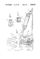
- FIG. 1 a schematical elevational view of the piercing assembly in the rest position
- FIGS. 2 and 3 plane views through II--II and III--III of FIG. 1;
- FIG. 4 a schematical view of the piercing assembly in the sample taking position
- FIG. 5 a sectional view through line V--V of FIG. 1.
- the automatic sample taking device includes essentially a rotary dispenser 1 for sample taking tubes or bottles 2, disposed above a piercing assembly mounted on a base 4.
- a selected tube 2 is automatically positioned as shown in a vertical liquid sample taking position and upside down (i.e., inverted), the stopper 3 being at the low part.
- On a support plate 5 fixed to base 4 are mounted a bracket 9 and two vertical guide columns 6.
- Bracket 9 is provided with a horizontal pin 7 by means of which two bell crank linkages 8 of substantially triangular shapes are mounted on each side of the bracket and each apex of which receives a pivot and/or hinge pin.
- each bell crank linkage 8 form the members for transmitting movement between a drive means formed by an actuating cylinder 12 and a sample taking needle 21 the vertical guide columns 6 being located on opposite sides of a vertical path of travel of the needle. There is thus transmission of a horizontal movement of the cylinder to a vertical movement of the mobile block.
- the upper ends of each bell crank linkage 8 are journalled by a horizontal pin 19 to a bearing 10 screwed on the mobile rod or piston 11 of a pneumatic cylinder 12.
- Said cylinder, fed with fluid through flexible pipes 13, is hingedly mounted to a stirrup 14 itself secured to base 4.
- the lower ends of each bell crank linkage 8 are provided with bearings 15 which cooperate with oval recesses 16 in the opposite side walls of a mobile block 17.
- This mobile block is provided with two vertical openings through which it is fitted on the guide column 6, ball guides 18 being provided on the mobile block for facilitating sliding of the block along the columns.
- a mobile block 17 has centrally a cavity 28 in which is positioned the lower end of a stop 20 for a sample taking needle 21, stop 20 being brazed to the needle 21 and said cavity being extended by a well 32 which opens at the lower part of the mobile block.
- a needle locking sleeve 22 fitted above stop 20 is locked in position by a screw 30 which passes through the mobile block 17.
- the lower end of needle 21 projects from the bottom of cavity 28 into well 32 which passes through the mobile block, and is connected to a flexible pipe 31 which extends under said block and which allows transfer of the fluid sample taken.
- the top part of the guide column 6 is fixed to a fixed spacer 23, secured thereto, which is in the form of a rectangular plate formed with a central orifice 24. Orifice 24 opens onto the upper face of the spacer in the middle of a piece 25 forming a guide for the sample taking needle, which guide is held in position at the upper part of the spacer.
- Spacer 23 is fixed to column 6 by means of point screws 29.
- a rinsing receptacle 26, a lower orifice of which corresponds to orifice 24, is fixed above spacer 23 and is sealingly traversed by the sample taking needle 21.
- Receptacle 26 is provided on the side with a supply and drain pipe 27.
- one of tubes 2 carried by the rotary dispenser is selected by the operator who, for example, sets its reference number on an indexing keyboard.
- the dispenser rotates until the tube is in the position shown in FIG. 1.
- rod 11 of the pneumatic cylinder 12 is extended and the mobile block 17 is at rest bearing on the support plate 5.
- the upper end of needle 21 is at the level of the rinsing receptacle 26.
- the piercing assembly is automatically set in operation as shown in FIG. 4.
- the rod 11 of cylinder 12 retracts and through bearing 10 causes the bell crank linkages 8 to pivot about pin 7.
- the needle 21 fast with the mobile block also rises through orifice 24 and guide 25. It passes through stopper 3 and its end, which is inside the sample tube 2, allows the blood sample to be taken which is pumped by passing through the needle and the flexible pipe 31. Then the piercing assembly comes back to its initial position. The upper end of syringe 21 is rinsed in receptacle 26 which is fed with rinsing fluid through pipe 27.
- the whole of the above described apparatus occupies a reduced space, which avoids increasing the total height of the automatic device or encumbering the rear face of the means holding the samples, and it only requires a few parts which are simple to produce and mount, and therefore inexpensive. All these programmed operations are automatically and rapidly carried out so as to be able to take a succession of samples at a good rate. Venting to the atmosphere is also provided during sample taking for compensating the volume removed and avoiding a depression in the tube.
Abstract
Description
Claims (16)
Applications Claiming Priority (2)
| Application Number | Priority Date | Filing Date | Title |
|---|---|---|---|
| FR8613875 | 1986-10-06 | ||
| FR8613875A FR2604789B1 (en) | 1986-10-06 | 1986-10-06 | DEVICE FOR AUTOMATICALLY TAKING LIQUID FROM A BOTTLE |
Publications (1)
| Publication Number | Publication Date |
|---|---|
| US4928539A true US4928539A (en) | 1990-05-29 |
Family
ID=9339568
Family Applications (1)
| Application Number | Title | Priority Date | Filing Date |
|---|---|---|---|
| US07/104,101 Expired - Lifetime US4928539A (en) | 1986-10-06 | 1987-10-05 | Device for automatically taking liquid from a bottle |
Country Status (6)
| Country | Link |
|---|---|
| US (1) | US4928539A (en) |
| EP (1) | EP0263753B1 (en) |
| JP (1) | JPH0718887B2 (en) |
| DE (1) | DE3767958D1 (en) |
| ES (1) | ES2022913B3 (en) |
| FR (1) | FR2604789B1 (en) |
Cited By (29)
| Publication number | Priority date | Publication date | Assignee | Title |
|---|---|---|---|---|
| US5171530A (en) * | 1990-02-28 | 1992-12-15 | The Perkin-Elmer Corporation | Vial locator and sensor |
| US5262049A (en) * | 1990-11-14 | 1993-11-16 | Biomedical Devices Company | Fluid collecting and dispensing system |
| US5270212A (en) * | 1991-03-20 | 1993-12-14 | Hitachi, Ltd. | Cell analysis apparatus |
| WO1994001745A1 (en) * | 1992-07-09 | 1994-01-20 | Ovonic Battery Company, Inc. | Apparatus for measuring the pressure inside a rechargeable electrochemical cell |
| US5380486A (en) * | 1991-04-19 | 1995-01-10 | Olympus Optical Co., Ltd. | Apparatus for taking liquid content for use in analysis out of container |
| US5426593A (en) * | 1991-02-19 | 1995-06-20 | Seiden; Louis W. | Gas content measurement |
| US5455007A (en) * | 1994-05-27 | 1995-10-03 | Coulter Corporation | Universal stripper plate |
| US5525298A (en) * | 1991-04-19 | 1996-06-11 | Olympus Optical Co., Ltd. | Apparatus for taking liquid content for use in analysis out of container |
| DE19542921A1 (en) * | 1995-03-02 | 1996-09-05 | Bernd Dr Steinbrenner | Magazine, presentation station and refill unit for the provision of objects for laboratory use |
| US5558838A (en) * | 1993-09-29 | 1996-09-24 | Becton Dickinson And Company | Sample preparation apparatus |
| AU675228B2 (en) * | 1992-06-11 | 1997-01-30 | Abx | Device for the transfer, agitaton and sampling of blood products in tubes grouped in cassettes |
| US5665309A (en) * | 1995-02-07 | 1997-09-09 | Abx | Device for agitating and for taking samples of blood products from tubes which are grouped together in racks |
| US5744099A (en) * | 1995-09-15 | 1998-04-28 | Cytek Development Inc. | Apparatus for transfer of biological fluids |
| WO1998021562A1 (en) * | 1996-11-15 | 1998-05-22 | Biochem Immunosystems Inc. | A blood cell analyzer with tube holder and cap piercer |
| US5795784A (en) | 1996-09-19 | 1998-08-18 | Abbott Laboratories | Method of performing a process for determining an item of interest in a sample |
| US5856194A (en) | 1996-09-19 | 1999-01-05 | Abbott Laboratories | Method for determination of item of interest in a sample |
| US5901748A (en) * | 1993-05-19 | 1999-05-11 | Proteus Developments Limited | Selector valve |
| US6126903A (en) * | 1996-11-15 | 2000-10-03 | Biochem Immunosystems, Inc. | Blood cell analyzer with tube holder and cap piercer |
| US6324926B1 (en) * | 1998-09-14 | 2001-12-04 | Innotrac Diagnostisc Oy | Method and device for taking a sample from a closed test tube |
| US6673317B2 (en) * | 1996-06-28 | 2004-01-06 | Kasen Nozzle Mfg. Co., Ltd. | Automatic testing apparatus |
| US6809804B1 (en) | 2000-05-11 | 2004-10-26 | Becton, Dickinson And Company | System and method for providing improved event reading and data processing capabilities in a flow cytometer |
| US20070016160A1 (en) * | 2005-07-07 | 2007-01-18 | Eisai Co., Ltd. | Recovery system |
| US20080156377A1 (en) * | 2006-12-29 | 2008-07-03 | Brad Mann | Recovery system |
| US20100180980A1 (en) * | 2007-08-03 | 2010-07-22 | Enigma Diagnostics Limited | Sample processor |
| US20100291618A1 (en) * | 2009-05-15 | 2010-11-18 | Biomerieux, Inc. | Methods for rapid identification and/or characterization of a microbial agent in a sample |
| US20100291619A1 (en) * | 2009-05-15 | 2010-11-18 | Biomerieux, Inc. | Combined detection instrument for culture specimen containers and instrument for identification and/or characterization of a microbial agent in a sample |
| US20100297707A1 (en) * | 2007-08-03 | 2010-11-25 | Enigma Diagnostics Limited | Reaction vessel comprising conductive layer and inner non-metallic layer |
| US20110212491A1 (en) * | 2007-08-03 | 2011-09-01 | Enigma Diagnostics Limited | Reaction vessel |
| CN111551411A (en) * | 2020-03-11 | 2020-08-18 | 吉林工程技术师范学院 | Acid adding device for geological mineral sample detection |
Families Citing this family (7)
| Publication number | Priority date | Publication date | Assignee | Title |
|---|---|---|---|---|
| US5555920A (en) * | 1991-04-30 | 1996-09-17 | Automed Corporation | Method and apparatus for aliquotting blood serum or blood plasma |
| US5163582A (en) * | 1991-04-30 | 1992-11-17 | Andronic Devices Ltd. | Apparatus and method for aliquotting blood serum or blood plasma |
| US5211310A (en) * | 1991-04-30 | 1993-05-18 | Andronic Devices Ltd. | Apparatus and method for dispensing phases of blood |
| US5322192A (en) * | 1992-07-28 | 1994-06-21 | Automed Corporation | Pipetting apparatus |
| JP4658411B2 (en) * | 2001-09-11 | 2011-03-23 | シスメックス株式会社 | Flow path connection mechanism and reagent holder provided with the same |
| CN102380432B (en) * | 2011-07-19 | 2013-07-10 | 烟台艾德康生物科技有限公司 | Dual-cam synchronous needle distributing mechanism for automatic loading gun |
| CN107188105B (en) * | 2017-06-24 | 2022-09-02 | 潍坊现代科技发展有限公司 | Full-automatic bottle overturning soup pouring machine |
Citations (16)
| Publication number | Priority date | Publication date | Assignee | Title |
|---|---|---|---|---|
| US3266322A (en) * | 1964-06-15 | 1966-08-16 | Technicon Instr | Automatic liquid sample supply and wash apparatus for automatic analysis system |
| US3469438A (en) * | 1967-04-12 | 1969-09-30 | Perkin Elmer Corp | Automatically controlled multiple sampling measurement system |
| US3614434A (en) * | 1968-07-17 | 1971-10-19 | Lofstrom James E | Automatic agitating and sample device |
| FR2136707A5 (en) * | 1971-04-29 | 1972-12-22 | Hoffmann La Roche | |
| US3788177A (en) * | 1971-07-02 | 1974-01-29 | R Williamson | Forming tool and fixture therefor |
| DE2326244A1 (en) * | 1973-05-23 | 1974-12-19 | Kernforschung Gmbh Ges Fuer | SYSTEM FOR PREPARING, WEIGHING AND FORWARDING A SAMPLE |
| US4094197A (en) * | 1977-07-21 | 1978-06-13 | Harris Sr Rano J | Semi-automatic and automatic fluid injectors |
| GB2075672A (en) * | 1980-04-17 | 1981-11-18 | Chemlab Mfg Ltd | Washpot for use with sampling probe |
| EP0061317A1 (en) * | 1981-03-20 | 1982-09-29 | Coulter Electronics, Limited | Sampling apparatus |
| FR2514504A1 (en) * | 1981-10-14 | 1983-04-15 | Coulter Electronics | DELIVERY ARRANGEMENT OF SAMPLES |
| US4472352A (en) * | 1982-09-24 | 1984-09-18 | Biosys S.A. | Device for biochemical quantitative analysis of successive samples |
| US4609017A (en) * | 1983-10-13 | 1986-09-02 | Coulter Electronics, Inc. | Method and apparatus for transporting carriers of sealed sample tubes and mixing the samples |
| US4624148A (en) * | 1985-09-20 | 1986-11-25 | Dynatech Precision Sampling Corporation | Automatic fluid injector |
| US4669321A (en) * | 1984-02-20 | 1987-06-02 | Pio Meyer | Sample taking device |
| US4688436A (en) * | 1985-04-19 | 1987-08-25 | Association Pour La Recherche Et Le Developpement Des Methodes Et Processus Industrielles (A.R.M.I.N.E.S.) | Automatic pressurized fluid micro-sampling and injection device |
| US4817443A (en) * | 1986-11-14 | 1989-04-04 | A.B.X. | Device for cleaning a liquid sample taking needle |
Family Cites Families (2)
| Publication number | Priority date | Publication date | Assignee | Title |
|---|---|---|---|---|
| FR2456268A1 (en) * | 1979-05-08 | 1980-12-05 | Bruay Ind | Guide for hydraulic or pneumatic jack - has parallel guide bars sliding in guide tubes with fixed power cylinder |
| SE428609B (en) * | 1981-03-20 | 1983-07-11 | Coulter Electronics | SAMPLES FOR MIXING AND SAMPLING BLOOD OR SIMILAR SEDIMENTAL LIQUID |
-
1986
- 1986-10-06 FR FR8613875A patent/FR2604789B1/en not_active Expired
-
1987
- 1987-10-05 DE DE8787402200T patent/DE3767958D1/en not_active Expired - Lifetime
- 1987-10-05 ES ES87402200T patent/ES2022913B3/en not_active Expired - Lifetime
- 1987-10-05 EP EP87402200A patent/EP0263753B1/en not_active Expired - Lifetime
- 1987-10-05 US US07/104,101 patent/US4928539A/en not_active Expired - Lifetime
- 1987-10-06 JP JP62253465A patent/JPH0718887B2/en not_active Expired - Lifetime
Patent Citations (18)
| Publication number | Priority date | Publication date | Assignee | Title |
|---|---|---|---|---|
| US3266322A (en) * | 1964-06-15 | 1966-08-16 | Technicon Instr | Automatic liquid sample supply and wash apparatus for automatic analysis system |
| US3469438A (en) * | 1967-04-12 | 1969-09-30 | Perkin Elmer Corp | Automatically controlled multiple sampling measurement system |
| US3614434A (en) * | 1968-07-17 | 1971-10-19 | Lofstrom James E | Automatic agitating and sample device |
| FR2136707A5 (en) * | 1971-04-29 | 1972-12-22 | Hoffmann La Roche | |
| GB1391692A (en) * | 1971-04-29 | 1975-04-23 | Hoffmann La Roche | Transport system in apparatus for automatically performing chemical analysis |
| US3788177A (en) * | 1971-07-02 | 1974-01-29 | R Williamson | Forming tool and fixture therefor |
| DE2326244A1 (en) * | 1973-05-23 | 1974-12-19 | Kernforschung Gmbh Ges Fuer | SYSTEM FOR PREPARING, WEIGHING AND FORWARDING A SAMPLE |
| US4094197A (en) * | 1977-07-21 | 1978-06-13 | Harris Sr Rano J | Semi-automatic and automatic fluid injectors |
| GB2075672A (en) * | 1980-04-17 | 1981-11-18 | Chemlab Mfg Ltd | Washpot for use with sampling probe |
| EP0061317A1 (en) * | 1981-03-20 | 1982-09-29 | Coulter Electronics, Limited | Sampling apparatus |
| FR2514504A1 (en) * | 1981-10-14 | 1983-04-15 | Coulter Electronics | DELIVERY ARRANGEMENT OF SAMPLES |
| US4387076A (en) * | 1981-10-14 | 1983-06-07 | Coulter Electronics, Inc. | Sample feeding arrangement |
| US4472352A (en) * | 1982-09-24 | 1984-09-18 | Biosys S.A. | Device for biochemical quantitative analysis of successive samples |
| US4609017A (en) * | 1983-10-13 | 1986-09-02 | Coulter Electronics, Inc. | Method and apparatus for transporting carriers of sealed sample tubes and mixing the samples |
| US4669321A (en) * | 1984-02-20 | 1987-06-02 | Pio Meyer | Sample taking device |
| US4688436A (en) * | 1985-04-19 | 1987-08-25 | Association Pour La Recherche Et Le Developpement Des Methodes Et Processus Industrielles (A.R.M.I.N.E.S.) | Automatic pressurized fluid micro-sampling and injection device |
| US4624148A (en) * | 1985-09-20 | 1986-11-25 | Dynatech Precision Sampling Corporation | Automatic fluid injector |
| US4817443A (en) * | 1986-11-14 | 1989-04-04 | A.B.X. | Device for cleaning a liquid sample taking needle |
Cited By (46)
| Publication number | Priority date | Publication date | Assignee | Title |
|---|---|---|---|---|
| US5171530A (en) * | 1990-02-28 | 1992-12-15 | The Perkin-Elmer Corporation | Vial locator and sensor |
| US5262049A (en) * | 1990-11-14 | 1993-11-16 | Biomedical Devices Company | Fluid collecting and dispensing system |
| US5426593A (en) * | 1991-02-19 | 1995-06-20 | Seiden; Louis W. | Gas content measurement |
| US5270212A (en) * | 1991-03-20 | 1993-12-14 | Hitachi, Ltd. | Cell analysis apparatus |
| US5525298A (en) * | 1991-04-19 | 1996-06-11 | Olympus Optical Co., Ltd. | Apparatus for taking liquid content for use in analysis out of container |
| US5380486A (en) * | 1991-04-19 | 1995-01-10 | Olympus Optical Co., Ltd. | Apparatus for taking liquid content for use in analysis out of container |
| AU675228B2 (en) * | 1992-06-11 | 1997-01-30 | Abx | Device for the transfer, agitaton and sampling of blood products in tubes grouped in cassettes |
| WO1994001745A1 (en) * | 1992-07-09 | 1994-01-20 | Ovonic Battery Company, Inc. | Apparatus for measuring the pressure inside a rechargeable electrochemical cell |
| US5327784A (en) * | 1992-07-09 | 1994-07-12 | Ovonic Battery Company, Inc. | Apparatus for measuring the pressure inside a rechargeable electrochemical cell |
| US5901748A (en) * | 1993-05-19 | 1999-05-11 | Proteus Developments Limited | Selector valve |
| US5558838A (en) * | 1993-09-29 | 1996-09-24 | Becton Dickinson And Company | Sample preparation apparatus |
| US5455007A (en) * | 1994-05-27 | 1995-10-03 | Coulter Corporation | Universal stripper plate |
| US5665309A (en) * | 1995-02-07 | 1997-09-09 | Abx | Device for agitating and for taking samples of blood products from tubes which are grouped together in racks |
| DE19542921A1 (en) * | 1995-03-02 | 1996-09-05 | Bernd Dr Steinbrenner | Magazine, presentation station and refill unit for the provision of objects for laboratory use |
| US5744099A (en) * | 1995-09-15 | 1998-04-28 | Cytek Development Inc. | Apparatus for transfer of biological fluids |
| US6673317B2 (en) * | 1996-06-28 | 2004-01-06 | Kasen Nozzle Mfg. Co., Ltd. | Automatic testing apparatus |
| US5795784A (en) | 1996-09-19 | 1998-08-18 | Abbott Laboratories | Method of performing a process for determining an item of interest in a sample |
| US6562298B1 (en) | 1996-09-19 | 2003-05-13 | Abbott Laboratories | Structure for determination of item of interest in a sample |
| US5856194A (en) | 1996-09-19 | 1999-01-05 | Abbott Laboratories | Method for determination of item of interest in a sample |
| US6126903A (en) * | 1996-11-15 | 2000-10-03 | Biochem Immunosystems, Inc. | Blood cell analyzer with tube holder and cap piercer |
| US6274087B1 (en) | 1996-11-15 | 2001-08-14 | Biochem Immunosystems Inc. | Blood cell analyzer with tube holder and cap piercer |
| WO1998021562A1 (en) * | 1996-11-15 | 1998-05-22 | Biochem Immunosystems Inc. | A blood cell analyzer with tube holder and cap piercer |
| US6324926B1 (en) * | 1998-09-14 | 2001-12-04 | Innotrac Diagnostisc Oy | Method and device for taking a sample from a closed test tube |
| US6809804B1 (en) | 2000-05-11 | 2004-10-26 | Becton, Dickinson And Company | System and method for providing improved event reading and data processing capabilities in a flow cytometer |
| US7815621B2 (en) * | 2005-07-07 | 2010-10-19 | Eisai R & D Management Co. Ltd. | Recovery system |
| US20070016160A1 (en) * | 2005-07-07 | 2007-01-18 | Eisai Co., Ltd. | Recovery system |
| US20080156377A1 (en) * | 2006-12-29 | 2008-07-03 | Brad Mann | Recovery system |
| AU2008285458B2 (en) * | 2007-08-03 | 2014-02-20 | Rapid Diagnostics Ml Ltd | Sample processor |
| US9138748B2 (en) | 2007-08-03 | 2015-09-22 | Enigma Diagnostics Limited | Reaction vessel comprising conductive layer and inner non-metallic layer |
| US20100180980A1 (en) * | 2007-08-03 | 2010-07-22 | Enigma Diagnostics Limited | Sample processor |
| US8372353B2 (en) * | 2007-08-03 | 2013-02-12 | Enigma Diagnostics Limited | Sample processor |
| US20110212491A1 (en) * | 2007-08-03 | 2011-09-01 | Enigma Diagnostics Limited | Reaction vessel |
| US20100297707A1 (en) * | 2007-08-03 | 2010-11-25 | Enigma Diagnostics Limited | Reaction vessel comprising conductive layer and inner non-metallic layer |
| US8911987B2 (en) | 2009-05-15 | 2014-12-16 | Biomerieux, Inc | System for rapid identification and/or characterization of a microbial agent in a sample |
| WO2010132805A3 (en) * | 2009-05-15 | 2011-10-06 | Biomerieux, Inc. | System and method for automatically venting and sampling a culture specimen container |
| US20100291619A1 (en) * | 2009-05-15 | 2010-11-18 | Biomerieux, Inc. | Combined detection instrument for culture specimen containers and instrument for identification and/or characterization of a microbial agent in a sample |
| US8609024B2 (en) | 2009-05-15 | 2013-12-17 | Biomerieux, Inc. | System and method for automatically venting and sampling a culture specimen container |
| US20100291615A1 (en) * | 2009-05-15 | 2010-11-18 | BIOMéRIEUX, INC. | System and method for automatically venting and sampling a culture specimen container |
| US8841118B2 (en) | 2009-05-15 | 2014-09-23 | Biomerieux, Inc | Combined detection instrument for culture specimen containers and instrument for identification and/or characterization of a microbial agent in a sample |
| US20100291669A1 (en) * | 2009-05-15 | 2010-11-18 | Biomerieux, Inc. | System for rapid identification and/or characterization of a microbial agent in a sample |
| US20100291618A1 (en) * | 2009-05-15 | 2010-11-18 | Biomerieux, Inc. | Methods for rapid identification and/or characterization of a microbial agent in a sample |
| US9574219B2 (en) | 2009-05-15 | 2017-02-21 | Biomerieux, Inc. | Device for sampling a specimen container |
| US9856503B2 (en) | 2009-05-15 | 2018-01-02 | Biomerieux, Inc. | Combined detection instrument for culture specimen containers and instrument for identification and/or characterization of a microbial agent in a sample |
| US10047387B2 (en) | 2009-05-15 | 2018-08-14 | Biomerieux, Inc. | System and method for automatically venting and sampling a culture specimen container |
| CN111551411A (en) * | 2020-03-11 | 2020-08-18 | 吉林工程技术师范学院 | Acid adding device for geological mineral sample detection |
| CN111551411B (en) * | 2020-03-11 | 2022-11-25 | 吉林工程技术师范学院 | Acid adding device for geological mineral sample detection |
Also Published As
| Publication number | Publication date |
|---|---|
| FR2604789B1 (en) | 1989-07-28 |
| JPS63120258A (en) | 1988-05-24 |
| EP0263753A1 (en) | 1988-04-13 |
| JPH0718887B2 (en) | 1995-03-06 |
| FR2604789A1 (en) | 1988-04-08 |
| EP0263753B1 (en) | 1991-02-06 |
| ES2022913B3 (en) | 1991-12-16 |
| DE3767958D1 (en) | 1991-03-14 |
Similar Documents
| Publication | Publication Date | Title |
|---|---|---|
| US4928539A (en) | Device for automatically taking liquid from a bottle | |
| US4721137A (en) | Apparatus for withdrawing liquid from closed receptacle | |
| US5271897A (en) | Device for raising and lowering covers of containers filled with liquid to be analyzed | |
| CA1337462C (en) | System for providing access to sealed containers | |
| US4199013A (en) | Liquid sample aspirating and/or dispensing system | |
| US7998751B2 (en) | Method and apparatus for aspirating and dispensing small liquid samples in an automated clinical analyzer | |
| US5517867A (en) | Liquid extraction apparatus | |
| US4116066A (en) | Specimen sampler cup | |
| US3266322A (en) | Automatic liquid sample supply and wash apparatus for automatic analysis system | |
| JPH0244213Y2 (en) | ||
| DE60005653T2 (en) | DEVICE FOR SUCTIONING LIQUID FROM A CONTAINER | |
| US20060120922A1 (en) | Analyzer, lid device, and reagent storing device | |
| JPS60111160A (en) | Bidirectional operating machine for liquid sample | |
| IE60906B1 (en) | A device for cleaning a liquid sample taking needle | |
| GB1591851A (en) | Disposable laboratory transfer device | |
| JPS63175769A (en) | Automatic sampler | |
| US4316558A (en) | Apparatus for pipetting diluent into a sealed medical container | |
| US4570495A (en) | Apparatus for drawing liquid samples into a liquid testing machine | |
| EP0433436B1 (en) | Assembly for removing waste from closed sample containers | |
| FR2707760B1 (en) | Device for cleaning a needle for withdrawing a liquid from a closed bottle. | |
| US5085832A (en) | Dispensing mechanism | |
| CN108603894A (en) | Automatic analysing apparatus | |
| SU549706A1 (en) | Hydraulic fluid sampling device | |
| JPH05196627A (en) | Clinical analysis device | |
| JPS602612B2 (en) | Sample bottle holding device in analyzer |
Legal Events
| Date | Code | Title | Description |
|---|---|---|---|
| AS | Assignment |
Owner name: A.B.X., 16 RUE BAUDIN, LEVALLOIS PERRET, HAUTS-DE- Free format text: ASSIGNMENT OF ASSIGNORS INTEREST.;ASSIGNORS:CHAMPSEIX, HENRI;CHAMPSEIX, SERGE;REEL/FRAME:004790/0085 Effective date: 19870928 Owner name: A.B.X., 16 RUE BAUDIN, LEVALLOIS PERRET, HAUTS-DE- Free format text: ASSIGNMENT OF ASSIGNORS INTEREST;ASSIGNORS:CHAMPSEIX, HENRI;CHAMPSEIX, SERGE;REEL/FRAME:004790/0085 Effective date: 19870928 |
|
| STCF | Information on status: patent grant |
Free format text: PATENTED CASE |
|
| FEPP | Fee payment procedure |
Free format text: PAYOR NUMBER ASSIGNED (ORIGINAL EVENT CODE: ASPN); ENTITY STATUS OF PATENT OWNER: SMALL ENTITY |
|
| FPAY | Fee payment |
Year of fee payment: 4 |
|
| FPAY | Fee payment |
Year of fee payment: 8 |
|
| FPAY | Fee payment |
Year of fee payment: 12 |