US4926693A - Contactless actuator piston proximity sensor - Google Patents
Contactless actuator piston proximity sensor Download PDFInfo
- Publication number
- US4926693A US4926693A US07/201,940 US20194088A US4926693A US 4926693 A US4926693 A US 4926693A US 20194088 A US20194088 A US 20194088A US 4926693 A US4926693 A US 4926693A
- Authority
- US
- United States
- Prior art keywords
- transducer
- monitoring
- crystal
- piston
- frequency
- Prior art date
- Legal status (The legal status is an assumption and is not a legal conclusion. Google has not performed a legal analysis and makes no representation as to the accuracy of the status listed.)
- Expired - Fee Related
Links
Images


Classifications
-
- G—PHYSICS
- G01—MEASURING; TESTING
- G01S—RADIO DIRECTION-FINDING; RADIO NAVIGATION; DETERMINING DISTANCE OR VELOCITY BY USE OF RADIO WAVES; LOCATING OR PRESENCE-DETECTING BY USE OF THE REFLECTION OR RERADIATION OF RADIO WAVES; ANALOGOUS ARRANGEMENTS USING OTHER WAVES
- G01S11/00—Systems for determining distance or velocity not using reflection or reradiation
- G01S11/14—Systems for determining distance or velocity not using reflection or reradiation using ultrasonic, sonic, or infrasonic waves
-
- B—PERFORMING OPERATIONS; TRANSPORTING
- B60—VEHICLES IN GENERAL
- B60G—VEHICLE SUSPENSION ARRANGEMENTS
- B60G17/00—Resilient suspensions having means for adjusting the spring or vibration-damper characteristics, for regulating the distance between a supporting surface and a sprung part of vehicle or for locking suspension during use to meet varying vehicular or surface conditions, e.g. due to speed or load
- B60G17/015—Resilient suspensions having means for adjusting the spring or vibration-damper characteristics, for regulating the distance between a supporting surface and a sprung part of vehicle or for locking suspension during use to meet varying vehicular or surface conditions, e.g. due to speed or load the regulating means comprising electric or electronic elements
- B60G17/019—Resilient suspensions having means for adjusting the spring or vibration-damper characteristics, for regulating the distance between a supporting surface and a sprung part of vehicle or for locking suspension during use to meet varying vehicular or surface conditions, e.g. due to speed or load the regulating means comprising electric or electronic elements characterised by the type of sensor or the arrangement thereof
- B60G17/01933—Velocity, e.g. relative velocity-displacement sensors
-
- F—MECHANICAL ENGINEERING; LIGHTING; HEATING; WEAPONS; BLASTING
- F15—FLUID-PRESSURE ACTUATORS; HYDRAULICS OR PNEUMATICS IN GENERAL
- F15B—SYSTEMS ACTING BY MEANS OF FLUIDS IN GENERAL; FLUID-PRESSURE ACTUATORS, e.g. SERVOMOTORS; DETAILS OF FLUID-PRESSURE SYSTEMS, NOT OTHERWISE PROVIDED FOR
- F15B15/00—Fluid-actuated devices for displacing a member from one position to another; Gearing associated therewith
- F15B15/20—Other details, e.g. assembly with regulating devices
- F15B15/28—Means for indicating the position, e.g. end of stroke
-
- G—PHYSICS
- G01—MEASURING; TESTING
- G01H—MEASUREMENT OF MECHANICAL VIBRATIONS OR ULTRASONIC, SONIC OR INFRASONIC WAVES
- G01H13/00—Measuring resonant frequency
-
- B—PERFORMING OPERATIONS; TRANSPORTING
- B60—VEHICLES IN GENERAL
- B60G—VEHICLE SUSPENSION ARRANGEMENTS
- B60G2202/00—Indexing codes relating to the type of spring, damper or actuator
- B60G2202/40—Type of actuator
- B60G2202/41—Fluid actuator
-
- B—PERFORMING OPERATIONS; TRANSPORTING
- B60—VEHICLES IN GENERAL
- B60G—VEHICLE SUSPENSION ARRANGEMENTS
- B60G2400/00—Indexing codes relating to detected, measured or calculated conditions or factors
- B60G2400/25—Stroke; Height; Displacement
-
- B—PERFORMING OPERATIONS; TRANSPORTING
- B60—VEHICLES IN GENERAL
- B60G—VEHICLE SUSPENSION ARRANGEMENTS
- B60G2401/00—Indexing codes relating to the type of sensors based on the principle of their operation
- B60G2401/17—Magnetic/Electromagnetic
- B60G2401/176—Radio or audio sensitive means, e.g. Ultrasonic
Definitions
- Determination of the location of mechanical arms and linkages is important. Automation is assisted by mechanisms such as robotic grippers and mechanical arms requires accurate location information. For example, the automated manufacture of a system may require the assembly of parts. These parts must be properly placed in conjunction to one another. To successfully accomplish this function, the position of the part being placed must be known. This criterion is equivalent to the need to know the location of the mechanical linkages controlling the mechanical system which is moving and placing the part. The movement of these mechanical linkages is accomplished using actuators. Hydraulic actuators of choice often consist of a cylinder filled with a hydraulic oil and a movable piston, where the piston is mechanically linked to the movable parts of the mechanical assembly mechanism. Knowledge of the piston's location provides knowledge of the location of the moving parts of the mechanical mechanism.
- the resolution of the location of the moving parts of the mechanism are in direct relationship to the resolution of the piston location in the hydraulic actuator.
- the knowledge of the location of the piston in the cylinder is useful information in determining the location of the moving mechanical parts of mechanisms such as those used for automated assembly, robotics, etc.
- the precision of location of the actuator piston becomes especially critical for actuators of small size. Actuators of small size are desirable and useful for small mechanical systems, such as, for example, for small robotic grippers.
- the method of location of the hydraulic actuator piston is preferably electrical in character in order to easily incorporate electrical controls. Further, a means of accurate piston location where the electrical output has a digital output is also useful.
- the present invention relates to determining the precise location of a hydraulic actuator position with precision and providing electrical readout which can have digital features suitable for digital electronics use. Analog output is also easily provided.
- the present invention relates to proximity sensors which determine the absolute proximity and the incremental displacement of moving objects.
- the invention uses a single crystal ultrasonic interferometer.
- This invention relates to contactless proximity sensing transducers and more particularly concerns a single crystal ultrasonic interferometer comprised of a piezoelectric crystal attached to a Pyrex plate.
- the electrical impedance of the crystal becomes sensitive to the input acoustical impedance of the interferometric path length between the crystal and the target object.
- the sensor is capable of determining the incremental displacement of the moving target.
- the sensor is capable of determining the absolute and relative proximity of the target.
- the geometry of the piezoelectric crystal and the Pyrex plate are used to affect the resolution and frequency response of the sensor.
- a hydraulic actuator piston proximity sensor has a piezoelectric crystal mounted on an acoustically coupling thin plate.
- the said piezoelectric crystal transmits ultrasonic energy through the said acoustically coupling thin plate towards a target piston.
- the electrical impedance of the said piezeoelectric crystal is monitored to determine piston position.
- the piezoelectrical crystal is driven at its resonant frequency.
- the displacement of the said target piston is monitored by detecting maximas and minimas in the electrical impedance of the said piezoelectric crystal.
- the piezoelectric crystal is driven by a modulated frequency near the said piezoelectric crystal's resonant frequency.
- the absolute proximity of the said target piston is determined by measuring the change in frequency between two consecutive maximas in the electrical impedance of the said piezoelectric crystal.
- the first and second embodiments are used separately or in conjunction.
- the present invention can be used in many ways to determine exact position and precise displacements for objects, for example pistons in actuators, such as tiny robotic finger actuators, and in delicate movements.
- the present invention provides the application of a single crystal ultrasonic interferometer as an actuator piston proximity sensor.
- FIG. 1 is a schematic diagram of the single crystal ultrasonic interferometer.
- FIG. 2 is an oblique view of the piezoelectric crystal mounted on an acoustically coupling thin plate.
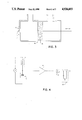
- FIG. 3 is a cross-sectional view of the preferred embodiment.
- FIG. 4 is a schematic representation of the impedance measuring circuit.
- FIG. 5 is the crystal impedance Z plotted versus the interferometric pathlength L.
- FIG. 6 shows the step in the actuator cylinder wall to create a discontinuity in the path of the ultrasonic wave.
- the basic interferometer structure shown in FIG. 1 consists of a piezoelectric crystal 1 and a parallel reflector 2, both immersed in the hydraulic fluid.
- the crystal When the crystal is driven at its resonant frequency by an external source 3, the crystal's electrical impedance becomes sensitive to the input acoustical impedance of the interferometric pathlength L 4.
- any change in the input acoustical impedance of the interferometric path can be detected by monitoring the current drawn by the crystal.
- the reflector is moved, and the interferometric pathlength L is changed, the crystal current reaches alternating maxima and minima.
- the amplitude of the crystal current maxima and minima decreases as the interferometric pathlength is increased due to attenuation in the medium.
- the reflector displacement between adjacent crystal current maxima or minima corresponds to a half-wavelength change in the interferometric wavelength.
- the preferred embodiment of the present invention is a piezoelectric crystal 1 mounted on a Pyrex plate 5 as shown in FIG. 2.
- the structure is mounted within a hydraulic actuator cylinder 6 (which contains a hydraulic oil, or other fluid of relatively low acoustic attenuation) parallel to the target piston 2 as shown in FIG. 3.
- the piezoelectric ceramic of choice is Lead Zirconate Titanate (PZT-5A) which exhibits a high piezoelectric coefficient, a high mechanical Q, and a high Curie temperature.
- PZT-5A Lead Zirconate Titanate
- the crystal mounting requirements are such that the crystal can oscillate with the front surface fixed and the back surface free. In the present case, this is accomplished by bonding the crystal to a thin Pyrex plate that also serves as an intermediate medium which helps to improve the overall acoustic matching between the crystal and the hydraulic fluid.
- the piezoelectric crystal impedance is monitored with the circuit shown in FIG. 4.
- the piezoelectric crystal 1 is placed in series with a known resistor 7.
- the AC voltage across the crystal is fed through a high speed buffer amplitude 8 and converted to a DC voltage with a half-wave rectifier 9 and a low-pass filter 10.
- the invention operates in the following manner:
- the piezoelectric crystal is driven at its resonant frequency as determined by its geometry.
- the crystal impedance Z varies due to the phase shift between the transmitted and the reflected waves within the fluid column of length L as shown in FIG. 5.
- the actuator piston displacement can be monitored. Assuming that both the maximas and the minimas of Z can be detected, the resolution of the invention is ##EQU1##
- the direction of actuator piston movement can be determined by comparing the amplitudes of consecutive crystal impedance maximas. For example in FIG. 5, a decrease in the amplitude of an impedance maxima from the previous impedance maxima indicates actuator piston movement away from the crystal.
- the electrical impedance of the piezoelectric crystal can be monitored as the crystal driving frequency is modulated near the crystal's resonant frequency.
- the crystal impedence Z is maximized at interferometric path lengths equal to integral multiples of half-wavelengths.
- the interferometric path length L 1 is ##EQU2## where n 1 is a dimensionless integer (n 1 >>1) representing the number of half-wavelengths along the interferometric path length L 1 .
- Equation 5 is simply multiplied by the number of resonance peaks less 1, observed in the frequency range of ⁇ f.
- Temperature compensation can be achieved by introducing a discontinuity of the medium in the path of the ultrasonic wave to calibrate the value of the speed of sound in the medium c m which is a function of the temperature.
- the discontinuity of the medium can be achieved by adding a step 13 in the walls of the actuator as shown in FIG. 6. As the driving frequency is swept, the signal reflected from the discontinuity is superimposed onto the signal reflected from the target (resonance). Since the distance from the crystal to the discontinuity is a known constant, the temperature dependent velocity of sound c m in the medium can be determined from (6).
- a temperature monitoring sensor can be placed in the fluid and correction made for the change in the properties of the fluid with temperature. For example a change in the velocity of sound, can be corrected electronically or by using a microprocessor, or by other means.
- Resonance provides for the storage of energy, in this case storage of acoustic energy.
- the relationship between the stored energy and the energy lost through various loss mechanisms is characterized by the quality factor Q.
- the quality factor Q is dependent upon the acoustic losses in the system.
- the loss of acoustic energy in the resonant cavity should be minimized. This can be accomplished by using a low loss acoustic conductive medium in the actuator cylinder. Losses can also be minimized by using special vibrational field configurations, called modes of vibration. These modes are similar to those known in the electromagnetic (microwave resonator and other) arts, as well as in the acoustical art.
- Said modes can be selected by selecting the geometry of the resonant cavity and by location of the acoustic transducer(s).
- the dimensions of the cavity can be small or large. Of special interest for the present invention is actuators of very small size. As an example a cylinder cavity may be 0.5 inches in length and 0.2 inches in diameter. A piston may travel 0.3 inches, and its location may be resolved to approximately +0.001 inches.
- the acoustic transducer may be positioned in one of many possible locations including on one end of the cylinder, the other end or in a sidewall of the cylinder or for that matter on the piston.
- the transducer may be positioned away from the actuator if good acoustic coupling to the actuator is maintained. Piston location to within one mil (or ⁇ 0.001 inches) or less is attainable with a high frequency acoustic transducer (e.g., a 30 MHz transducer), where the resonant quality factor Q is sufficiently high (i.e. when acoustic losses are kept low).
- the actuator dimensions can have different values. Cylinder length of a fraction of an inch and a cylinder diameter of a fraction of an inch are realistic.
- two or more than two frequencies can be used.
- the temperature dependence of the resonance on the temperature dependent velocity of sound (C m ) in the fluid can be eliminated.
- C m temperature dependent velocity of sound
- the use of N different resonant frequencies can be used to determine the values of the N variables.
- the multiple frequencies can be achieved through use of multiple transducers or through the frequency modulation of a single transducer. Since operation is at particular frequencies, narrow band filters may be employed advantageously to exclude ambient noise and to increase the sharpness of the resonance and thus to improve precision of locating the piston position.
- a typical example of dimensions of the device would be piezoelectric transducer of 1/2 inch diameter in a 3/4 inch diameter cylinder.
- the transducer resonant frequency would be 5, 10, or 15 or 30 MHz.
- the resolution counting adjacent peaks at a single resonant frequency of about 15 MHz would be ⁇ 0.001 and ⁇ 20. mils absolute length using adjacent resonances with improved absolute resolution improving by using multiple resonance and transducer frequency modulation.
- the distance from the transducer to the piston in this example would be 0 to 5 inches.
Abstract
Description
Claims (6)
Priority Applications (1)
| Application Number | Priority Date | Filing Date | Title |
|---|---|---|---|
| US07/201,940 US4926693A (en) | 1988-06-03 | 1988-06-03 | Contactless actuator piston proximity sensor |
Applications Claiming Priority (1)
| Application Number | Priority Date | Filing Date | Title |
|---|---|---|---|
| US07/201,940 US4926693A (en) | 1988-06-03 | 1988-06-03 | Contactless actuator piston proximity sensor |
Publications (1)
| Publication Number | Publication Date |
|---|---|
| US4926693A true US4926693A (en) | 1990-05-22 |
Family
ID=22747914
Family Applications (1)
| Application Number | Title | Priority Date | Filing Date |
|---|---|---|---|
| US07/201,940 Expired - Fee Related US4926693A (en) | 1988-06-03 | 1988-06-03 | Contactless actuator piston proximity sensor |
Country Status (1)
| Country | Link |
|---|---|
| US (1) | US4926693A (en) |
Cited By (15)
| Publication number | Priority date | Publication date | Assignee | Title |
|---|---|---|---|---|
| WO1997032138A1 (en) * | 1996-03-01 | 1997-09-04 | Emg-Eltma Gmbh | Electrohydraulic lifting device |
| EP0949193A2 (en) * | 1998-04-10 | 1999-10-13 | Kabushiki Kaisha Toyoda Jidoshokki Seisakusho | Lift cylinder and mast assembly of forklift |
| US6397745B2 (en) * | 1996-09-30 | 2002-06-04 | Accel Graphic Systems, Inc. | Method and apparatus for maintaining ink level in ink fountain of printing press |
| US20030005816A1 (en) * | 2001-01-12 | 2003-01-09 | Protune Corp. | Self-aligning ultrasonic displacement sensor system, apparatus and method for detecting surface vibrations |
| US20050014178A1 (en) * | 2003-05-22 | 2005-01-20 | Holm-Kennedy James W. | Ultrasensitive biochemical sensor |
| US20050208647A1 (en) * | 2004-03-18 | 2005-09-22 | Holm-Kennedy James W | Biochemical concentrator and drug discovery |
| US20050224346A1 (en) * | 2003-10-31 | 2005-10-13 | Holm-Kennedy James W | Ultrasensitive biochemical sensing platform |
| US20050250272A1 (en) * | 2004-05-03 | 2005-11-10 | Holm-Kennedy James W | Biosensor performance enhancement features and designs |
| WO2007082834A1 (en) * | 2006-01-13 | 2007-07-26 | Robert Bosch Gmbh | Measuring device, in particular distance measuring device |
| US20080168840A1 (en) * | 2007-01-12 | 2008-07-17 | Lockheed Martin Corporation | Low-power shock and vibration sensors and methods of making sensors |
| US7692219B1 (en) | 2004-06-25 | 2010-04-06 | University Of Hawaii | Ultrasensitive biosensors |
| WO2012038686A1 (en) | 2010-09-21 | 2012-03-29 | Rolls-Royce Goodrich Engine Control Systems Ltd | Position sensor |
| GB2518060B (en) * | 2012-04-27 | 2016-04-27 | Cameron Int Corp | Position monitoring system and method |
| US20170153437A1 (en) * | 2015-06-30 | 2017-06-01 | General Electric Company | Optical microscope and method for detecting lens immersion |
| US10823850B2 (en) * | 2016-12-01 | 2020-11-03 | Illinois Tool Works Inc. | Measuring device |
Citations (5)
| Publication number | Priority date | Publication date | Assignee | Title |
|---|---|---|---|---|
| US3108469A (en) * | 1959-08-04 | 1963-10-29 | Cutler Hammer Inc | Non-contacting ultrasonic gage |
| US4420727A (en) * | 1981-10-01 | 1983-12-13 | Burroughs Corporation | Self oscillating acoustic displacement detector |
| US4512194A (en) * | 1981-04-01 | 1985-04-23 | Battelle-Institut E.V. | Method and apparatus for controlling or measuring the thickness of material layers |
| US4542652A (en) * | 1982-03-30 | 1985-09-24 | Martin Reuter | Method and apparatus for determining a relative distance in a cylinder and piston assembly |
| US4543649A (en) * | 1983-10-17 | 1985-09-24 | Teknar, Inc. | System for ultrasonically detecting the relative position of a moveable device |
-
1988
- 1988-06-03 US US07/201,940 patent/US4926693A/en not_active Expired - Fee Related
Patent Citations (5)
| Publication number | Priority date | Publication date | Assignee | Title |
|---|---|---|---|---|
| US3108469A (en) * | 1959-08-04 | 1963-10-29 | Cutler Hammer Inc | Non-contacting ultrasonic gage |
| US4512194A (en) * | 1981-04-01 | 1985-04-23 | Battelle-Institut E.V. | Method and apparatus for controlling or measuring the thickness of material layers |
| US4420727A (en) * | 1981-10-01 | 1983-12-13 | Burroughs Corporation | Self oscillating acoustic displacement detector |
| US4542652A (en) * | 1982-03-30 | 1985-09-24 | Martin Reuter | Method and apparatus for determining a relative distance in a cylinder and piston assembly |
| US4543649A (en) * | 1983-10-17 | 1985-09-24 | Teknar, Inc. | System for ultrasonically detecting the relative position of a moveable device |
Cited By (31)
| Publication number | Priority date | Publication date | Assignee | Title |
|---|---|---|---|---|
| WO1997032138A1 (en) * | 1996-03-01 | 1997-09-04 | Emg-Eltma Gmbh | Electrohydraulic lifting device |
| US6397745B2 (en) * | 1996-09-30 | 2002-06-04 | Accel Graphic Systems, Inc. | Method and apparatus for maintaining ink level in ink fountain of printing press |
| US6401612B2 (en) | 1996-09-30 | 2002-06-11 | Accel Graphic Systems, Inc. | Method and apparatus for maintaining ink level in ink fountain of printing press |
| US6619206B2 (en) | 1996-09-30 | 2003-09-16 | Accel Graphic Systems, Inc. | Method and apparatus for maintaining ink level in ink fountain of printing press |
| EP0949193A2 (en) * | 1998-04-10 | 1999-10-13 | Kabushiki Kaisha Toyoda Jidoshokki Seisakusho | Lift cylinder and mast assembly of forklift |
| EP0949193A3 (en) * | 1998-04-10 | 2004-01-28 | Kabushiki Kaisha Toyota Jidoshokki | Lift cylinder and mast assembly of forklift |
| US20030005816A1 (en) * | 2001-01-12 | 2003-01-09 | Protune Corp. | Self-aligning ultrasonic displacement sensor system, apparatus and method for detecting surface vibrations |
| US6809249B2 (en) * | 2001-01-12 | 2004-10-26 | Protune Corp. | Self-aligning ultrasonic displacement sensor system, apparatus and method for detecting surface vibrations |
| US7291496B2 (en) | 2003-05-22 | 2007-11-06 | University Of Hawaii | Ultrasensitive biochemical sensor |
| US20050014178A1 (en) * | 2003-05-22 | 2005-01-20 | Holm-Kennedy James W. | Ultrasensitive biochemical sensor |
| USRE43978E1 (en) | 2003-05-22 | 2013-02-05 | University Of Hawaii | Ultrasensitive biochemical sensor |
| US7317216B2 (en) | 2003-10-31 | 2008-01-08 | University Of Hawaii | Ultrasensitive biochemical sensing platform |
| US20050224346A1 (en) * | 2003-10-31 | 2005-10-13 | Holm-Kennedy James W | Ultrasensitive biochemical sensing platform |
| US8192966B2 (en) | 2004-03-18 | 2012-06-05 | University Of Hawaii | Biochemical concentrator and drug discovery |
| US20050208647A1 (en) * | 2004-03-18 | 2005-09-22 | Holm-Kennedy James W | Biochemical concentrator and drug discovery |
| US7566418B2 (en) | 2004-03-18 | 2009-07-28 | University Of Hawaii | Biochemical concentrator and drug discovery |
| US20050250272A1 (en) * | 2004-05-03 | 2005-11-10 | Holm-Kennedy James W | Biosensor performance enhancement features and designs |
| US8536661B1 (en) | 2004-06-25 | 2013-09-17 | University Of Hawaii | Biosensor chip sensor protection methods |
| US7692219B1 (en) | 2004-06-25 | 2010-04-06 | University Of Hawaii | Ultrasensitive biosensors |
| US10563252B2 (en) | 2004-06-25 | 2020-02-18 | University Of Hawaii | Ultrasensitive biosensors |
| WO2007082834A1 (en) * | 2006-01-13 | 2007-07-26 | Robert Bosch Gmbh | Measuring device, in particular distance measuring device |
| CN101371100B (en) * | 2006-01-13 | 2012-05-02 | 罗伯特.博世有限公司 | Measuring device |
| US20100235128A1 (en) * | 2006-01-13 | 2010-09-16 | Peter Wolf | Measuring device, in particular distance measuring device |
| US20080168840A1 (en) * | 2007-01-12 | 2008-07-17 | Lockheed Martin Corporation | Low-power shock and vibration sensors and methods of making sensors |
| US8443672B2 (en) * | 2007-01-12 | 2013-05-21 | Lockheed Martin Corporation | Low-power shock and vibration sensors and methods of making sensors |
| WO2012038686A1 (en) | 2010-09-21 | 2012-03-29 | Rolls-Royce Goodrich Engine Control Systems Ltd | Position sensor |
| GB2518060B (en) * | 2012-04-27 | 2016-04-27 | Cameron Int Corp | Position monitoring system and method |
| NO344024B1 (en) * | 2012-04-27 | 2019-08-19 | Cameron Tech Ltd | Position monitoring system and method |
| US20170153437A1 (en) * | 2015-06-30 | 2017-06-01 | General Electric Company | Optical microscope and method for detecting lens immersion |
| US9977231B2 (en) * | 2015-06-30 | 2018-05-22 | General Electric Company | Optical microscope and method for detecting lens immersion |
| US10823850B2 (en) * | 2016-12-01 | 2020-11-03 | Illinois Tool Works Inc. | Measuring device |
Similar Documents
| Publication | Publication Date | Title |
|---|---|---|
| US4926693A (en) | Contactless actuator piston proximity sensor | |
| US4193010A (en) | Sensor device using piezoelectric coating subjected to bending | |
| Manthey et al. | Ultrasonic transducers and transducer arrays for applications in air | |
| US4806859A (en) | Resonant vibrating structures with driving sensing means for noncontacting position and pick up sensing | |
| US4712037A (en) | Resonant piezoelectric sensor | |
| US5668303A (en) | Sensor having a membrane as part of an electromechanical resonance circuit forming receiver and transmitter converter with interdigital structures spaced apart from one another | |
| EP0395008B1 (en) | Cylinders having piston position measurement | |
| US5323638A (en) | Sensor apparatus | |
| EP1837638B1 (en) | Pressure sensor | |
| US4650346A (en) | Arrangement for ultrasonic temperature measurement using a resonant sensor | |
| US4117716A (en) | Densitometer apparatus | |
| US4098133A (en) | Vibrating diaphragm fluid pressure sensor device | |
| JP2007256287A (en) | Pressure sensor | |
| JPS639169B2 (en) | ||
| US4676663A (en) | Arrangement for remote ultrasonic temperature measurement | |
| Wu et al. | Tuning characteristics of AlN-based piezoelectric micromachined ultrasonic transducers using DC bias voltage | |
| GB1581291A (en) | Sensor device | |
| US5302878A (en) | High-frequency acoustic rheometer and device to measure the viscosity of a fluid using this rheometer | |
| JP5658061B2 (en) | Mechanical quantity sensor | |
| US20220291302A1 (en) | Measuring device for weak and slowly changing magnetic fields, in particular for biomagnetic fields | |
| JPH04500273A (en) | Angular velocity detection sensor | |
| JP3880047B2 (en) | Ultrasonic sensor | |
| Tapson | High precision, short range ultrasonic sensing by means of resonance mode-locking | |
| JP3006861U (en) | Ultrasonic probe | |
| JPH03505919A (en) | Fill level indicator |
Legal Events
| Date | Code | Title | Description |
|---|---|---|---|
| AS | Assignment |
Owner name: RESEARCH CORPORATION OF THE UNIVERSITY OF HAWAII, Free format text: ASSIGNMENT OF ASSIGNORS INTEREST.;ASSIGNORS:HOLM-KENNEDY, JAMES W.;KAWAMOTO, ERIC H.;BOPP, THOMAS T.;REEL/FRAME:004905/0491 Effective date: 19880601 Owner name: RESEARCH CORPORATION OF THE UNIVERSITY OF HAWAII, Free format text: ASSIGNMENT OF ASSIGNORS INTEREST;ASSIGNORS:HOLM-KENNEDY, JAMES W.;KAWAMOTO, ERIC H.;BOPP, THOMAS T.;REEL/FRAME:004905/0491 Effective date: 19880601 |
|
| AS | Assignment |
Owner name: UNIVERSITY OF HAWAII, HAWAII Free format text: ASSIGNMENT OF ASSIGNORS INTEREST.;ASSIGNOR:RESEARCH CORPORATION OF THE UNIVERSITY OF HAWAII;REEL/FRAME:005450/0734 Effective date: 19900913 |
|
| FEPP | Fee payment procedure |
Free format text: PAYOR NUMBER ASSIGNED (ORIGINAL EVENT CODE: ASPN); ENTITY STATUS OF PATENT OWNER: SMALL ENTITY |
|
| FPAY | Fee payment |
Year of fee payment: 4 |
|
| FPAY | Fee payment |
Year of fee payment: 8 |
|
| REMI | Maintenance fee reminder mailed | ||
| LAPS | Lapse for failure to pay maintenance fees | ||
| STCH | Information on status: patent discontinuation |
Free format text: PATENT EXPIRED DUE TO NONPAYMENT OF MAINTENANCE FEES UNDER 37 CFR 1.362 |
|
| FP | Lapsed due to failure to pay maintenance fee |
Effective date: 20020522 |