US4924853A - Stereoscopic medical viewing device - Google Patents
Stereoscopic medical viewing device Download PDFInfo
- Publication number
- US4924853A US4924853A US07/354,761 US35476189A US4924853A US 4924853 A US4924853 A US 4924853A US 35476189 A US35476189 A US 35476189A US 4924853 A US4924853 A US 4924853A
- Authority
- US
- United States
- Prior art keywords
- probe
- transmission elements
- images
- viewing system
- image
- Prior art date
- Legal status (The legal status is an assumption and is not a legal conclusion. Google has not performed a legal analysis and makes no representation as to the accuracy of the status listed.)
- Expired - Fee Related
Links
- 230000005540 biological transmission Effects 0.000 claims abstract description 50
- 239000000523 sample Substances 0.000 claims abstract description 40
- 230000003287 optical effect Effects 0.000 claims abstract description 22
- 239000000835 fiber Substances 0.000 claims description 7
- 239000011521 glass Substances 0.000 claims description 5
- 230000000007 visual effect Effects 0.000 claims description 4
- 230000000694 effects Effects 0.000 claims description 3
- 238000000034 method Methods 0.000 claims description 2
- 210000000746 body region Anatomy 0.000 abstract description 7
- 238000001356 surgical procedure Methods 0.000 description 5
- 238000006243 chemical reaction Methods 0.000 description 2
- 238000004140 cleaning Methods 0.000 description 2
- 230000001427 coherent effect Effects 0.000 description 2
- 238000013461 design Methods 0.000 description 2
- 230000006870 function Effects 0.000 description 2
- 238000000926 separation method Methods 0.000 description 2
- 230000000903 blocking effect Effects 0.000 description 1
- 150000001875 compounds Chemical class 0.000 description 1
- 230000008878 coupling Effects 0.000 description 1
- 238000010168 coupling process Methods 0.000 description 1
- 238000005859 coupling reaction Methods 0.000 description 1
- 239000003814 drug Substances 0.000 description 1
- 238000005516 engineering process Methods 0.000 description 1
- 239000012530 fluid Substances 0.000 description 1
- 238000005286 illumination Methods 0.000 description 1
- 238000003780 insertion Methods 0.000 description 1
- 230000037431 insertion Effects 0.000 description 1
- 238000007689 inspection Methods 0.000 description 1
- 230000002262 irrigation Effects 0.000 description 1
- 238000003973 irrigation Methods 0.000 description 1
- 239000007788 liquid Substances 0.000 description 1
- 239000004973 liquid crystal related substance Substances 0.000 description 1
- 238000004519 manufacturing process Methods 0.000 description 1
- 238000012986 modification Methods 0.000 description 1
- 230000004048 modification Effects 0.000 description 1
- 238000012544 monitoring process Methods 0.000 description 1
- 210000000056 organ Anatomy 0.000 description 1
- 230000035807 sensation Effects 0.000 description 1
- 238000005549 size reduction Methods 0.000 description 1
- 230000001360 synchronised effect Effects 0.000 description 1
Images

Classifications
-
- G—PHYSICS
- G02—OPTICS
- G02B—OPTICAL ELEMENTS, SYSTEMS OR APPARATUS
- G02B23/00—Telescopes, e.g. binoculars; Periscopes; Instruments for viewing the inside of hollow bodies; Viewfinders; Optical aiming or sighting devices
- G02B23/24—Instruments or systems for viewing the inside of hollow bodies, e.g. fibrescopes
- G02B23/2407—Optical details
- G02B23/2415—Stereoscopic endoscopes
-
- A—HUMAN NECESSITIES
- A61—MEDICAL OR VETERINARY SCIENCE; HYGIENE
- A61B—DIAGNOSIS; SURGERY; IDENTIFICATION
- A61B1/00—Instruments for performing medical examinations of the interior of cavities or tubes of the body by visual or photographical inspection, e.g. endoscopes; Illuminating arrangements therefor
- A61B1/00163—Optical arrangements
- A61B1/00193—Optical arrangements adapted for stereoscopic vision
-
- A—HUMAN NECESSITIES
- A61—MEDICAL OR VETERINARY SCIENCE; HYGIENE
- A61B—DIAGNOSIS; SURGERY; IDENTIFICATION
- A61B1/00—Instruments for performing medical examinations of the interior of cavities or tubes of the body by visual or photographical inspection, e.g. endoscopes; Illuminating arrangements therefor
- A61B1/00163—Optical arrangements
- A61B1/00194—Optical arrangements adapted for three-dimensional imaging
-
- A—HUMAN NECESSITIES
- A61—MEDICAL OR VETERINARY SCIENCE; HYGIENE
- A61B—DIAGNOSIS; SURGERY; IDENTIFICATION
- A61B1/00—Instruments for performing medical examinations of the interior of cavities or tubes of the body by visual or photographical inspection, e.g. endoscopes; Illuminating arrangements therefor
- A61B1/04—Instruments for performing medical examinations of the interior of cavities or tubes of the body by visual or photographical inspection, e.g. endoscopes; Illuminating arrangements therefor combined with photographic or television appliances
- A61B1/042—Instruments for performing medical examinations of the interior of cavities or tubes of the body by visual or photographical inspection, e.g. endoscopes; Illuminating arrangements therefor combined with photographic or television appliances characterised by a proximal camera, e.g. a CCD camera
-
- A—HUMAN NECESSITIES
- A61—MEDICAL OR VETERINARY SCIENCE; HYGIENE
- A61B—DIAGNOSIS; SURGERY; IDENTIFICATION
- A61B1/00—Instruments for performing medical examinations of the interior of cavities or tubes of the body by visual or photographical inspection, e.g. endoscopes; Illuminating arrangements therefor
- A61B1/313—Instruments for performing medical examinations of the interior of cavities or tubes of the body by visual or photographical inspection, e.g. endoscopes; Illuminating arrangements therefor for introducing through surgical openings, e.g. laparoscopes
- A61B1/317—Instruments for performing medical examinations of the interior of cavities or tubes of the body by visual or photographical inspection, e.g. endoscopes; Illuminating arrangements therefor for introducing through surgical openings, e.g. laparoscopes for bones or joints, e.g. osteoscopes, arthroscopes
Definitions
- This invention relates to an arthroscope for viewing the internal structure or condition of a human or animal joint.
- Arthroscopes belong to a class of medical instruments, called endoscopes, that enable physicians to examine, or perform surgery on, various organs and interior body cavities.
- Arthroscopes utilize a thin, elongated probe for insertion into or near the region or joint to be examined. Light is transmitted to the inserted (distal) end of the probe, to illuminate the region under observation. An image transmission device, using this light, transmits to the observing physician a view of the region.
- a light tube or optic fiber bundle is conventionally used to illuminate the region being observed. If an optic fiber bundle is used, an incoherent bundle will suffice. Transmission of an image from the observed region to the observer, however, requires a coherent bundle.
- the distal end of the instrument is covered by a lens, which focuses images to be viewed on the ends of the optic fibers in the bundle or transmits these images to a glass image transmission rod.
- Arthroscopes are usually equipped with irrigation passages for supplying cleaning liquid to the outside distal end of the probe and keeping it clear for viewing. Air is sometimes also supplied through passages in the probe for the same purpose.
- surgical tools can be inserted into an interior body region through an arthroscope probe.
- Still another object of the invention is to provide a method for viewing a three-dimensional image of an interior body region, whereby visual images of the region are converted to electrical signals and displayed on a television screen.
- the present invention for achieving these and other objects is an arthroscope in which optically conductive fiber bundles, glass rods, or their equivalents, transmit light through the probe to its distal end, to illuminate the interior body region under observation.
- the side-by-side image transmission elements may terminate at the distal end of the probe at an angle of between 25° and 30° away from the longitudinal axis of the probe.
- the distal end of the probe terminates at the same angle, to guard against any blocking of the images received by the image transmission elements.
- This view as provided by the image transmission elements is directed or tilted to the side, i.e., away from the longitudinal axis of the probe, at an angle of between 25°-30°; i.e., at the same angle at which the ends of the light transmission elements and the probe are terminated.
- two parallel image transmission elements are necessary to obtain the desired three dimensional effect.
- the fields of view of the image transmission elements are ordinarily fixed to converge at a distance of about 2.5 cm from their distal ends, although this convergence may be varied.
- the images are optically transmitted by the image transmission elements to a prism system, rotatable with the probe. This synchronous rotation of the prism system and the image transmission elements maintains the view of the observed region upright, regardless of the amount of rotation.
- a common optical axis the longitudinal axis of the probe
- Prismatic systems are often used for this purpose.
- the merged image is viewed by looking through a collimating eye piece or compound lens arrangement.
- the optical images of the viewed region are converted to electrical signals by a photo-detector or its equivalent. These electrical signals are used to produce three-dimensional images on a television screen.
- images from each image transmission element are not simultaneously transmitted to the signal input circuitry of the television monitor. Rather, they are sequentially transmitted, this sequential transmission being controlled by shutters within the prism system.
- Such sequential transmissions of the electrical images may be achieved by a particular interlacing of images from each image transmission element, as described in U.S. Pat. No. 4,528,587, to Jones, a co-inventor of this invention, or by the alternating transmission of images from each image transmission element, as in U.S. Pat. No. 4,429,328, to Jones, McLaurin and Cathey, the first two of whom are the joint inventors of this invention.
- the switching rate between images is selected in accordance with the teachings of these patents. It is also explained in each patent how the switching rate can be set to take into account the 60 Hertz cathode ray beam sweep rate used for commercial television broadcasting.
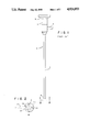
- FIG. 1 is a side elevation view of a prior art arthroscope.
- FIG. 2 is a greatly enlarged transverse end view of the distal end of the arthroscope used in this invention, taken along lines 2-2 of FIG. 1.
- FIG. 3 is a longitudinal sectional view of the arthroscope used in this invention, including a prismatic arrangement for merging the images received from the distal end of each image transmission element.
- FIG. 4 is a schematic illustration of the elements and circuitry of this invention for producing from the output of an arthroscope a three-dimensional view on a standard television screen.
- the invention includes an arthroscope and associated television system for viewing in three dimensions the interior of a body part or region, and a method for producing these views on a television screen.
- the arthroscope 2 includes an elongated hollow probe 4, of tubular form, having a distal end 6.
- the probe contains two parallel or side-by-side image transmission elements. These elements transmit to the user of the instrument images of the region or body part under observation.
- the viewing (user's) end of the arthroscope includes a prismatic arrangement 12 (FIG. 3) contained in a housing 14 (FIG. 1). This prismatic arrangement is positioned in the optical path between the viewing ends of the image transmission elements and the collimating lens 10.
- the lens 10 is coupled to the prism system through optical coupling section 8, of conventional design.
- a light entry port 16 is optically connected to the probe, to provide viewing light at the distal end of the arthroscope. Usually, this is done by use of optic fiber bundles extending through passages or tubes within the probe.
- the arthroscope may contain other conventional components, including fluid ports for cleaning the distal region and laser scalpels or other instruments.
- FIG. 2 taken along lines 2--2 of FIG. 1, depicts the distal end of the arthroscope.
- the two image transmission elements 18 and 18, are also contained within a tube 20.
- the tube 20 is, in turn, contained within probe 4.
- Other physical arrangements, as known in the prior art, could alternatively be used.
- These image transmission elements are optically coupled to the prismatic arrangement 12.
- the image transmission elements 18 and 18' may vary in diameter, but diameters of about 2 mm each are typically used. A separation of about 0.5 mm between the image transmission elements provides a satisfactory depth or three-dimensional sensation, when the images are converted to electrical signals and displayed on a television monitor. This separation may be varied, however, so long as the light transmission elements do not touch.
- the distal end 6 of the probe 4, as seen in FIG. 1, is terminated at an angle of about 25° to 30°.
- the elements 18 and 18, are terminated at the same angle as is the containing tube 20.
- rotation of the arthroscope along its longitudinal axis allows the surgeon also to look off to the side.
- the instrument will view the region at a tilt of 25° to 30° from its longitudinal axis and the surgeon is not limited to a straight-ahead view.
- This viewing angle could, however, vary from 0° (straight ahead) to 60°, for special applications, although a tilt of 25°-30° is more typical.
- the tube 4 could be made flexible for some applications.
- the curvature of the tube might be changed during use by an internally located wire connected at one end to the distal end of the tube. Such curvature adjusting means are known.
- the image transmission elements are shown in vertical alignment in FIG. 2, but this alignment obviously changes as the arthroscope is rotated in use.
- the ends of the image transmission elements are additionally oriented at a slight angle toward each other, so that the fields of view 22 and 24 of each converge at a distance of about 2.5 cm from their distal ends. Other distances of convergence may, however, be selected, depending on the use to which the instrument is put.
- Illumination of the viewing region is provided by illuminating fiber bundles 26, which, in this embodiment, also extend through tube 20. Bundles 26 are optically coupled in a conventional manner to light entry port 16. Glass rods or other light transmitting elements could also be used.
- FIG. 3 illustrates the parallel optical paths of the images transmitted by image transmitting elements 18 and 18, from their distal ends to the collimating element 10. These elements are each optically coupled to the prismatic arrangement 12, so that light from each element enters, respectively, the associated bottom face of parallelogram-shaped prisms 30 and 30,.
- each image can be opened and closed by shutters 32 and 32, In the embodiments of the invention illustrated in FIG. 3, these shutters remain continually open, or may be eliminated entirely.
- the shutters are needed for the embodiment of FIG. 4, however, and the presentation of three-dimensional images.
- Prism 36 also functions as a split beam device, diagrammatically represented by dotted line 38.
- This split beam prism 36 redirects the images from prisms 34 and 34' through a collimating means 10.
- the images, upon leaving prism 36, are projected along an optical path coinciding with the longitudinal axis of the probe 4.
- the prismatic arrangement in this way, converts a binocular image, i.e. an image taken from two points of origin or two points of view within a body cavity, to a converging (monocular) image.
- Optical systems for converting monocular to binocular (but not three-dimensional) images are known, for example, the Leitz lens system.
- the system of this invention uses these known optical systems in a completely different way, i.e. by converting binocular to monocular images.
- the optical path of each image is, therefore, opposite or reversed from those in prior art systems.
- FIG. 4 schematically illustrates the operation of the shutters, the conversion of transmitted optical images to electrical pulses and the three-dimensional display on a television screen of images generated from these pulses.
- the creation of a three-dimensional display is explained in the above-mentioned United States patents to Jones ('587) and Jones et al ('328).
- the image or view to be depicted in three dimensions must be alternately presented on the television screen according to a particular sequence or pattern.
- the sequences in either of these patents are, in general, created by the alternate viewing of the image first from one point or origin and then from another. These points of origin are the distal ends of the image transmission elements.
- the three-dimensional systems described in these two patents are collectively known as the "Visidep" system.
- images from each point of origin are obtained by cameras positioned at these points.
- the shutters 32 and 32' serve the function of the two cameras in providing alternating or sequential images from two points of origin (the distal ends of elements 18 and 18').
- the shutters need not be of any particular type, so long as they are capable of operating at a switching rate of from 8 to 15 times per second.
- Electro-optic, liquid crystal or mechanical shutters can be used.
- shutters 32 and 32' are controlled by a switching network 40.
- This switching network is, in turn, controlled by a pulse generator 42. Therefore, these system components serve the identical purpose as the corresponding components 14 and 16 in either of the two above-mentioned patents.
- photodetector 44 which may be a charge-coupled device (CCD) or other device well known for this purpose. It replaces the collinating lens 10 illustrated in FIG. 3.
- CCD charge-coupled device
- the photodetector output is provided to a television monitor 46, on which the viewed region is displayed in three dimensions.
- the invention has been described as an arthroscope, it should be apparent that it has application in all endoscopic devices, including gastroscopes, proctoscopes, laproscopes and cystoscopes. It should further be understood that the uses of the invention are not limited to medicine. It could be used, for example, to inspect the interior of tubing or pipes in a nuclear reactor or other devices or systems where disassembly is expensive or impractical.
Abstract
Description
Claims (16)
Priority Applications (3)
| Application Number | Priority Date | Filing Date | Title |
|---|---|---|---|
| US07/354,761 US4924853A (en) | 1989-05-22 | 1989-05-22 | Stereoscopic medical viewing device |
| PCT/US1990/002252 WO1990014040A1 (en) | 1989-05-22 | 1990-04-30 | Stereoscopic medical viewing device |
| AU55629/90A AU5562990A (en) | 1989-05-22 | 1990-04-30 | Stereoscopic medical viewing device |
Applications Claiming Priority (1)
| Application Number | Priority Date | Filing Date | Title |
|---|---|---|---|
| US07/354,761 US4924853A (en) | 1989-05-22 | 1989-05-22 | Stereoscopic medical viewing device |
Publications (1)
| Publication Number | Publication Date |
|---|---|
| US4924853A true US4924853A (en) | 1990-05-15 |
Family
ID=23394810
Family Applications (1)
| Application Number | Title | Priority Date | Filing Date |
|---|---|---|---|
| US07/354,761 Expired - Fee Related US4924853A (en) | 1989-05-22 | 1989-05-22 | Stereoscopic medical viewing device |
Country Status (3)
| Country | Link |
|---|---|
| US (1) | US4924853A (en) |
| AU (1) | AU5562990A (en) |
| WO (1) | WO1990014040A1 (en) |
Cited By (38)
| Publication number | Priority date | Publication date | Assignee | Title |
|---|---|---|---|---|
| DE4213584A1 (en) * | 1991-04-24 | 1992-11-05 | Olympus Optical Co | Medical arrangement with object information reproduction device - detects state of part and displays it to surgeon operating medical device |
| US5222477A (en) * | 1991-09-30 | 1993-06-29 | Welch Allyn, Inc. | Endoscope or borescope stereo viewing system |
| US5295477A (en) * | 1992-05-08 | 1994-03-22 | Parviz Janfaza | Endoscopic operating microscope |
| DE4405102A1 (en) * | 1993-02-17 | 1994-08-25 | Olympus Optical Co | Stereoscopic endoscope |
| US5381784A (en) * | 1992-09-30 | 1995-01-17 | Adair; Edwin L. | Stereoscopic endoscope |
| US5385138A (en) * | 1992-01-21 | 1995-01-31 | Berry; Yale | Stereo endoscope for inserting into body cavities |
| GB2280514A (en) * | 1993-07-26 | 1995-02-01 | Keymed | A borescope |
| US5474519A (en) * | 1994-05-10 | 1995-12-12 | Bloomer; William E. | Method for obtaining stereoscopic imagery from a pair of endoscopes |
| WO1996002114A1 (en) * | 1994-07-08 | 1996-01-25 | Forschungszentrum Karlsruhe Gmbh | 3d video endoscope |
| US5495114A (en) * | 1992-09-30 | 1996-02-27 | Adair; Edwin L. | Miniaturized electronic imaging chip |
| US5522789A (en) * | 1992-12-24 | 1996-06-04 | Olympus Optical Co., Ltd. | Stereo endoscope and stereo endoscope imaging apparatus |
| US5538497A (en) * | 1992-10-28 | 1996-07-23 | Oktas | Endoscope having parasitic light elements |
| US5577991A (en) * | 1992-06-09 | 1996-11-26 | Olympus Optical Co., Ltd. | Three-dimensional vision endoscope with position adjustment means for imaging device and visual field mask |
| US5603687A (en) * | 1992-10-28 | 1997-02-18 | Oktas General Partnership | Asymmetric stereo-optic endoscope |
| US5751341A (en) * | 1993-01-05 | 1998-05-12 | Vista Medical Technologies, Inc. | Stereoscopic endoscope system |
| US5828487A (en) * | 1994-04-14 | 1998-10-27 | International Telepresence (Canada) Inc. | Stereoscopic viewing system using a two dimensional lens system |
| US5846185A (en) * | 1996-09-17 | 1998-12-08 | Carollo; Jerome T. | High resolution, wide field of view endoscopic viewing system |
| US5919128A (en) * | 1997-06-18 | 1999-07-06 | The Regents Of The University Of California | Sparse aperture endoscope |
| US5944655A (en) * | 1994-07-08 | 1999-08-31 | Forschunjszentrum Karlsruhe Gmbh | 3D endoscope with optical switch and prism arrangement |
| US5964696A (en) * | 1996-10-24 | 1999-10-12 | Smith & Nephew, Inc. | Stereoscopic imaging by alternately blocking light |
| US6139490A (en) * | 1996-02-22 | 2000-10-31 | Precision Optics Corporation | Stereoscopic endoscope with virtual reality viewing |
| US6239908B1 (en) | 1998-11-12 | 2001-05-29 | Shawn L. Kelly | Compact binocular imaging system using a single display |
| US6582358B2 (en) * | 2000-09-12 | 2003-06-24 | Olympus Optical Co., Ltd. | Stereoscopic endoscope system |
| US6614595B2 (en) | 2001-02-16 | 2003-09-02 | Olympus Optical Co., Ltd. | Stereo endoscope |
| FR2850465A1 (en) * | 2003-01-29 | 2004-07-30 | Jacques Marie Pierre Chamagne | Large screen film three dimensional image format camera having single unit with two optical filters/lens aligned producing eye offset providing three dimensional moving/static view |
| US20060074289A1 (en) * | 2004-08-26 | 2006-04-06 | Doron Adler | Wireless determination of endoscope orientation |
| WO2007132378A3 (en) * | 2006-05-09 | 2008-01-24 | Koninkl Philips Electronics Nv | Imaging system for three-dimensional imaging of the interior of an object |
| US20080125629A1 (en) * | 2004-08-26 | 2008-05-29 | Boston Scientific Scimed, Inc. | Endoscope having auto-insufflation and exsufflation |
| US20080151041A1 (en) * | 2006-12-21 | 2008-06-26 | Intuitive Surgical, Inc. | Stereoscopic endoscope |
| US20090112061A1 (en) * | 2007-10-25 | 2009-04-30 | Dhs Company Ltd. | Endoscope capable of varying field of vision |
| US20100261961A1 (en) * | 2006-12-21 | 2010-10-14 | Intuitive Surgical Operations, Inc. | Hermetically sealed distal sensor endoscope |
| DE102010054666A1 (en) * | 2010-12-15 | 2012-06-21 | Olympus Winter & Ibe Gmbh | Fiber light conductor for video endoscope, has irradiating end connected with light source comprising rectangular light exit surface, where light source comprises LEDs and front surface of conductor is rectangular at irradiating end |
| EP2492744A1 (en) * | 2009-10-23 | 2012-08-29 | Olympus Medical Systems Corp. | Objective optical system for three-dimensional image capturing and endoscope |
| CN103006170A (en) * | 2012-12-16 | 2013-04-03 | 天津大学 | Medical endoscope three-dimensional imaging device |
| US20140293415A1 (en) * | 2011-10-28 | 2014-10-02 | Scholly Fiberoptic Gmbh | Endoscope |
| US9298078B2 (en) | 2009-07-10 | 2016-03-29 | Steropes Technologies, Llc | Method and apparatus for generating three-dimensional image information using a single imaging path |
| US9798131B2 (en) | 2014-12-23 | 2017-10-24 | Visionsense Ltd. | Rotatable oblique-viewing stereoendoscope |
| CN109008925A (en) * | 2018-08-06 | 2018-12-18 | 卢雅艳 | A kind of integrated type electrical laryngoscope for realizing three-dimensional imaging |
Families Citing this family (3)
| Publication number | Priority date | Publication date | Assignee | Title |
|---|---|---|---|---|
| US5459605A (en) * | 1992-12-17 | 1995-10-17 | Paul S. Kempf | 3-D endoscope apparatus |
| US5423312A (en) * | 1992-12-18 | 1995-06-13 | Schott Fiber Optics, Inc. | Rigid endoscope having modified high refractive index tunnel rod for image transmission and method of manufacture thereof |
| WO1996037796A1 (en) | 1995-05-24 | 1996-11-28 | Olympus Optical Co., Ltd. | Stereoscopic endoscope system and tv image pickup system for the endoscope |
Citations (13)
| Publication number | Priority date | Publication date | Assignee | Title |
|---|---|---|---|---|
| US3067648A (en) * | 1959-10-05 | 1962-12-11 | Samuel W Cohen | Optical instrument with binocular viewing attachment |
| US3994557A (en) * | 1974-02-20 | 1976-11-30 | The Secretary Of State For Social Services In Her Brittanic Majesty's Government Of The United Kingdom Of Great Britain And Northern Ireland | Optical systems |
| US4061135A (en) * | 1976-09-27 | 1977-12-06 | Jerrold Widran | Binocular endoscope |
| US4259948A (en) * | 1978-11-13 | 1981-04-07 | Peter Urban | Endoscopic system |
| US4413278A (en) * | 1981-10-05 | 1983-11-01 | Designs For Vision, Inc. | Optical coupling apparatus for coupling an arthoscope to a camera |
| US4429328A (en) * | 1981-07-16 | 1984-01-31 | Cjm Associates | Three-dimensional display methods using vertically aligned points of origin |
| US4528587A (en) * | 1982-10-28 | 1985-07-09 | Cjm Associates | Three-dimensional video apparatus and methods using composite and mixed images |
| US4576147A (en) * | 1981-07-16 | 1986-03-18 | Olympus Optical Co., Ltd. | Hard endoscope with improved light dispersion |
| US4589404A (en) * | 1984-01-03 | 1986-05-20 | Medical Dynamics, Inc. | Laser endoscope |
| US4590923A (en) * | 1983-04-18 | 1986-05-27 | Watanabe Robert S | Arthroscope-video camera assembly |
| US4651201A (en) * | 1984-06-01 | 1987-03-17 | Arnold Schoolman | Stereoscopic endoscope arrangement |
| US4656508A (en) * | 1984-06-08 | 1987-04-07 | Olympus Optical Co., Ltd. | Measuring endoscope |
| US4836188A (en) * | 1986-05-06 | 1989-06-06 | Berry Yale J | Instrument for illuminated sterescopic viewing of body cavities |
Family Cites Families (4)
| Publication number | Priority date | Publication date | Assignee | Title |
|---|---|---|---|---|
| JPS5775089A (en) * | 1980-10-27 | 1982-05-11 | Yukiomi Kishimoto | Image pickup method for stereocscopic television |
| JPS59192223A (en) * | 1983-04-16 | 1984-10-31 | Sumitomo Electric Ind Ltd | Stereoscopical image fiber |
| JPH0672984B2 (en) * | 1984-05-16 | 1994-09-14 | オリンパス光学工業株式会社 | Stereoscopic endoscope |
| FR2584599B1 (en) * | 1985-07-12 | 1990-03-09 | Chambon Cie Ste Gle Remorquage | STEREOSCOPIC ENDOSCOPES |
-
1989
- 1989-05-22 US US07/354,761 patent/US4924853A/en not_active Expired - Fee Related
-
1990
- 1990-04-30 WO PCT/US1990/002252 patent/WO1990014040A1/en unknown
- 1990-04-30 AU AU55629/90A patent/AU5562990A/en not_active Abandoned
Patent Citations (13)
| Publication number | Priority date | Publication date | Assignee | Title |
|---|---|---|---|---|
| US3067648A (en) * | 1959-10-05 | 1962-12-11 | Samuel W Cohen | Optical instrument with binocular viewing attachment |
| US3994557A (en) * | 1974-02-20 | 1976-11-30 | The Secretary Of State For Social Services In Her Brittanic Majesty's Government Of The United Kingdom Of Great Britain And Northern Ireland | Optical systems |
| US4061135A (en) * | 1976-09-27 | 1977-12-06 | Jerrold Widran | Binocular endoscope |
| US4259948A (en) * | 1978-11-13 | 1981-04-07 | Peter Urban | Endoscopic system |
| US4576147A (en) * | 1981-07-16 | 1986-03-18 | Olympus Optical Co., Ltd. | Hard endoscope with improved light dispersion |
| US4429328A (en) * | 1981-07-16 | 1984-01-31 | Cjm Associates | Three-dimensional display methods using vertically aligned points of origin |
| US4413278A (en) * | 1981-10-05 | 1983-11-01 | Designs For Vision, Inc. | Optical coupling apparatus for coupling an arthoscope to a camera |
| US4528587A (en) * | 1982-10-28 | 1985-07-09 | Cjm Associates | Three-dimensional video apparatus and methods using composite and mixed images |
| US4590923A (en) * | 1983-04-18 | 1986-05-27 | Watanabe Robert S | Arthroscope-video camera assembly |
| US4589404A (en) * | 1984-01-03 | 1986-05-20 | Medical Dynamics, Inc. | Laser endoscope |
| US4651201A (en) * | 1984-06-01 | 1987-03-17 | Arnold Schoolman | Stereoscopic endoscope arrangement |
| US4656508A (en) * | 1984-06-08 | 1987-04-07 | Olympus Optical Co., Ltd. | Measuring endoscope |
| US4836188A (en) * | 1986-05-06 | 1989-06-06 | Berry Yale J | Instrument for illuminated sterescopic viewing of body cavities |
Non-Patent Citations (4)
| Title |
|---|
| "The Binocular Microscope", F. Jentzsch. |
| The Binocular Microscope , F. Jentzsch. * |
| The Microscope, by H. Gazu, pp. 32 35. * |
| The Microscope, by H. Gazu, pp. 32-35. |
Cited By (68)
| Publication number | Priority date | Publication date | Assignee | Title |
|---|---|---|---|---|
| DE4213584A1 (en) * | 1991-04-24 | 1992-11-05 | Olympus Optical Co | Medical arrangement with object information reproduction device - detects state of part and displays it to surgeon operating medical device |
| US5222477A (en) * | 1991-09-30 | 1993-06-29 | Welch Allyn, Inc. | Endoscope or borescope stereo viewing system |
| US5385138A (en) * | 1992-01-21 | 1995-01-31 | Berry; Yale | Stereo endoscope for inserting into body cavities |
| US5295477A (en) * | 1992-05-08 | 1994-03-22 | Parviz Janfaza | Endoscopic operating microscope |
| US5577991A (en) * | 1992-06-09 | 1996-11-26 | Olympus Optical Co., Ltd. | Three-dimensional vision endoscope with position adjustment means for imaging device and visual field mask |
| US5633203A (en) * | 1992-09-30 | 1997-05-27 | Adair; Edwin L. | Method of making a miniaturized electronic imaging chip from a standard imaging chip |
| US5381784A (en) * | 1992-09-30 | 1995-01-17 | Adair; Edwin L. | Stereoscopic endoscope |
| US5494483A (en) * | 1992-09-30 | 1996-02-27 | Adair; Edwin L. | Stereoscopic endoscope with miniaturized electronic imaging chip |
| US5495114A (en) * | 1992-09-30 | 1996-02-27 | Adair; Edwin L. | Miniaturized electronic imaging chip |
| US5603687A (en) * | 1992-10-28 | 1997-02-18 | Oktas General Partnership | Asymmetric stereo-optic endoscope |
| US5538497A (en) * | 1992-10-28 | 1996-07-23 | Oktas | Endoscope having parasitic light elements |
| US5895350A (en) * | 1992-10-28 | 1999-04-20 | Vista Medical Technologies, Inc. | Electronic endoscope |
| US5776049A (en) * | 1992-12-24 | 1998-07-07 | Olympus Optical Co., Ltd. | Stereo endoscope and stereo endoscope imaging apparatus |
| US5522789A (en) * | 1992-12-24 | 1996-06-04 | Olympus Optical Co., Ltd. | Stereo endoscope and stereo endoscope imaging apparatus |
| US5751341A (en) * | 1993-01-05 | 1998-05-12 | Vista Medical Technologies, Inc. | Stereoscopic endoscope system |
| DE4405102A1 (en) * | 1993-02-17 | 1994-08-25 | Olympus Optical Co | Stereoscopic endoscope |
| DE4405102C2 (en) * | 1993-02-17 | 2003-12-18 | Olympus Optical Co | Stereoscopic endoscope |
| GB2280514A (en) * | 1993-07-26 | 1995-02-01 | Keymed | A borescope |
| GB2280514B (en) * | 1993-07-26 | 1996-08-14 | Keymed | A borescope |
| US5540650A (en) * | 1993-07-26 | 1996-07-30 | Keymed (Medical & Industrial Equipment) Limited | Borescope |
| US6151164A (en) * | 1994-04-14 | 2000-11-21 | International Telepresence (Canada) Inc. | Stereoscopic viewing system using a two dimensional lens system |
| US5828487A (en) * | 1994-04-14 | 1998-10-27 | International Telepresence (Canada) Inc. | Stereoscopic viewing system using a two dimensional lens system |
| US5474519A (en) * | 1994-05-10 | 1995-12-12 | Bloomer; William E. | Method for obtaining stereoscopic imagery from a pair of endoscopes |
| WO1996002114A1 (en) * | 1994-07-08 | 1996-01-25 | Forschungszentrum Karlsruhe Gmbh | 3d video endoscope |
| US5944655A (en) * | 1994-07-08 | 1999-08-31 | Forschunjszentrum Karlsruhe Gmbh | 3D endoscope with optical switch and prism arrangement |
| US6139490A (en) * | 1996-02-22 | 2000-10-31 | Precision Optics Corporation | Stereoscopic endoscope with virtual reality viewing |
| US5846185A (en) * | 1996-09-17 | 1998-12-08 | Carollo; Jerome T. | High resolution, wide field of view endoscopic viewing system |
| US5964696A (en) * | 1996-10-24 | 1999-10-12 | Smith & Nephew, Inc. | Stereoscopic imaging by alternately blocking light |
| US5919128A (en) * | 1997-06-18 | 1999-07-06 | The Regents Of The University Of California | Sparse aperture endoscope |
| US6239908B1 (en) | 1998-11-12 | 2001-05-29 | Shawn L. Kelly | Compact binocular imaging system using a single display |
| US6582358B2 (en) * | 2000-09-12 | 2003-06-24 | Olympus Optical Co., Ltd. | Stereoscopic endoscope system |
| US6614595B2 (en) | 2001-02-16 | 2003-09-02 | Olympus Optical Co., Ltd. | Stereo endoscope |
| FR2850465A1 (en) * | 2003-01-29 | 2004-07-30 | Jacques Marie Pierre Chamagne | Large screen film three dimensional image format camera having single unit with two optical filters/lens aligned producing eye offset providing three dimensional moving/static view |
| US20080125629A1 (en) * | 2004-08-26 | 2008-05-29 | Boston Scientific Scimed, Inc. | Endoscope having auto-insufflation and exsufflation |
| US20060074289A1 (en) * | 2004-08-26 | 2006-04-06 | Doron Adler | Wireless determination of endoscope orientation |
| US9167958B2 (en) * | 2004-08-26 | 2015-10-27 | Boston Scientific Scimed, Inc. | Endoscope having auto-insufflation and exsufflation |
| US7585273B2 (en) | 2004-08-26 | 2009-09-08 | C2Cure, Inc. | Wireless determination of endoscope orientation |
| CN101437437B (en) * | 2006-05-09 | 2012-01-11 | 皇家飞利浦电子股份有限公司 | Imaging system for three-dimensional imaging of the interior of an object |
| US9176276B2 (en) | 2006-05-09 | 2015-11-03 | Koninklijke Philips N.V. | Imaging system for three-dimensional imaging of the interior of an object |
| US20100048995A1 (en) * | 2006-05-09 | 2010-02-25 | Koninklijke Philips Electronics N.V. | Imaging system for three-dimensional imaging of the interior of an object |
| WO2007132378A3 (en) * | 2006-05-09 | 2008-01-24 | Koninkl Philips Electronics Nv | Imaging system for three-dimensional imaging of the interior of an object |
| US20100261961A1 (en) * | 2006-12-21 | 2010-10-14 | Intuitive Surgical Operations, Inc. | Hermetically sealed distal sensor endoscope |
| US9005113B2 (en) | 2006-12-21 | 2015-04-14 | Intuitive Surgical Operations, Inc. | Hermetically sealed endoscope |
| US10682046B2 (en) | 2006-12-21 | 2020-06-16 | Intuitive Surgical Operations, Inc. | Surgical system with hermetically sealed endoscope |
| US11716455B2 (en) | 2006-12-21 | 2023-08-01 | Intuitive Surgical Operations, Inc. | Hermetically sealed stereo endoscope of a minimally invasive surgical system |
| US9565997B2 (en) * | 2006-12-21 | 2017-02-14 | Intuitive Surgical Operations, Inc. | Hermetically sealed endoscope with optical component attached to inner protective window |
| US8556807B2 (en) | 2006-12-21 | 2013-10-15 | Intuitive Surgical Operations, Inc. | Hermetically sealed distal sensor endoscope |
| US11382496B2 (en) | 2006-12-21 | 2022-07-12 | Intuitive Surgical Operations, Inc. | Stereoscopic endoscope |
| US8814779B2 (en) * | 2006-12-21 | 2014-08-26 | Intuitive Surgical Operations, Inc. | Stereoscopic endoscope |
| US11039738B2 (en) | 2006-12-21 | 2021-06-22 | Intuitive Surgical Operations, Inc. | Methods for a hermetically sealed endoscope |
| US9962069B2 (en) | 2006-12-21 | 2018-05-08 | Intuitive Surgical Operations, Inc. | Endoscope with distal hermetically sealed sensor |
| US20160220107A1 (en) * | 2006-12-21 | 2016-08-04 | Intuitive Surgical Operations, Inc. | Hermetically sealed endoscope with optical component attached to inner protective window |
| US20080151041A1 (en) * | 2006-12-21 | 2008-06-26 | Intuitive Surgical, Inc. | Stereoscopic endoscope |
| US9271633B2 (en) | 2006-12-21 | 2016-03-01 | Intuitive Surgical Operations, Inc. | Stereo camera for hermetically sealed endoscope |
| US20090112061A1 (en) * | 2007-10-25 | 2009-04-30 | Dhs Company Ltd. | Endoscope capable of varying field of vision |
| US9298078B2 (en) | 2009-07-10 | 2016-03-29 | Steropes Technologies, Llc | Method and apparatus for generating three-dimensional image information using a single imaging path |
| US9442362B2 (en) | 2009-07-10 | 2016-09-13 | Steropes Technologies, Llc | Method and apparatus for generating three-dimensional image information |
| EP2492744A4 (en) * | 2009-10-23 | 2013-05-22 | Olympus Medical Systems Corp | Objective optical system for three-dimensional image capturing and endoscope |
| EP2492744A1 (en) * | 2009-10-23 | 2012-08-29 | Olympus Medical Systems Corp. | Objective optical system for three-dimensional image capturing and endoscope |
| DE102010054666A1 (en) * | 2010-12-15 | 2012-06-21 | Olympus Winter & Ibe Gmbh | Fiber light conductor for video endoscope, has irradiating end connected with light source comprising rectangular light exit surface, where light source comprises LEDs and front surface of conductor is rectangular at irradiating end |
| DE102011117389B4 (en) * | 2011-10-28 | 2020-01-30 | Schölly Fiberoptic GmbH | endoscope |
| US9791688B2 (en) * | 2011-10-28 | 2017-10-17 | Schölly Fiberoptic GmbH | Endoscope with two optical beam paths with switchable mirror surfaces |
| US20140293415A1 (en) * | 2011-10-28 | 2014-10-02 | Scholly Fiberoptic Gmbh | Endoscope |
| CN103006170B (en) * | 2012-12-16 | 2014-08-13 | 天津大学 | Medical endoscope three-dimensional imaging device |
| CN103006170A (en) * | 2012-12-16 | 2013-04-03 | 天津大学 | Medical endoscope three-dimensional imaging device |
| US9798131B2 (en) | 2014-12-23 | 2017-10-24 | Visionsense Ltd. | Rotatable oblique-viewing stereoendoscope |
| CN109008925A (en) * | 2018-08-06 | 2018-12-18 | 卢雅艳 | A kind of integrated type electrical laryngoscope for realizing three-dimensional imaging |
| CN109008925B (en) * | 2018-08-06 | 2020-06-26 | 卢雅艳 | Integrated electronic laryngoscope for realizing three-dimensional imaging |
Also Published As
| Publication number | Publication date |
|---|---|
| WO1990014040A1 (en) | 1990-11-29 |
| AU5562990A (en) | 1990-12-18 |
Similar Documents
| Publication | Publication Date | Title |
|---|---|---|
| US4924853A (en) | Stereoscopic medical viewing device | |
| US5613936A (en) | Stereo laparoscope apparatus | |
| US5976076A (en) | Stereo laparoscope with synchronized optics | |
| US8317689B1 (en) | Miniature endoscope system | |
| US4651201A (en) | Stereoscopic endoscope arrangement | |
| US5846185A (en) | High resolution, wide field of view endoscopic viewing system | |
| EP0951861B1 (en) | Medical observing instrument | |
| US5512034A (en) | Surgical instrument including viewing optics and a ball probe | |
| CA2381823C (en) | Miniature endoscope system | |
| US5494483A (en) | Stereoscopic endoscope with miniaturized electronic imaging chip | |
| US6139490A (en) | Stereoscopic endoscope with virtual reality viewing | |
| US5603687A (en) | Asymmetric stereo-optic endoscope | |
| US5295477A (en) | Endoscopic operating microscope | |
| US20070173688A1 (en) | Laproscope with flexible binocular camera | |
| JPH05504845A (en) | flying point endoscope | |
| US5742429A (en) | Device for stereoscopic visualization including a stereomicroscope and fiberscope | |
| JP2007503277A (en) | System, apparatus and method for observing hard-to-see parts of a cavity | |
| US20030191364A1 (en) | Stereo laparoscope with discrete working distance | |
| EP0681809A1 (en) | Stereo imaging assembly for endoscopic probe | |
| RU2337606C1 (en) | Optical system of endoscope | |
| McLaurin et al. | 3-D endoscopy through alternating-frame technology | |
| JPH05341210A (en) | Stereoscopic endoscope device | |
| GB2269290A (en) | Three dimensional polarised viewing systems | |
| JPH08160322A (en) | Stereoscopic endoscope system | |
| JPH08262333A (en) | Stereoscopic endoscope system |
Legal Events
| Date | Code | Title | Description |
|---|---|---|---|
| AS | Assignment |
Owner name: MEDICAL DIMENSIONS, INC.,, SOUTH CAROLINA Free format text: ASSIGNMENT OF ASSIGNORS INTEREST.;ASSIGNORS:JONES, EDWIN R. JR.;MCLAURIN, A. PORTER;REEL/FRAME:005197/0708 Effective date: 19890807 |
|
| FEPP | Fee payment procedure |
Free format text: PAYOR NUMBER ASSIGNED (ORIGINAL EVENT CODE: ASPN); ENTITY STATUS OF PATENT OWNER: SMALL ENTITY |
|
| AS | Assignment |
Owner name: OPTIK INC., MARYLAND Free format text: ASSIGNMENT OF ASSIGNORS INTEREST;ASSIGNOR:MEDICAL DIMENSIONS, INC.;REEL/FRAME:006676/0340 Effective date: 19930113 |
|
| FPAY | Fee payment |
Year of fee payment: 4 |
|
| AS | Assignment |
Owner name: AHERN, JOHN M., MARYLAND Free format text: ASSIGNMENT OF ASSIGNORS INTEREST;ASSIGNOR:OPTIK INC.;REEL/FRAME:007534/0880 Effective date: 19950317 |
|
| FPAY | Fee payment |
Year of fee payment: 8 |
|
| REMI | Maintenance fee reminder mailed | ||
| LAPS | Lapse for failure to pay maintenance fees | ||
| STCH | Information on status: patent discontinuation |
Free format text: PATENT EXPIRED DUE TO NONPAYMENT OF MAINTENANCE FEES UNDER 37 CFR 1.362 |
|
| FP | Lapsed due to failure to pay maintenance fee |
Effective date: 20020515 |