US4924502A - Means for stabilizing sound pressure produced at the eardrum under an earpad - Google Patents
Means for stabilizing sound pressure produced at the eardrum under an earpad Download PDFInfo
- Publication number
- US4924502A US4924502A US07/047,790 US4779087A US4924502A US 4924502 A US4924502 A US 4924502A US 4779087 A US4779087 A US 4779087A US 4924502 A US4924502 A US 4924502A
- Authority
- US
- United States
- Prior art keywords
- sound
- earpad
- acoustic
- ear
- user
- Prior art date
- Legal status (The legal status is an assumption and is not a legal conclusion. Google has not performed a legal analysis and makes no representation as to the accuracy of the status listed.)
- Expired - Lifetime
Links
- 210000003454 tympanic membrane Anatomy 0.000 title claims abstract description 24
- 230000000087 stabilizing effect Effects 0.000 title description 2
- 210000000883 ear external Anatomy 0.000 claims abstract description 11
- 230000000284 resting effect Effects 0.000 claims abstract 2
- 239000000463 material Substances 0.000 claims description 15
- 230000005236 sound signal Effects 0.000 claims description 5
- 230000001788 irregular Effects 0.000 claims description 4
- 210000003128 head Anatomy 0.000 claims description 3
- 230000009467 reduction Effects 0.000 claims description 3
- 238000003780 insertion Methods 0.000 description 7
- 230000037431 insertion Effects 0.000 description 7
- 238000001228 spectrum Methods 0.000 description 6
- 230000002829 reductive effect Effects 0.000 description 4
- 230000003993 interaction Effects 0.000 description 3
- 230000011664 signaling Effects 0.000 description 3
- 230000003595 spectral effect Effects 0.000 description 3
- 238000012360 testing method Methods 0.000 description 3
- 101100460844 Mus musculus Nr2f6 gene Proteins 0.000 description 2
- 229920005830 Polyurethane Foam Polymers 0.000 description 2
- 230000008901 benefit Effects 0.000 description 2
- 239000004927 clay Substances 0.000 description 2
- 230000000694 effects Effects 0.000 description 2
- 239000006260 foam Substances 0.000 description 2
- 238000004519 manufacturing process Methods 0.000 description 2
- 238000005259 measurement Methods 0.000 description 2
- 239000011496 polyurethane foam Substances 0.000 description 2
- 206010011903 Deafness traumatic Diseases 0.000 description 1
- 208000002946 Noise-Induced Hearing Loss Diseases 0.000 description 1
- 241000746998 Tragus Species 0.000 description 1
- 230000002411 adverse Effects 0.000 description 1
- 230000000712 assembly Effects 0.000 description 1
- 238000000429 assembly Methods 0.000 description 1
- 230000002238 attenuated effect Effects 0.000 description 1
- 230000009286 beneficial effect Effects 0.000 description 1
- 230000008859 change Effects 0.000 description 1
- 238000004891 communication Methods 0.000 description 1
- 210000000613 ear canal Anatomy 0.000 description 1
- 210000005069 ears Anatomy 0.000 description 1
- 238000011156 evaluation Methods 0.000 description 1
- 238000005242 forging Methods 0.000 description 1
- 208000016354 hearing loss disease Diseases 0.000 description 1
- 230000002452 interceptive effect Effects 0.000 description 1
- 230000000670 limiting effect Effects 0.000 description 1
- 230000014759 maintenance of location Effects 0.000 description 1
- 230000001012 protector Effects 0.000 description 1
- 230000005855 radiation Effects 0.000 description 1
- 239000003566 sealing material Substances 0.000 description 1
Images


Classifications
-
- A—HUMAN NECESSITIES
- A42—HEADWEAR
- A42B—HATS; HEAD COVERINGS
- A42B3/00—Helmets; Helmet covers ; Other protective head coverings
- A42B3/04—Parts, details or accessories of helmets
- A42B3/30—Mounting radio sets or communication systems
-
- A—HUMAN NECESSITIES
- A42—HEADWEAR
- A42B—HATS; HEAD COVERINGS
- A42B3/00—Helmets; Helmet covers ; Other protective head coverings
- A42B3/04—Parts, details or accessories of helmets
- A42B3/16—Ear protection devices
- A42B3/166—Integral hearing protection
-
- A—HUMAN NECESSITIES
- A61—MEDICAL OR VETERINARY SCIENCE; HYGIENE
- A61F—FILTERS IMPLANTABLE INTO BLOOD VESSELS; PROSTHESES; DEVICES PROVIDING PATENCY TO, OR PREVENTING COLLAPSING OF, TUBULAR STRUCTURES OF THE BODY, e.g. STENTS; ORTHOPAEDIC, NURSING OR CONTRACEPTIVE DEVICES; FOMENTATION; TREATMENT OR PROTECTION OF EYES OR EARS; BANDAGES, DRESSINGS OR ABSORBENT PADS; FIRST-AID KITS
- A61F11/00—Methods or devices for treatment of the ears or hearing sense; Non-electric hearing aids; Methods or devices for enabling ear patients to achieve auditory perception through physiological senses other than hearing sense; Protective devices for the ears, carried on the body or in the hand
- A61F11/06—Protective devices for the ears
- A61F11/14—Protective devices for the ears external, e.g. earcaps or earmuffs
-
- H—ELECTRICITY
- H04—ELECTRIC COMMUNICATION TECHNIQUE
- H04R—LOUDSPEAKERS, MICROPHONES, GRAMOPHONE PICK-UPS OR LIKE ACOUSTIC ELECTROMECHANICAL TRANSDUCERS; DEAF-AID SETS; PUBLIC ADDRESS SYSTEMS
- H04R1/00—Details of transducers, loudspeakers or microphones
- H04R1/10—Earpieces; Attachments therefor ; Earphones; Monophonic headphones
- H04R1/1058—Manufacture or assembly
- H04R1/1075—Mountings of transducers in earphones or headphones
-
- H—ELECTRICITY
- H04—ELECTRIC COMMUNICATION TECHNIQUE
- H04R—LOUDSPEAKERS, MICROPHONES, GRAMOPHONE PICK-UPS OR LIKE ACOUSTIC ELECTROMECHANICAL TRANSDUCERS; DEAF-AID SETS; PUBLIC ADDRESS SYSTEMS
- H04R1/00—Details of transducers, loudspeakers or microphones
- H04R1/10—Earpieces; Attachments therefor ; Earphones; Monophonic headphones
- H04R1/1083—Reduction of ambient noise
Definitions
- This invention relates to the field of hearing protection, hearing threshold evaluation and the production of high quality sound reproduction at the ear.
- Hearing protection devices serve to prevent a loss of hearing resulting from extended exposures to loud noise, such as encountered, for example, in many industrial working environments and in some forms of military service and recreational activities.
- a nonlinear passive acoustic filter as a bypass element in combination with a conventional hearing protection device (HPD) to provide a reduced sound attenuation during intervals of low sound levels in order to maximize the recognition of speech and other sounds important to safety and effective functioning of the user in the noisy environment and to provide an automatic, instantaneous increase in sound attenuation during any interval of high sound level, such as encountered from gun fire, forging hammers and the like at close range.
- HPD hearing protection device
- This same use of a prescribed leakage path through an earpad assembly is applicable to the reduction of variations in sound level at the ear for other devices such as earphones, headsets and the like, where sound levels generated by an electroacoustic transducer are used to reproduce sounds of high fidelity at the ear while using a circumaural earcup enclosure for excluding the surrounding ambient noise, whether or not used in conjunction with a prescribed nonlinear passive acoustic filter, such as herebefore described, as one sound source.
- a similar use of a leakage path is applicable where an electroacoustic transducer is used to measure the hearing threshold of a person, as in the audiometric tests administered as part of a hearing conservation program. Such tests require the generation of a consistent and known sound level at the eardrum for all subjects tested, in order to obtain reliable results.
- FIG. 1 is a cross section through a circumaural earmuff cup with a nonlinear bypass assembly.
- FIG. 2 is a graph showing values of insertion loss over a broad frequency range for the hearing protector of FIG. 1.
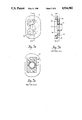
- FIGS. 3a-3c show three views, some in section, of an earpad assembly comprising a preferred embodiment of the invention.
- FIG. 4 is a graph similar to FIG. 2 but showing the benefit of the invention.
- FIGS. 5a-5c show three views, some in section, of a second preferred embodiment of the invention.
- FIGS. 6a-6d show 4 views, some in section, of a third preferred embodiment of the invention.
- FIG. 7 is a cross section of a circumaural hearing protection device comprising two sound sources an orifice, and an earphone in yet another preferred embodiment of the invention.
- FIG. 8 is a cross section of a circumaural ear enclosure comprising an earphone assembly and another preferred embodiment of the invention.
- FIG. 1 wherein there is shown a sectional view of a conventional earmuff cup assembly with a nonlinear bypass assembly according to some of the teachings of U.S. Pat. No. 4,441,576.
- the assembly is cut horizontally across its center as it is worn and viewed from below.
- a typical hard shell 1 covers the ear 2 and rests on a cushion 3 that presses against the head 4 to provide an acoustic seal, restricting the entrance of sound into the large cavity 5.
- Said shell has a nonlinear bypass comprising a cartridge 6 sealed into said shell and comprising an orifice plate 7 with at least one orifice 7a that admits sound from outside to pass through said cartridge thereby serving as a source of sound radiation into a passageway of small volume, referred to generally as 11, enclosed by an earpad assembly (comprising a duct 8, flange 9, and earpad cushion 10) and the concha 12, ear canal 13 and eardrum 14 of the user, said duct being acoustically sealed to said shell around said cartridge at one end and to said flange at the other end.
- the external portion of the ear 2 comprising the pinna 2' and the tragus 15, has an irregular shape that differs widely from one person to another and generally has at least one valley 16, so deep and narrow that even a very soft and compliant earpad cushion 10 cannot conform to its contour without excessive pressure against the ear, there usually occurs some one (or more) leakage opening(s) 17 through which sound may communicate from the said passageway of small volume 11 to the large volume of cavity 5 inside the earcup shell 1, but outside the confines of passageway 11.
- the leakage opening 17 varies in size from one person to another and from one positioning to another on the same person, causing a large variation in the sound pressure level (SPL) measured at the eardrum.
- SPL sound pressure level
- IL measured insertion loss
- FIG. 2 shows a graph of such IL measurements made with a suitable acoustic test fixture (ATF), often referred to as an artificial head, with a microphone at the eardrum position.
- ATF acoustic test fixture
- FIG. 2 shows a graph of such IL measurements made with a suitable acoustic test fixture (ATF), often referred to as an artificial head, with a microphone at the eardrum position.
- ATF acoustic test fixture
- the total open area of the acoustic leakage path can be between 0.5 and 2 cm 2 .
- the total open area of said leakage holes 18 was approximately 1.25 cm 2 , which was approximately equal to the open area of the largest leakage opening 17 commonly encountered between the surface of the earpad cushion 10 and the external surface of a real ear, the variation in IL was reduced to only a few dB, but the insertion loss spectrum closely resembled that of curve B in FIG. 2, which was far from the flat spectrum desired.
- IL in the frequency range near 500 Hz was found to be due to an acoustic interaction between the small volume of the passageway 11 and the large volume of cavity 5 of FIG. 1. Said interaction was satisfactorily controlled by adhering a suitable layer of acoustical foam 19 to the back side of flange 9 so as to form a continuous bond around the edges of leakage holes 18.
- the leakage holes 18 had a total area of approximately 1.25 cm 2 and a total acoustic resistance with acoustically resistive material of between 3 ⁇ 10 5 and 4 ⁇ 10 5 SI acoustic ohms, N sec/m 5 (measured as the linear component of dc flow resistance, i.e., the value obtained from the measured values of flow resistance, over a range of flow speeds, regressed to the limiting value at zero flow speed).
- the frequency of the predominant interaction i.e., the resonance frequency
- the frequency of the predominant interaction i.e., the resonance frequency
- the magnitude of this resonance and its variation resulting from uncontrollable leakage between the earpad and the pinna can be controlled by the magnitude of the effective acoustic resistance supplied by the layer of acoustic foam 19 that is bonded to the back side of flange 9.
- FIGS. 5a-5c illustrating a second preferred embodiment of an earpad designed in accordance with the invention
- a plurality of leakage holes 18a in two groups on opposite sides of the duct opening 8' penetrate through the flange 9a, which is molded with an open cup 20 on its back side surrounding each group of openings 18a, to receive a tightly fitting, piece of acoustically resistive material 19a such as felt or polyurethane foam designed to provide said prescribed acoustical resistance when locked into position by a snapfitting cap 21 having one or a plurality of openings 22 to form a cage (referred to generally as 23) for the resistive material, thereby confining the communicating sound to pass directly through the acoustical material without the need of any bonding or sealing material thus obtaining a reliable and repeatable acoustic resistance amenable to an automated production process.
- acoustically resistive material 19a such as felt or polyurethane foam
- the duct 8b is shown with two openings 18b in its side wall to allow sound communication between passage 11a and cavity 5, each opening 18b capturing within it a preshaped piece of acoustically resistive material 19b such as felt or polyurethane foam that is compressed against flange 9b as it is confined in said opening so as to assure its stable retention and to provide the prescribed value of total acoustic resistance necessary to control the spectral shape and uniformity of IL as herebefore described.
- acoustically resistive material 19b such as felt or polyurethane foam
- FIG. 7 illustrating an ear enclosure comprising a circumaural cushion 3a and a shell 1a that accommodates a cartridge 6a comprising an orifice 7a that admits a portion of the external incident sound 29 which forms a first source of sound, which passes to pass through the shell 1a of the enclosure and which radiates as an entering sound signal into a passageway of small volume 11b comprising one or a plurality of passages around an electroacoustic signaling device 24, acting as a second source of sound, said passages then converging into a common flexible duct 8c sealed to shell 1a at 31 around said electroacoustic signaling device, and sealed to flange 9c at 32, serving to carry sound 29 from the cartridge 6a and sound 30 from said electroacoustic signaling device 24 directly to the eardrum through an earpad cushion 10a pressed against the ear of the user by a small spring force provided either by said duct itself or by auxiliary spring means (not shown).
- the embodiment of the invention shown here comprises a layer of acoustical resistive material 26 inserted between the flange 9c and the earpad cushion 10a thereby forming at least one acoustic leakage hole 18c which, by proper choice of the structure, shape and size, of the resistive material 26 furnishes also the amount of total acoustic resistance required to control the interactive resonance between said passageway of small volume 11b and cavity 5a inside said shell 1a, but outside said passageway of small volume so as to stabilize the sound level at the eardrum and suitably control the shape of the IL between the sources of sound (2a and 24) and said eardrum.
- FIG. 8 in which there is shown a conventional ear enclosure comprising a rigid massive shell 1b supported on circumaural cushion 3b, enclosing an electroacoustic transducer, comprising the at least one source of sound, here referred to as an earphone 25, attached to an earpad assembly comprising a flange 9d, and an earpad cushion 10b, forming an acoustic passage of small volume 11c that carries at least some of the sound generated by said earphone directly to the eardrum of the user when the earpad cushion 10b is gently pressed against the external ear of the user by a spring means such as 27 acting between shell 1b and flange 9d.
- an electroacoustic transducer comprising the at least one source of sound, here referred to as an earphone 25, attached to an earpad assembly comprising a flange 9d, and an earpad cushion 10b, forming an acoustic passage of small volume 11c that carries at least some of the sound generated by said
- the invention comprises at least one opening 18d-e through the earpad assembly, in which is located a prescribed amount of acoustically resistive material 26a to control and reduce the variation in sound level at the eardrum that is otherwise created by uncontrollable sound leakage through opening 17 between the surface of said earpad cushion 10b and the surface of the external ear of the user.
Abstract
Description
Claims (11)
Priority Applications (1)
| Application Number | Priority Date | Filing Date | Title |
|---|---|---|---|
| US07/047,790 US4924502A (en) | 1987-05-08 | 1987-05-08 | Means for stabilizing sound pressure produced at the eardrum under an earpad |
Applications Claiming Priority (1)
| Application Number | Priority Date | Filing Date | Title |
|---|---|---|---|
| US07/047,790 US4924502A (en) | 1987-05-08 | 1987-05-08 | Means for stabilizing sound pressure produced at the eardrum under an earpad |
Publications (1)
| Publication Number | Publication Date |
|---|---|
| US4924502A true US4924502A (en) | 1990-05-08 |
Family
ID=21950992
Family Applications (1)
| Application Number | Title | Priority Date | Filing Date |
|---|---|---|---|
| US07/047,790 Expired - Lifetime US4924502A (en) | 1987-05-08 | 1987-05-08 | Means for stabilizing sound pressure produced at the eardrum under an earpad |
Country Status (1)
| Country | Link |
|---|---|
| US (1) | US4924502A (en) |
Cited By (20)
| Publication number | Priority date | Publication date | Assignee | Title |
|---|---|---|---|---|
| EP0589623A2 (en) * | 1992-09-25 | 1994-03-30 | Sony Corporation | Headphone |
| EP0618751A1 (en) * | 1993-04-02 | 1994-10-05 | CEOTRONICS GmbH ELEKTRONISCHE HÖR- UND SPRECHSYSTEME | Contact microphone for safety helmets and the like |
| US5545859A (en) * | 1994-03-07 | 1996-08-13 | Ullrich; Kenneth A. | Anti-viral acoustically transparent earphone cover |
| US6748087B1 (en) * | 1995-09-07 | 2004-06-08 | Nct Group, Inc. | Headset with ear cushion and means for limiting the compression of the cushion |
| WO2004091253A1 (en) * | 2003-04-09 | 2004-10-21 | Mm Gear Co. Ltd. | Sound wave opening and shutting type case of headphone |
| WO2004091252A1 (en) * | 2003-04-09 | 2004-10-21 | Mm Gear Co. Ltd. | Back sound reduction type headphone |
| US20080123884A1 (en) * | 2006-08-22 | 2008-05-29 | David Donenfeld | Passive hearing aid device |
| US20090041269A1 (en) * | 2007-08-09 | 2009-02-12 | Ceotronics Aktiengesellschaft Audio, Video, Data Communication | Sound transducer for the transmission of audio signals |
| WO2009030231A1 (en) * | 2007-09-07 | 2009-03-12 | Gn Netcom A/S | A headphone comprising an ear cushion, an ear cushion mount comprising a flexible part and a speaker housing as well as a set of headphones and a headset |
| US20090214060A1 (en) * | 2008-02-13 | 2009-08-27 | Neurosky, Inc. | Audio headset with bio-signal sensors |
| US20100232636A1 (en) * | 2009-03-11 | 2010-09-16 | You-Ruei Lin | Headset |
| US20100303270A1 (en) * | 2009-06-01 | 2010-12-02 | Red Tail Hawk Corporation | Ear Defender With Concha Simulator |
| US20100329475A1 (en) * | 2009-06-26 | 2010-12-30 | Mead Killion | Method and apparatus for producing non linear sound attenuation |
| US20110103605A1 (en) * | 2009-10-30 | 2011-05-05 | Etymotic Research, Inc. | Electronic earplug |
| US8651229B2 (en) * | 2012-06-05 | 2014-02-18 | Honeywell International Inc. | Hearing protection |
| US9084053B2 (en) | 2013-01-11 | 2015-07-14 | Red Tail Hawk Corporation | Microphone environmental protection device |
| US20150341733A1 (en) * | 2012-11-22 | 2015-11-26 | Kyocera Corporation | Ear model unit, artificial head, and measurement device and method using said ear model unit and artificial head |
| US9369166B1 (en) * | 2013-05-21 | 2016-06-14 | Larry W. Simnacher | Earpiece attachment for use with a cell phone |
| WO2017169133A1 (en) * | 2016-03-29 | 2017-10-05 | 富士フイルム株式会社 | Earmuff |
| US10911855B2 (en) * | 2018-11-09 | 2021-02-02 | Vzr, Inc. | Headphone acoustic transformer |
Citations (9)
| Publication number | Priority date | Publication date | Assignee | Title |
|---|---|---|---|---|
| US2529562A (en) * | 1947-01-02 | 1950-11-14 | Rca Corp | Adjustable earpiece for receivers |
| US3160717A (en) * | 1962-03-21 | 1964-12-08 | American Optical Corp | Ear protectors |
| US3621488A (en) * | 1970-07-27 | 1971-11-23 | Robert S Gales | Sound attenuating helmet |
| US3862379A (en) * | 1972-07-11 | 1975-01-21 | Akg Akustische Kino Geraete | Headphone construction for interpreter translator arrangements |
| US4071717A (en) * | 1975-04-08 | 1978-01-31 | Akg Akustische U. Kino-Gerate Gesellschaft M.B.H. | Headphone earpiece |
| US4160135A (en) * | 1977-04-15 | 1979-07-03 | Akg Akustische U.Kino-Gerate Gesellschaft M.B.H. | Closed earphone construction |
| US4239945A (en) * | 1976-12-15 | 1980-12-16 | Matsushita Electric Industrial Co., Ltd. | Sealed headphone |
| US4418248A (en) * | 1981-12-11 | 1983-11-29 | Koss Corporation | Dual element headphone |
| US4441576A (en) * | 1982-04-19 | 1984-04-10 | Allen Clayton H | Nonlinear passive acoustic filtering |
-
1987
- 1987-05-08 US US07/047,790 patent/US4924502A/en not_active Expired - Lifetime
Patent Citations (9)
| Publication number | Priority date | Publication date | Assignee | Title |
|---|---|---|---|---|
| US2529562A (en) * | 1947-01-02 | 1950-11-14 | Rca Corp | Adjustable earpiece for receivers |
| US3160717A (en) * | 1962-03-21 | 1964-12-08 | American Optical Corp | Ear protectors |
| US3621488A (en) * | 1970-07-27 | 1971-11-23 | Robert S Gales | Sound attenuating helmet |
| US3862379A (en) * | 1972-07-11 | 1975-01-21 | Akg Akustische Kino Geraete | Headphone construction for interpreter translator arrangements |
| US4071717A (en) * | 1975-04-08 | 1978-01-31 | Akg Akustische U. Kino-Gerate Gesellschaft M.B.H. | Headphone earpiece |
| US4239945A (en) * | 1976-12-15 | 1980-12-16 | Matsushita Electric Industrial Co., Ltd. | Sealed headphone |
| US4160135A (en) * | 1977-04-15 | 1979-07-03 | Akg Akustische U.Kino-Gerate Gesellschaft M.B.H. | Closed earphone construction |
| US4418248A (en) * | 1981-12-11 | 1983-11-29 | Koss Corporation | Dual element headphone |
| US4441576A (en) * | 1982-04-19 | 1984-04-10 | Allen Clayton H | Nonlinear passive acoustic filtering |
Cited By (37)
| Publication number | Priority date | Publication date | Assignee | Title |
|---|---|---|---|---|
| EP0589623A2 (en) * | 1992-09-25 | 1994-03-30 | Sony Corporation | Headphone |
| EP0589623A3 (en) * | 1992-09-25 | 1994-04-13 | Sony Corporation | Headphone |
| US5497427A (en) * | 1992-09-25 | 1996-03-05 | Sony Corporation | Headphone |
| USRE37398E1 (en) * | 1992-09-25 | 2001-10-02 | Sony Corporation | Headphone |
| EP0618751A1 (en) * | 1993-04-02 | 1994-10-05 | CEOTRONICS GmbH ELEKTRONISCHE HÖR- UND SPRECHSYSTEME | Contact microphone for safety helmets and the like |
| US5545859A (en) * | 1994-03-07 | 1996-08-13 | Ullrich; Kenneth A. | Anti-viral acoustically transparent earphone cover |
| US6748087B1 (en) * | 1995-09-07 | 2004-06-08 | Nct Group, Inc. | Headset with ear cushion and means for limiting the compression of the cushion |
| WO2004091253A1 (en) * | 2003-04-09 | 2004-10-21 | Mm Gear Co. Ltd. | Sound wave opening and shutting type case of headphone |
| WO2004091252A1 (en) * | 2003-04-09 | 2004-10-21 | Mm Gear Co. Ltd. | Back sound reduction type headphone |
| US20080123884A1 (en) * | 2006-08-22 | 2008-05-29 | David Donenfeld | Passive hearing aid device |
| US8213643B2 (en) * | 2007-08-09 | 2012-07-03 | Ceotronics Aktiengesellschaft Audio, Video, Data Communication | Sound transducer for the transmission of audio signals |
| US20090041269A1 (en) * | 2007-08-09 | 2009-02-12 | Ceotronics Aktiengesellschaft Audio, Video, Data Communication | Sound transducer for the transmission of audio signals |
| EP2026596A1 (en) * | 2007-08-09 | 2009-02-18 | Ceotronics AG Audio Video Data Communication | Sound transducer for transmitting audio signals |
| WO2009030231A1 (en) * | 2007-09-07 | 2009-03-12 | Gn Netcom A/S | A headphone comprising an ear cushion, an ear cushion mount comprising a flexible part and a speaker housing as well as a set of headphones and a headset |
| US20090214060A1 (en) * | 2008-02-13 | 2009-08-27 | Neurosky, Inc. | Audio headset with bio-signal sensors |
| US8271075B2 (en) * | 2008-02-13 | 2012-09-18 | Neurosky, Inc. | Audio headset with bio-signal sensors |
| US20100232636A1 (en) * | 2009-03-11 | 2010-09-16 | You-Ruei Lin | Headset |
| US8311258B2 (en) * | 2009-03-11 | 2012-11-13 | Cheng Uei Precision Industry Co., Ltd. | Headset |
| US9924261B2 (en) | 2009-06-01 | 2018-03-20 | Red Tail Hawk Corporation | Ear defender with concha simulator |
| US20100303270A1 (en) * | 2009-06-01 | 2010-12-02 | Red Tail Hawk Corporation | Ear Defender With Concha Simulator |
| US8638963B2 (en) * | 2009-06-01 | 2014-01-28 | Red Tail Hawk Corporation | Ear defender with concha simulator |
| US9473846B2 (en) | 2009-06-01 | 2016-10-18 | Red Tail Hawk Corporation | Ear defender with concha simulator |
| US20100329475A1 (en) * | 2009-06-26 | 2010-12-30 | Mead Killion | Method and apparatus for producing non linear sound attenuation |
| US8249285B2 (en) | 2009-06-26 | 2012-08-21 | Etymotic Research Inc. | Method and apparatus for producing non linear sound attenuation |
| US8649540B2 (en) | 2009-10-30 | 2014-02-11 | Etymotic Research, Inc. | Electronic earplug |
| US20110103605A1 (en) * | 2009-10-30 | 2011-05-05 | Etymotic Research, Inc. | Electronic earplug |
| US8651229B2 (en) * | 2012-06-05 | 2014-02-18 | Honeywell International Inc. | Hearing protection |
| US20150341733A1 (en) * | 2012-11-22 | 2015-11-26 | Kyocera Corporation | Ear model unit, artificial head, and measurement device and method using said ear model unit and artificial head |
| US9877125B2 (en) * | 2012-11-22 | 2018-01-23 | Kyocera Corporation | Ear model unit, artificial head, and measurement device and method using said ear model unit and artificial head |
| US9992594B2 (en) | 2012-11-22 | 2018-06-05 | Kyocera Corporation | Ear model unit, artificial head, and measurement device and method using said ear model unit and artificial head |
| US9084053B2 (en) | 2013-01-11 | 2015-07-14 | Red Tail Hawk Corporation | Microphone environmental protection device |
| US9609411B2 (en) | 2013-01-11 | 2017-03-28 | Red Tail Hawk Corporation | Microphone environmental protection device |
| US9369166B1 (en) * | 2013-05-21 | 2016-06-14 | Larry W. Simnacher | Earpiece attachment for use with a cell phone |
| WO2017169133A1 (en) * | 2016-03-29 | 2017-10-05 | 富士フイルム株式会社 | Earmuff |
| CN108778202A (en) * | 2016-03-29 | 2018-11-09 | 富士胶片株式会社 | Earmuff |
| JPWO2017169133A1 (en) * | 2016-03-29 | 2019-01-31 | 富士フイルム株式会社 | Earmuff |
| US10911855B2 (en) * | 2018-11-09 | 2021-02-02 | Vzr, Inc. | Headphone acoustic transformer |
Similar Documents
| Publication | Publication Date | Title |
|---|---|---|
| US4924502A (en) | Means for stabilizing sound pressure produced at the eardrum under an earpad | |
| US4441576A (en) | Nonlinear passive acoustic filtering | |
| US4852683A (en) | Earplug with improved audibility | |
| US5426719A (en) | Ear based hearing protector/communication system | |
| Berger | Methods of measuring the attenuation of hearing protection devices | |
| US6567525B1 (en) | Supra aural active noise reduction headphones | |
| US3968334A (en) | Audiometric method and apparatus for testing the effectiveness of hearing protective devices | |
| WO1994005231A9 (en) | Ear based hearing protector/communication system | |
| US20070237349A1 (en) | Earbud earphone and cushion therefor | |
| US4071717A (en) | Headphone earpiece | |
| US4465159A (en) | Nonlinear ear protecting device | |
| US20120243699A1 (en) | Ear canal transducer mounting system | |
| US8180091B2 (en) | Headphone | |
| US11405717B2 (en) | Pressure equalizing earphone | |
| Frank et al. | Attenuation provided by four different audiometric earphone systems | |
| Villchur | Audiometer‐Earphone Mounting to Improve Intersubject and Cushion‐Fit Reliability | |
| Gerges et al. | Hearing protectors | |
| Zera et al. | Comparison between subjective and objective measures of active hearing protector and communication headset attenuation | |
| Yost et al. | Hearing thresholds | |
| JP2006270964A (en) | Ear bud earphone and cushion for ear bud earphone | |
| Steeneken et al. | Personal active noise reduction with integrated speech communication devices: development and assessment | |
| Carmichel et al. | Effects of binaural electronic hearing protectors on localization and response time to sounds in the horizontal plane | |
| Shaw | Hearing protector attenuation: A perspective view | |
| Agnew | Audible circuit noise in hearing aid amplifiers | |
| US11887577B2 (en) | System and method for evaluating an acoustic characteristic of an electronic device |
Legal Events
| Date | Code | Title | Description |
|---|---|---|---|
| AS | Assignment |
Owner name: CABOT CORPORATION, INDIANA Free format text: ASSIGNMENT OF ASSIGNORS INTEREST;ASSIGNORS:ALLEN, CLAYTON H.;BERGER, ELLIOTT H.;SIGNING DATES FROM 19870611 TO 19870615;REEL/FRAME:004744/0862 Owner name: CABOT CORPORATION, 7911 ZIONSVILLE RD., INDIANAPOL Free format text: ASSIGNMENT OF ASSIGNORS INTEREST.;ASSIGNORS:ALLEN, CLAYTON H.;BERGER, ELLIOTT H.;REEL/FRAME:004744/0862;SIGNING DATES FROM 19870611 TO 19870615 |
|
| STCF | Information on status: patent grant |
Free format text: PATENTED CASE |
|
| AS | Assignment |
Owner name: CABOT SAFETY CORPORATION Free format text: ASSIGNMENT OF ASSIGNORS INTEREST.;ASSIGNOR:CABOT CORPORATION;REEL/FRAME:005951/0108 Effective date: 19911213 |
|
| FPAY | Fee payment |
Year of fee payment: 4 |
|
| FEPP | Fee payment procedure |
Free format text: PAYOR NUMBER ASSIGNED (ORIGINAL EVENT CODE: ASPN); ENTITY STATUS OF PATENT OWNER: LARGE ENTITY |
|
| AS | Assignment |
Owner name: BANKERS TRUST COMPANY, NEW YORK Free format text: SECURITY INTEREST;ASSIGNOR:CABOT SAFETY INTERMEDIATE CORPORATION;REEL/FRAME:007570/0516 Effective date: 19950711 |
|
| AS | Assignment |
Owner name: CABOT SAFETY INTERMEDIATE CORPORATION, MASSACHUSET Free format text: ASSIGNMENT OF ASSIGNORS INTEREST;ASSIGNOR:CABOT SAFETY CORPORATION;REEL/FRAME:007570/0220 Effective date: 19950711 |
|
| FEPP | Fee payment procedure |
Free format text: PAYER NUMBER DE-ASSIGNED (ORIGINAL EVENT CODE: RMPN); ENTITY STATUS OF PATENT OWNER: LARGE ENTITY |
|
| FPAY | Fee payment |
Year of fee payment: 8 |
|
| SULP | Surcharge for late payment | ||
| FPAY | Fee payment |
Year of fee payment: 12 |
|
| REMI | Maintenance fee reminder mailed | ||
| AS | Assignment |
Owner name: DEUTSCHE BANK AG, NEW YORK BRANCH, NEW YORK Free format text: SECURITY AGREEMENT;ASSIGNOR:CABOT SAFETY INTERMEDIATE CORPORATION;REEL/FRAME:015293/0386 Effective date: 20040420 Owner name: CABOT SAFETY INTERMEDIATE CORPORATION, DELAWARE Free format text: ASSIGNMENT OF ASSIGNORS INTEREST;ASSIGNOR:DEUTSCHE BANK TRUST COMPANY AMERICAS (F.K.A. BANKERS TRUST COMPANY);REEL/FRAME:015293/0406 Effective date: 20040420 Owner name: DEUTSCHE BANK AG, NEW YORK BRANCH,NEW YORK Free format text: SECURITY AGREEMENT;ASSIGNOR:CABOT SAFETY INTERMEDIATE CORPORATION;REEL/FRAME:015293/0386 Effective date: 20040420 |
|
| AS | Assignment |
Owner name: CABOT SAFETY INTERMEDIATE CORPORATION,NORTH CAROLI Free format text: RELEASE OF SECURITY INTEREST;ASSIGNOR:DEUTSCHE BANK AG, NEW YORK BRANCH;REEL/FRAME:017626/0347 Effective date: 20060324 Owner name: CABOT SAFETY INTERMEDIATE CORPORATION, NORTH CAROL Free format text: RELEASE OF SECURITY INTEREST;ASSIGNOR:DEUTSCHE BANK AG, NEW YORK BRANCH;REEL/FRAME:017626/0347 Effective date: 20060324 |
|
| AS | Assignment |
Owner name: BANK OF AMERICA, N.A., AS FIRST LIEN COLLATERAL AG Free format text: SECURITY AGREEMENT;ASSIGNOR:CABOT SAFETY INTERMEDIATE CORPORATION;REEL/FRAME:017435/0721 Effective date: 20060324 Owner name: BANK OF AMERICA, N.A., AS SECOND LIEN COLLATERAL A Free format text: SECURITY AGREEMENT;ASSIGNOR:CABOT SAFETY INTERMEDIATE CORPORATION;REEL/FRAME:017435/0764 Effective date: 20060324 |
|
| AS | Assignment |
Owner name: CABOT SAFETY INTERMEDIATE CORPORATION,NORTH CAROLI Free format text: RELEASE OF SECURITY INTEREST;ASSIGNOR:DEUTSCHE BANK AG, NEW YORK BRANCH;REEL/FRAME:017663/0508 Effective date: 20060324 Owner name: CABOT SAFETY INTERMEDIATE CORPORATION, NORTH CAROL Free format text: RELEASE OF SECURITY INTEREST;ASSIGNOR:DEUTSCHE BANK AG, NEW YORK BRANCH;REEL/FRAME:017663/0508 Effective date: 20060324 |
|
| AS | Assignment |
Owner name: CABOT SAFETY INTERMEDIATE CORPORATION, DELAWARE Free format text: RELEASE OF FIRST LIEN SECURITY INTEREST AT REEL/FRAME NO. 17435/0721;ASSIGNOR:BANK OF AMERICA, N.A., AS FIRST LIEN COLLATERAL AGENT;REEL/FRAME:019511/0914 Effective date: 20070601 Owner name: CABOT SAFETY INTERMEDIATE CORPORATION,DELAWARE Free format text: RELEASE OF FIRST LIEN SECURITY INTEREST AT REEL/FRAME NO. 17435/0721;ASSIGNOR:BANK OF AMERICA, N.A., AS FIRST LIEN COLLATERAL AGENT;REEL/FRAME:019511/0914 Effective date: 20070601 |
|
| AS | Assignment |
Owner name: CABOT SAFETY INTERMEDIATE CORPORATION, DELAWARE Free format text: RELEASE OF SECOND LIEN SECURITY INTEREST AT REEL/FRAME NO. 17435/0764;ASSIGNOR:BANK OF AMERICA, N.A.;REEL/FRAME:020733/0510 Effective date: 20080401 Owner name: CABOT SAFETY INTERMEDIATE CORPORATION,DELAWARE Free format text: RELEASE OF SECOND LIEN SECURITY INTEREST AT REEL/FRAME NO. 17435/0764;ASSIGNOR:BANK OF AMERICA, N.A.;REEL/FRAME:020733/0510 Effective date: 20080401 |