US4923449A - Apparatus for collecting constant amounts of blood from individual donors - Google Patents
Apparatus for collecting constant amounts of blood from individual donors Download PDFInfo
- Publication number
- US4923449A US4923449A US07/122,025 US12202587A US4923449A US 4923449 A US4923449 A US 4923449A US 12202587 A US12202587 A US 12202587A US 4923449 A US4923449 A US 4923449A
- Authority
- US
- United States
- Prior art keywords
- blood
- weighing platform
- bag
- collection
- load cell
- Prior art date
- Legal status (The legal status is an assumption and is not a legal conclusion. Google has not performed a legal analysis and makes no representation as to the accuracy of the status listed.)
- Expired - Fee Related
Links
- 239000008280 blood Substances 0.000 title claims abstract description 128
- 210000004369 blood Anatomy 0.000 title claims abstract description 128
- 238000005303 weighing Methods 0.000 claims abstract description 81
- 230000010355 oscillation Effects 0.000 claims abstract description 38
- 239000003146 anticoagulant agent Substances 0.000 claims abstract description 14
- 229940127219 anticoagulant drug Drugs 0.000 claims abstract description 14
- 238000000034 method Methods 0.000 claims description 6
- 230000036772 blood pressure Effects 0.000 description 10
- 238000005259 measurement Methods 0.000 description 8
- 239000008279 sol Substances 0.000 description 8
- 239000000463 material Substances 0.000 description 5
- 238000004891 communication Methods 0.000 description 4
- 230000005484 gravity Effects 0.000 description 4
- 238000005192 partition Methods 0.000 description 4
- 230000006835 compression Effects 0.000 description 3
- 238000007906 compression Methods 0.000 description 3
- 230000000994 depressogenic effect Effects 0.000 description 2
- 238000013461 design Methods 0.000 description 2
- 238000010586 diagram Methods 0.000 description 2
- 238000001990 intravenous administration Methods 0.000 description 2
- 229920000915 polyvinyl chloride Polymers 0.000 description 2
- 239000004800 polyvinyl chloride Substances 0.000 description 2
- 239000004925 Acrylic resin Substances 0.000 description 1
- 229920000178 Acrylic resin Polymers 0.000 description 1
- 206010053567 Coagulopathies Diseases 0.000 description 1
- 230000001133 acceleration Effects 0.000 description 1
- 230000017531 blood circulation Effects 0.000 description 1
- 239000012503 blood component Substances 0.000 description 1
- 210000004204 blood vessel Anatomy 0.000 description 1
- 230000035602 clotting Effects 0.000 description 1
- 238000012790 confirmation Methods 0.000 description 1
- 238000010276 construction Methods 0.000 description 1
- 238000007796 conventional method Methods 0.000 description 1
- 239000003814 drug Substances 0.000 description 1
- 238000002474 experimental method Methods 0.000 description 1
- 239000012530 fluid Substances 0.000 description 1
- 238000007689 inspection Methods 0.000 description 1
- 238000004519 manufacturing process Methods 0.000 description 1
- 230000003534 oscillatory effect Effects 0.000 description 1
- 229920003023 plastic Polymers 0.000 description 1
- 239000004033 plastic Substances 0.000 description 1
- 239000002985 plastic film Substances 0.000 description 1
- 238000012545 processing Methods 0.000 description 1
- 230000000717 retained effect Effects 0.000 description 1
- 229940124597 therapeutic agent Drugs 0.000 description 1
- 238000002560 therapeutic procedure Methods 0.000 description 1
- -1 typically Substances 0.000 description 1
- 230000000007 visual effect Effects 0.000 description 1
Images


Classifications
-
- A—HUMAN NECESSITIES
- A61—MEDICAL OR VETERINARY SCIENCE; HYGIENE
- A61M—DEVICES FOR INTRODUCING MEDIA INTO, OR ONTO, THE BODY; DEVICES FOR TRANSDUCING BODY MEDIA OR FOR TAKING MEDIA FROM THE BODY; DEVICES FOR PRODUCING OR ENDING SLEEP OR STUPOR
- A61M1/00—Suction or pumping devices for medical purposes; Devices for carrying-off, for treatment of, or for carrying-over, body-liquids; Drainage systems
- A61M1/02—Blood transfusion apparatus
- A61M1/024—Means for controlling the quantity of transfused blood, e.g. by weighing the container and automatic stopping of the transfusion after reaching a determined amount
- A61M1/0245—Means for controlling the quantity of transfused blood, e.g. by weighing the container and automatic stopping of the transfusion after reaching a determined amount combined with blood container shaking means
-
- A—HUMAN NECESSITIES
- A61—MEDICAL OR VETERINARY SCIENCE; HYGIENE
- A61M—DEVICES FOR INTRODUCING MEDIA INTO, OR ONTO, THE BODY; DEVICES FOR TRANSDUCING BODY MEDIA OR FOR TAKING MEDIA FROM THE BODY; DEVICES FOR PRODUCING OR ENDING SLEEP OR STUPOR
- A61M1/00—Suction or pumping devices for medical purposes; Devices for carrying-off, for treatment of, or for carrying-over, body-liquids; Drainage systems
- A61M1/60—Containers for suction drainage, adapted to be used with an external suction source
- A61M1/62—Containers comprising a bag in a rigid low-pressure chamber, with suction applied to the outside surface of the bag
-
- Y—GENERAL TAGGING OF NEW TECHNOLOGICAL DEVELOPMENTS; GENERAL TAGGING OF CROSS-SECTIONAL TECHNOLOGIES SPANNING OVER SEVERAL SECTIONS OF THE IPC; TECHNICAL SUBJECTS COVERED BY FORMER USPC CROSS-REFERENCE ART COLLECTIONS [XRACs] AND DIGESTS
- Y10—TECHNICAL SUBJECTS COVERED BY FORMER USPC
- Y10S—TECHNICAL SUBJECTS COVERED BY FORMER USPC CROSS-REFERENCE ART COLLECTIONS [XRACs] AND DIGESTS
- Y10S604/00—Surgery
- Y10S604/903—Medical container with material agitation means
Definitions
- This invention relates to apparatus for collection of blood as a therapeutic agent, and more specifically to such apparatus featuring provisions for collection of prescribed amounts of blood from individual donors with little or no human assistance.
- the apparatus in accordance with the invention lends itself to use at blood banks, hospitals, blood donation cars, and any other institutions or agencies where blood is donated for transfusion and other purposes.
- Efficient collection of blood from as many donors as possible is a key factor for the extensive practice of transfusions and related methods of therapy at numerous medical organizations existing today.
- the usual practice for blood collection involves the use of a disposable bag, fabricated from polyvinyl chloride in sheet form, for each single donor.
- the bag has a pipe of pliant material extending therefrom and terminating in an intravenous needle.
- An adequate amount of anticoagulant is previously introduced into the bag in order to prevent the clotting of the collected blood.
- the needle In the use of the collection bag the needle is thrusted into a vessel of the donor, with the result that the blood flows through the pipe into the bag by virtue of the blood pressure of the donor himself.
- the donor Before the collection the donor can choose the amount of blood he will donate at one time from between 200 cubic centimeters (cc) and 400 cc, although, of course, these values may vary from country to country.
- cc cubic centimeters
- 400 cc cc
- a collection bag having a capacity matching each donor's choice is used for collection. In the applicant's country, law permits collection errors up to+10 percent of the amount chosen by the donor, there being no regulation against shortages.
- the shaking of the bag requires the oscillation, rather than rectilinear reciprocation, of the platform on which the bag is mounted during collection.
- the accurate weighing of the collected blood on the pivoted oscillatory platform demands additional considerations that must go into the design of the apparatus.
- the present invention ovecomes the listed weaknesses of the prior art and provides an improved apparatus capable of efficient, automatic collection of prescribed amounts of blood with a minimum of errors.
- the blood collection apparatus in accordance with the invention is intended for use with a collection bag unit having an inflatable bag to be filled with blood, a collapsible inflow pipe extending from and communicating with the bag for introducing the blood therein, and a needle at the tip of the inflow pipe for blood collection from a donor.
- the apparatus particularly features the use of a load cell coupled to a weighing platform on which the bag is placed during blood collection.
- the load cell puts out an electric weight signal representative of the weight of the blood being collected in the bag.
- the load cell together with the weighing platform is mounted to a swing cradle which is oscillated about a horizontal axis by a shaking mechanism for shaking the bag on the weighing platform.
- a control means Responsive to the weight signal from the load cell is a control means which puts out a collection stop signal when a preselected amount of blood is collected in the bag.
- the collection stop signal is applied to a collection stop mechanism for causing the same to terminate the blood collection by collapsing the inflow pipe of the bag unit.
- the blood can be introduced via the inflow tube into the bag solely by virtue of the donor's blood pressure.
- the weighing platform may be disposed in a vacuum chamber, so that the blood may be fed by the differential between the blood pressure and the negative pressure created in the vacuum chamber.
- the increasing weight of the blood in the bag is measured piezoelectrically by the load cell and is thereby converted into the electric weight signal.
- the specific gravity of each donor's blood is measured prior to collection, and the blood is collected only when the specific gravity is found to fall within a prescribed range. It is therefore possible to collect a predetermined amount of blood within the noted tolerance range through weight measurement.
- the weight signal from the load cell accurately represents the weight of the blood that has been collected, so that the blood collection can be terminated by the collection stop mechanism just when the preselected amount of blood is collected. If the bag has been placed in the evacuated chamber, this chamber may also be placed in communication with the atmosphere upon completion of the blood collection.
- the amount of blood being collected is measured piezoelectrically in accordance with the invention, instead of by a spring balance or equivalent weighing machines as in the prior art.
- a particular advantage accruing from the use of the load cell is that it is far less affected than other types of weighing machines by the shaking of the bag during blood collection. This advantage becomes all the more pronounced because the shaking of the bag is unavoidable for intimately intermingling the collected blood and the anticoagulant that has been previously introduced into the bag.
- FIG. 1 is a perspective view of the blood collection apparatus constructed in accordance with the novel concepts of the invention
- FIG. 2 is an enlarged fragmentary vertical section through the apparatus of FIG. 1, showing in particular the weighing platform, load cell, swing cradle, and bag shaking mechanism;
- FIG. 3 is an enlarged side elevation of the collection stop mechanism included in the apparatus of FIG. 1;
- FIG. 4 is an enlarged perspective view of a support plate supporting a horizontal pivot pin about which the swing cradle of FIG. 2 oscillates;
- FIG. 5 is an enlarged perspective view of the swing cradle
- FIG. 6 is an illustration of a collection bag unit for use with the apparatus of FIG. 1;
- FIG. 7 is a block diagram of the electric control system incorporated with the apparatus of FIG. 1;
- FIG. 8 is an elevation of the apparatus of FIG. 1, partly shown broken away to reveal those parts which are not shown in FIG. 2;
- FIG. 9 is a graph plotting the output voltage of the load cell against time, the graph being explanatory of the way in which the shaking or oscillation of the weighing platform is terminated when it gains a horizontal attitude prior to blood collection;
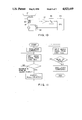
- FIG. 10 is a block diagram of the electrical control system for use in obtaining the horizontal attitude of the weighing platform at the start of blood collection;
- FIG. 11 is a flow chart explanatory of the operation of the control system of FIG. 10;
- FIG. 12 is a diagrammatic illustration of an alternative system for obtaining the horizontal attitude of the weighing platform at the start of blood collection.
- FIG. 13 is a flow chart explanatory of the operation of the system of FIG. 12.
- the blood collection apparatus in accordance with the invention includes a generally boxlike, open-top enclosure 5 having a hinged lid 22 of rigid plastic material, preferably acrylic resin, for openably closing the top of the enclosure.
- a hinged lid 22 of rigid plastic material preferably acrylic resin
- the vacuum chamber 6 accommodates a weighing platform 21 as well as a collection bag unit 1 placed thereon.
- the partition 50 is centrally depressed at 7 to provide a space, in open communication with the vacuum chamber 6, for receiving a load cell L coupled to the weighing platform 21 and means for shaking the platform during blood collection, as will be detailed presently.
- the collection bag unit 1 can be of the conventional design comprising an inflatable bag 2 of pliant plastic sheet material such as, typically, polyvinyl chloride.
- a collapsible blood inflow pipe 3 which can be of the same material as the bag 2, extends therefrom and has an intravenous needle 4 attached to its tip.
- the bag 2 contains a suitable amount of anticoagulant introduced therein preparatory to use.
- One such collection bag unit 1 is used for each donor.
- the illustrated collection bag unit 1 may be additionally provided with a supplementary bag or bags 2a which can be placed in and out of communication with the primary bag 2.
- the supplementary bag or bags are for use in separating the whole blood that has been collected in the primary bag 2, into such useful blood components as red corpuscles, plasma, white corpuscles, platelets, cryoprecipitates, etc. Up to three such supplementary bags may be combined with the primary bag 2 via suitable flexible piping to make up one collection bag unit.
- the primary and supplementary bags may be stacked up on the weighing platform 21 during blood collection.
- an upstanding support plate 9 is secured to a fixed mounting lug 10 which is bottomed against the depression 7 in the partition 50.
- a horizontal pivot pin 8 is cantilevered to the support plate 9 for supporting a swing cradle 11.
- the load cell L is rigidly mounted on the swing cradle 11 for joint oscillation therewith about the horizontal pivot pin 8.
- FIG. 5 is a detailed illustration of the swing cradle 11 on an enlarged scale. It comprises an elongate major portion 14 generally extending substantially horizontally, and a pair of upstanding lugs 12 secured to the opposite sides of the major portion and extending upwardly therefrom. A pair of aligned holes 13 are defined in the lugs 12 for rotatably receiving the pivot pin 8, so that the swing cradle 11 can oscillate about this pivot.
- the major portion 14 has a raised seat 15 formed adjacent one end thereof.
- FIG. 2 A reconsideration of FIG. 2 will reveal that the load cell L is mounted fast to the swing cradle 11 by having a proximal end portion thereof fastened to the raised seat 15 by screws, not shown, which are inserted into and through clearance holes 16 from the cradle underside. Extending from a distal end of the load cell L, an upstanding rod 51 is coupled to the weighing platform 21.
- a bag shaking mechanism 53 For oscillating the swing cradle 11 and hence for shaking the bag 2 of the collection bag unit 1 on the weighing platform 21 during blood collection, there is provided a bag shaking mechanism 53, FIG. 2, which acts directly on the swing cradle. It will be noted from both FIGS. 2 and 5 that one of the lugs 12 of the swing cradle 11 has a pair of cam follower arms 18 depending therefrom in parallel spaced relation to each other.
- the bag shaking mechanism 53 includes an eccentric cam 20 somewhat loosely engaged between the pair of cam follower arms 18.
- the eccentric cam 20 is eccentrically and rigidly mounted on the armature shaft 19 of an electric drive motor which is not seen in FIG. 2 but which is to appear in subsequent figures of the drawing attached hereto.
- the drive motor is mounted fast to the support plate 9, with the armature shaft 19 extending with clearance through a hole 9a, FIG. 4, in the support plate.
- the eccentrically revolving cam 20 will act on the pair of cam follower arms 18 thereby causing the swing cradle 11 to swing about the pivot pin 8 and so shaking the bag 2 on the weighing platform 21.
- the vacuum chamber 6 as well as the space bounded by the depression 7 in the partition 50 communicates via a conduit 17 with a vacuum pump P on the bottom of the enclosure 5.
- An adjustable throttle valve may be provided between vacuum chamber 6 and vacuum pump P for controlling the degree of vacuum in the vacuum chamber.
- the vacuum chamber 6 can be evacuated by the vacuum pump P for drawing the blood from the donor into the bag 2 on the weighing platform 21.
- the evacuation of the chamber 6 is no essential feature of the invention, since blood can be collected as aforesaid solely by the blood pressure of the donor.
- Seen at 23 in FIG. 1 is a recess formed in the lid 22 to permit the inflow pipe 3 of the bag unit 1 to extend outwardly therethrough when the lid is closed.
- the load cell L puts out an electric voltage signal proportional to the applied pressure, which in this case is the weight of the collected blood within the bag 2 on the weighing platform 21.
- the load cell L is electrically connected to a controller CT, shown both in FIGS. 7 and 8, for delivering thereto the electric weight signal representative of the weight of the collected blood.
- the controller CT is connected in turn to both the vacuum pump P and a solenoid SOL forming a part of a collection stop mechanism to be set forth subsequently.
- the controller CT Inputting the weight signal from the load cell L, the controller CT ascertains the weight of the blood being collected in the bag 2 and puts out a collection stop signal for setting the vacuum pump P out of operation, and for energizing the solenoid SOL, when a preselected amount of blood is collected. Upon energization of the solenoid the collection stop mechanism will operate to terminate blood inflow into the bag 2 by collapsing the inflow pipe 3 at a point intermediate its opposite ends.
- FIG. 1 shows some parts of the collection stop mechanism, as generally indicated by the numeral 52
- FIG. 3 better reveals its construction including the solenoid SOL.
- the collection stop mechanism 52 further comprises a fixed gripping jaw 24 and a movable gripping jaw 25, which are arranged to engage therebetween the blood inflow pipe 3 of the bag unit 1 as it extends out of the enclosure 5 through the recess 23 in the lid 22. Pivoted at 26 on the enclosure 5, the movable gripping jaw 25 is movable toward and away from the fixed gripping jaw 24.
- a helical tension spring 30 biases the movable gripping jaw 25 toward the fixed gripping jaw 24.
- a hand lever 27 Rigidly coupled to the movable gripping jaw 25 and extending at right angles therewith is a hand lever 27 having its right hand end, as viewed in FIG. 3, extending outwardly from within the enclosure 5.
- the left hand end of the hand lever 27 is arranged for operative engagement with a locking lever 29 which is medially pivoted at 28 on the enclosure 5.
- One end of the locking lever 29 is coupled to the plunger of the solenoid SOL.
- a helical compression spring 31 sleeved upon its plunger holds the locking lever 29 in the position depicted by the solid lines in FIG. 3. With the locking lever 29 in this normal position, the hand lever 27 also lines in its solid line position as the movable gripping jaw 25 is urged against the fixed gripping jaw 24 by the force of the tension spring 30.
- the locking lever 29 has an angled slideway 29a and abutment 29b formed on its edge facing the hand lever 27.
- the hand lever 27 When the hand lever 27 is manually turned clockwise, as seen in FIG. 3, against the force of the tension spring 30, the left hand end of the hand lever will slide on the slideway 29a, turning the locking lever 29 counterclockwise against the force of the compression spring 31 in so doing, and will come to ride on the abutment 29b.
- the movable gripping jaw 25 is locked in its position away from the fixed gripping jaw 24.
- the locking lever 29 Upon subsequent energization of the solenoid SOL, the locking lever 29 will unlock the hand lever 27 thereby permitting the movable gripping jaw 25 to pivot toward the fixed gripping jaw 24 under the bias of the tension spring 30.
- Seen at 32 in FIG. 1 is a switch button on a control panel 53 on the front face of the enclosure 5 for presetting the electric circuitry of the apparatus for either 200 cc or 400 cc blood collection.
- a control panel 53 is disposed on the control panel 53 .
- the LEDs 53 will glow one after another when every 20% of the preselected amount of blood is collected, so that all the LEDs will glow upon completion of the blood collection.
- a vacuum control knob 34 is disposed on the right hand side, as seen in FIG. 1, of the enclosure 5 for manually controlling the unshown throttle valve between vacuum chamber 6 and vacuum pump P. Observing a pressure gage 35 on the control panel 53, the operator may turn the knob 34 to control the degree of vacuum established in the vacuum chamber 6 and, in consequence, the rate of blood collection from each donor.
- the bag 2 of an unused collection bag unit 1 is placed on the weighing platform 21, as indicated by the phantom outline in FIG. 2, after opening the lid 22.
- the inflow pipe 3 of the bag unit 1 is threaded between the pair of gripping jaws 24 and 25 of the collection stop mechanism 52. It is understood that the exposed right hand tip, as seen in FIGS. 1 and 3, of the hand lever 27 has been depressed against the force of the tension spring 50. As the left hand tip of the hand lever rides on the abutment 29b of the locking lever 29, the movable gripping jaw 25 is retained away from the fixed gripping jaw 24, so that the inflow pipe 3 can pass uncollapsed between these jaws.
- the needle 4 at the tip of the inflow pipe 3 may now be inserted in a blood vessel of the donor.
- the blood will flow from the donor into the bag 1 solely under his own blood pressure.
- the vacuum chamber 6 may be evacuated, provided that the donor has been found to be capable of withstanding such rapid donation.
- the lid 22 may be closed, and the vacuum pump P may be set into operation. Atmospheric air will be admitted into the vacuum chamber 6 only at a minimal rate as the inflow pipe 3 extends outwardly from the vacuum chamber 6 through the recess 23 in the bottom edge of the lid 22.
- the blood Upon evacuation of the vacuum chamber 6 the blood will be drawn into the bag 2 by the differential between the negative pressure of that chamber and the donor's blood pressure. The resulting rate of collection will be higher than in the case where the blood is fed only by the blood pressure.
- the drive motor of the bag shaking mechanism 53 may be maintained in constant rotation.
- the eccentric cam 20 on the armature shaft of the motor will act on the pair of cam follower arms 18 of the swing cradle 11 thereby causing the latter to oscillate about the horizontal pivot 8 together with the load cell L, weighing platform 21 and bag 2.
- the anticoagulant that has been present therein will intimately mingle with the incoming blood for maintaining its fluid state.
- the load cell L Strained by the increasing weight of the blood within the bag 2, the load cell L will constantly deliver to the controller CT the weight signal representative of the weight of the collected blood. It has been stated that the specific gravity of each donor's blood is measured prior to collection, and the blood is collected only when its specific gravity is found to fall within a prescribed range. It is therefore possible to collect a prescribed amount of blood within the noted tolerance range through the measurement of weight instead of capacity.
- the bag 2, weighing platform 21 and load cell L are all in constant angular diplacement during blood collection. Not only the angular position, but also the varying degrees of acceleration, of these members affect the measurement of the blood weight by the load cell. The resulting difference between the actual weight of the collected blood and the measurement of the load cell will be negligible, being normally up to three percent or so.
- the weight signal produced by the load cell L may be sampled periodically (e.g. every 12/1000 second), and the weight may be ascertained from these samples, at the controller CT.
- the weight signal may be sampled when the load cell L is in the same angular position, as will be later explained in more detail.
- Each cycle of oscillation of the swing cradle 11 is typically from two to three seconds, much shorter than the time required for blood collection from one donor. Therefore, such intermittent measurement will enable collection with a practically acceptable degree of accuracy.
- the controller CT may be adapted for audio-announcement of the progress and completion of collection.
- FIG. 8 shows at S the means for the production of such audio-announcements.
- the controller CT When a preselected amount (e.g. 200 cc or 400 cc) of blood is collected, the controller CT will produce, in response to the weight signal from the load cell L, the collections top signal for causing the energization of the solenoid SOL of the collection stop mechanism 52.
- the solenoid SOL on energization will turn the locking lever 29 counterclockwise, as seen in FIG. 3, against the force of the compression spring 31.
- the movable gripping jaw 25 will pivot counterclockwise with the hand lever under the force of the tension spring 30 thereby gripping and so collapsing the inflow pipe 3 of the collection bag unit 1 between itself and the fixed gripping jaw 24.
- the vacuum pump P if it has been in operation, may also be set out of operation at the same time with the energization of the solenoid SOL. Further the vacuum chamber 6 may be placed in communication with the atmosphere as by opening an unshown solenoid valve.
- the sum of the weight of the weighing platform 21 and that of the bag unit 1 must be deducted from the gross weight exerted on the load cell L in order to obtain the net weight of the blood.
- the weight of the platform 21 is constant, so that its value may be previously input to the controller CT.
- the weight or so-called "tare" of the bag unit 1 is variable, depending upon its capacity and material and the amount of the anticoagulant prefilled therein, so that each bag unit must be weighed preparatory to the start of blood collection.
- FIG. 10 block diagrammatically illustrates an example of means herein employed for automatic readjustment of the angular position of the load cell L as well as the weighing platform 21 in order to make them horizontal before taring each new bag unit.
- the load cell L is electrically coupled to a microprocessor or central processing unit (CPU) 39 via an operational amplifier 37 and analog-to-digital (A/D) converter 38.
- the CPU 39 has an output coupled to an on-off switch such as a solid-state relay CR connected in an alternating current supply circuit for the drive motor M which oscillates the load cell L via the eccentric cam 20.
- an on-off switch such as a solid-state relay CR connected in an alternating current supply circuit for the drive motor M which oscillates the load cell L via the eccentric cam 20.
- the CPU 39 is so programmed that, as the blood collection apparatus is electrically turned on, the switch CR is immediately closed to set the drive motor M into operation and hence to start oscillation of the weighing platform 21, with no bag unit loaded thereon.
- the load cell L will then put out the weight signal representative of the weight of the unloaded platform 21, which weight will vary with the oscillation of the platform and load cell.
- the microprocessor 39 is programmed to ascertain the maximum value M and minimum value m of the weight signal and further to compute the difference (M-m) therebetween.
- the output voltage (weight signal) of the load cell L will vary cyclically between the maximum M and minimum m with the oscillation of the unloaded platform 21.
- the CPU 39 computes the difference between the maximum M and minimum m magnitudes of the weight signal incoming during at least one, preferably three, cycles of the weight signal. Then the CPU proceeds to compute the magnitude Mstop of the weight signal at which the oscillation of the weighing platform 21 is to be terminated, in accordance with the formula:
- C is a constant in the range of about 0.85-0.95, preferably about 0.90.
- the drive motor M is to be set out of rotation when the magnitude of the subsequently incoming weight signal becomes slightly less than the previously ascertained maximum value M.
- the oscillation of the unloaded platform 21 is continued after the initial three cycles of the weight signal during which its maximum and minimum values have been obtained.
- the magnitude of the weight signal increases and reaches the prescribed magnitude Mstop as at C in FIG. 9, the CPU will put out a signal for opening the on-off switch CR thereby terminating the oscillation of the unloaded platform 21.
- the drive motor M is set out of rotation not at the exact moment the weighing platform 21 gains the horizontal attitude but shortly before that moment. This is because the platform remains in motion by inertia for a brief period after the drive motor has been de-energized. It is therefore essential that the drive motor be set out of rotation while the weight signal from the load cell L is increasing in magnitude, that is, while the weighing platform is swinging toward, rather than away from, the horizontal position.
- FIG. 9 An inspection of FIG. 9 will show that the loading of the empty bag unit on the horizontal platform 21 results in an increase in the magnitude of the weight signal by Vw. This increase represents the tare to be deducted, at the CPU 39, from the subsequent weighing of the collected blood.
- the drive motor M is again set into rotation following the loading of the empty bag unit 1 on the weighing platform 21, and the blood is collected from the donor in the bag unit, as has been set forth previously.
- the collection can be terminated when the net weight of the collected blood (i.e. the gross weight minus the above obtained tare) reaches a preselected value.
- FIG. 12 is a diagrammatic illustration of another possible arrangement for gaining the horizontal attitude of the weighing platform 21 in order to tare each new bag unit preparatory to blood collection.
- the load cell L with the weighing platform 21 thereon is mounted on a swing cradle 44 capable of oscillation about a horizontal axis.
- the swing cradle 44 is operatively coupled to one end of a link 43.
- the other end of this link is pivotally coupled at 42 to a rotary member such as a disk 41 in an eccentric position thereon.
- the disk 41 is mounted on the armature shaft 40 of a drive motor M for joint rotation therewith.
- the rotation of the drive motor M is translated into the oscillation of the swing cradle 44.
- a photosensor 46 Disposed in a prescribed position adjacent the periphery of the disk 41 is a photosensor 46 for optically sensing a slit 45 or like optically detectable mark formed on the disk 41 in an eccentric position thereon.
- the angular position of the slit 45 on the disk 41 is predetermined in relation to the fixed position of the photosensor 46 so that the latter detects the slit when the weighing platform 21 comes to the horizontal position.
- the photosensor 46 is connected to a CPU 47, which has an output coupled to an on-off switch CR connected in the alternating current supply circuit of the motor M.
- FIG. 12 The following operational description of FIG. 12 will be better understood by referring to the flow chart of FIG. 13 showing the sequential steps for obtaining the horizontal position of the weighing platform 21.
- the drive motor M As the drive motor M is set into rotation with the closure of the switch CR, the disk 41 will rotate to cause the oscillation of the unloaded weighing platform 21.
- the photosensor 46 When the platform subsequently comes to the horizontal position, the photosensor 46 will detect the slit 45 in the disk 41 and deliver its output to the CPU 47. Thereupon the CPU will respond by opening the switch CR to terminate the rotation of the drive motor M and, in consequence, the oscillation of the weighing platform 21 in the horizontal position.
- a new bag unit may now be loaded on the platform for taring prior to blood collection.
- This alternative method offers the advantage that the weighing platform can be stopped in the horizontal position within one complete revolution of the drive motor, in contrast to the first described method which requires several revolutions of the drive motor.
- An additional advantage is that the platform can be stopped in a more precisely horizontal attitude by this second disclosed method than by the first.
Abstract
Description
Mstop=(M-m)C+m
Claims (8)
Mstop+(M-m) C+m
Applications Claiming Priority (4)
| Application Number | Priority Date | Filing Date | Title |
|---|---|---|---|
| JP17658486U JPS6384208U (en) | 1986-11-19 | 1986-11-19 | |
| JP61-176584 | 1986-11-19 | ||
| JP62-74240 | 1987-03-30 | ||
| JP62074240A JP2517586B2 (en) | 1987-03-30 | 1987-03-30 | A method of horizontally stopping the saucer of a device that performs weighing while swinging |
Publications (1)
| Publication Number | Publication Date |
|---|---|
| US4923449A true US4923449A (en) | 1990-05-08 |
Family
ID=26415357
Family Applications (1)
| Application Number | Title | Priority Date | Filing Date |
|---|---|---|---|
| US07/122,025 Expired - Fee Related US4923449A (en) | 1986-11-19 | 1987-11-18 | Apparatus for collecting constant amounts of blood from individual donors |
Country Status (3)
| Country | Link |
|---|---|
| US (1) | US4923449A (en) |
| DE (1) | DE3739240C2 (en) |
| FR (1) | FR2606639B1 (en) |
Cited By (15)
| Publication number | Priority date | Publication date | Assignee | Title |
|---|---|---|---|---|
| US5141490A (en) * | 1989-06-25 | 1992-08-25 | Terumo Kabushiki Kaisha | Single-needle type plasma separation apparatus and plasma collection apparatus |
| US5147330A (en) * | 1989-10-18 | 1992-09-15 | Ljungberg & Kogel | Blood cradle |
| US5378227A (en) * | 1992-08-11 | 1995-01-03 | Cobe Laboratories, Inc. | Biological/pharmaceutical method and apparatus for collecting and mixing fluids |
| US5403279A (en) * | 1988-06-29 | 1995-04-04 | Terumo Kabushiki Kaisha | Blood collecting apparatus |
| US20030065284A1 (en) * | 1999-09-03 | 2003-04-03 | Briggs Dennis A. | Uninterrupted flow pump apparatus and method |
| WO2003063930A1 (en) * | 2002-02-01 | 2003-08-07 | Gambro, Inc. | Whole blood collection and processing method |
| US20040219506A1 (en) * | 2003-04-30 | 2004-11-04 | U.S. Dept. Of The Interior | Portable rocker |
| CN101496725B (en) * | 2008-01-30 | 2010-10-20 | 广州阳普医疗科技股份有限公司 | Automatic blood sampling system and blood sampling device |
| US8722422B2 (en) | 1999-09-03 | 2014-05-13 | Therakos, Inc. | Uninterrupted flow pump apparatus and method |
| CN104434139A (en) * | 2014-12-19 | 2015-03-25 | 诸葛宝忠 | Multifunctional intelligent blood sampling system for testing department |
| WO2016066768A1 (en) * | 2014-10-31 | 2016-05-06 | General Electric Company | Systems and methods for aseptic sampling |
| WO2017044040A1 (en) * | 2015-09-10 | 2017-03-16 | Conroy Medical Ab | Blood mixer for a blood collecting bag |
| CN107208028A (en) * | 2015-02-05 | 2017-09-26 | 通用电气公司 | Bioreactor system for cell culture |
| FR3094629A1 (en) * | 2019-04-08 | 2020-10-09 | Maco Pharma | Device for blood collection |
| CN113786193A (en) * | 2021-09-22 | 2021-12-14 | 惠州安博臣科技有限公司 | Oximeter with protective structure |
Families Citing this family (6)
| Publication number | Priority date | Publication date | Assignee | Title |
|---|---|---|---|---|
| DE3737304C2 (en) * | 1987-11-04 | 1997-06-19 | Blutspendedienst Dt Rote Kreuz | Device and method for mixing and dosing blood in a receiving bag when donating blood |
| DE68921753T2 (en) * | 1988-06-29 | 1995-08-03 | Terumo Corp | BLOOD COLLECTING DEVICE. |
| JPH064091B2 (en) * | 1988-12-09 | 1994-01-19 | テルモ株式会社 | Blood sampling device |
| US5200090A (en) * | 1990-03-30 | 1993-04-06 | Baxter International Inc. | Multiple fluid source isolation, metering and alarm system and method |
| FR2667393B1 (en) * | 1990-10-01 | 1994-12-23 | Alain Fillaud | SIMULTANEOUS WEIGHING AND SHAKING DEVICE. |
| DE29504897U1 (en) * | 1995-03-23 | 1995-06-08 | Transmed Medtech Gmbh | Blood collection device |
Citations (11)
| Publication number | Priority date | Publication date | Assignee | Title |
|---|---|---|---|---|
| US2647514A (en) * | 1951-06-29 | 1953-08-04 | American Optical Corp | Apparatus for collecting and preserving blood |
| US2845929A (en) * | 1953-04-30 | 1958-08-05 | Max M Strumia | Apparatus for the collection and cooling of blood |
| US2982286A (en) * | 1956-08-03 | 1961-05-02 | Baxter Laboratories Inc | Blood collection apparatus |
| US3557789A (en) * | 1967-11-20 | 1971-01-26 | Edward J Poitras | Therapeutic fluid flow control apparatus |
| US3583400A (en) * | 1969-01-14 | 1971-06-08 | Baxter Laboratories Inc | Fluid collecting apparatus and process |
| US3633566A (en) * | 1969-05-15 | 1972-01-11 | Systematics | Blood collecting method and device |
| US3698494A (en) * | 1970-04-20 | 1972-10-17 | Labaz | Balance for blood bag |
| US3924700A (en) * | 1974-11-29 | 1975-12-09 | Lifeline Instr Inc | Blood withdrawing device |
| US3960224A (en) * | 1975-06-06 | 1976-06-01 | Charles Silvers | Precision cut-off weighing apparatus |
| US4095658A (en) * | 1976-11-22 | 1978-06-20 | Iso Ab, Inc. | Fluid measurement device |
| US4267837A (en) * | 1979-09-27 | 1981-05-19 | Sbr Lab Inc. | Blood collection monitoring device and method |
Family Cites Families (7)
| Publication number | Priority date | Publication date | Assignee | Title |
|---|---|---|---|---|
| DE1922917A1 (en) * | 1969-05-06 | 1970-11-19 | Haeberle & Co Fa | Blood bag filling device |
| JPS513153B2 (en) * | 1971-12-22 | 1976-01-31 | ||
| FR2511147A1 (en) * | 1981-08-06 | 1983-02-11 | Sodetem | Blood transfer control and measuring unit - uses weighing sensor to control pinch valve in supply to plastics container on weighing platform |
| FR2514893A1 (en) * | 1981-10-19 | 1983-04-22 | Mcb | PROCESS AND DEVICE FOR PROGRAMMABLE WEIGHING OF A MIXTURE OR SUSPENSION TO WHICH ONE OF THE CONSTITUENTS IS ADDED PROGRESSIVELY, WITH PERIODIC AGITATION OF THE CONSTITUENTS, IN PARTICULAR OF A BLOOD MIXTURE GRADUALLY TAKEN FROM A DONOR AND AN ANTICOAGULANT |
| JPS5854090Y2 (en) * | 1982-09-13 | 1983-12-09 | 川澄化学工業株式会社 | Quantitative blood sampling device |
| DE3401139A1 (en) * | 1984-01-14 | 1985-07-18 | Blutspendedienst der Landesverbände des Deutschen Roten Kreuzes Niedersachsen, Oldenburg und Bremen Gemeinnützige GmbH, 3257 Springe | Apparatus for mixing and metering blood in a collection bag |
| SE8403841L (en) * | 1984-07-24 | 1986-01-25 | Peter Unger | BLOOD VINTAGE ROCK |
-
1987
- 1987-11-18 US US07/122,025 patent/US4923449A/en not_active Expired - Fee Related
- 1987-11-18 FR FR8715925A patent/FR2606639B1/en not_active Expired - Fee Related
- 1987-11-19 DE DE3739240A patent/DE3739240C2/en not_active Expired - Fee Related
Patent Citations (11)
| Publication number | Priority date | Publication date | Assignee | Title |
|---|---|---|---|---|
| US2647514A (en) * | 1951-06-29 | 1953-08-04 | American Optical Corp | Apparatus for collecting and preserving blood |
| US2845929A (en) * | 1953-04-30 | 1958-08-05 | Max M Strumia | Apparatus for the collection and cooling of blood |
| US2982286A (en) * | 1956-08-03 | 1961-05-02 | Baxter Laboratories Inc | Blood collection apparatus |
| US3557789A (en) * | 1967-11-20 | 1971-01-26 | Edward J Poitras | Therapeutic fluid flow control apparatus |
| US3583400A (en) * | 1969-01-14 | 1971-06-08 | Baxter Laboratories Inc | Fluid collecting apparatus and process |
| US3633566A (en) * | 1969-05-15 | 1972-01-11 | Systematics | Blood collecting method and device |
| US3698494A (en) * | 1970-04-20 | 1972-10-17 | Labaz | Balance for blood bag |
| US3924700A (en) * | 1974-11-29 | 1975-12-09 | Lifeline Instr Inc | Blood withdrawing device |
| US3960224A (en) * | 1975-06-06 | 1976-06-01 | Charles Silvers | Precision cut-off weighing apparatus |
| US4095658A (en) * | 1976-11-22 | 1978-06-20 | Iso Ab, Inc. | Fluid measurement device |
| US4267837A (en) * | 1979-09-27 | 1981-05-19 | Sbr Lab Inc. | Blood collection monitoring device and method |
Cited By (28)
| Publication number | Priority date | Publication date | Assignee | Title |
|---|---|---|---|---|
| US5403279A (en) * | 1988-06-29 | 1995-04-04 | Terumo Kabushiki Kaisha | Blood collecting apparatus |
| US5141490A (en) * | 1989-06-25 | 1992-08-25 | Terumo Kabushiki Kaisha | Single-needle type plasma separation apparatus and plasma collection apparatus |
| US5147330A (en) * | 1989-10-18 | 1992-09-15 | Ljungberg & Kogel | Blood cradle |
| US5378227A (en) * | 1992-08-11 | 1995-01-03 | Cobe Laboratories, Inc. | Biological/pharmaceutical method and apparatus for collecting and mixing fluids |
| US5665061A (en) * | 1992-08-11 | 1997-09-09 | Cobe Laboratories, Inc. | Biological/pharmaceutical method and apparatus for collecting and mixing fluids |
| US7534616B2 (en) * | 1999-09-03 | 2009-05-19 | Therakos, Inc. | Uninterrupted flow pump apparatus and method |
| US8722422B2 (en) | 1999-09-03 | 2014-05-13 | Therakos, Inc. | Uninterrupted flow pump apparatus and method |
| US20090209898A1 (en) * | 1999-09-03 | 2009-08-20 | Therakos, Inc. | Uninterrupted Flow Pump Apparatus and Method |
| US20030065284A1 (en) * | 1999-09-03 | 2003-04-03 | Briggs Dennis A. | Uninterrupted flow pump apparatus and method |
| US8153083B2 (en) | 1999-09-03 | 2012-04-10 | Therakos, Inc. | Uninterrupted flow pump apparatus and method |
| WO2003063930A1 (en) * | 2002-02-01 | 2003-08-07 | Gambro, Inc. | Whole blood collection and processing method |
| US20030146170A1 (en) * | 2002-02-01 | 2003-08-07 | Frank Corbin | Whole blood collection and processing method |
| US20050274673A1 (en) * | 2002-02-01 | 2005-12-15 | Gambro, Inc | Whole blood collection and processing method |
| US6994790B2 (en) * | 2002-02-01 | 2006-02-07 | Gambro, Inc. | Whole blood collection and processing method |
| US20040219506A1 (en) * | 2003-04-30 | 2004-11-04 | U.S. Dept. Of The Interior | Portable rocker |
| US6946242B2 (en) | 2003-04-30 | 2005-09-20 | The United States Of America As Represented By The Secretary Of The Department Of The Interior | Method for maintaining the viability of sperm |
| CN101496725B (en) * | 2008-01-30 | 2010-10-20 | 广州阳普医疗科技股份有限公司 | Automatic blood sampling system and blood sampling device |
| WO2016066768A1 (en) * | 2014-10-31 | 2016-05-06 | General Electric Company | Systems and methods for aseptic sampling |
| CN104434139A (en) * | 2014-12-19 | 2015-03-25 | 诸葛宝忠 | Multifunctional intelligent blood sampling system for testing department |
| CN107208028A (en) * | 2015-02-05 | 2017-09-26 | 通用电气公司 | Bioreactor system for cell culture |
| US20180002655A1 (en) * | 2015-02-05 | 2018-01-04 | General Electric Company | Bioreactor System for Cell Cultivation |
| US10934518B2 (en) * | 2015-02-05 | 2021-03-02 | Global Life Sciences Solutions Usa Llc | Bioreactor system for cell cultivation |
| WO2017044040A1 (en) * | 2015-09-10 | 2017-03-16 | Conroy Medical Ab | Blood mixer for a blood collecting bag |
| US20180250454A1 (en) * | 2015-09-10 | 2018-09-06 | Conroy Medical Ab | Blood mixer for a blood collecting bag |
| FR3094629A1 (en) * | 2019-04-08 | 2020-10-09 | Maco Pharma | Device for blood collection |
| WO2020208023A1 (en) * | 2019-04-08 | 2020-10-15 | Maco Pharma | Blood collection device |
| CN113786193A (en) * | 2021-09-22 | 2021-12-14 | 惠州安博臣科技有限公司 | Oximeter with protective structure |
| CN113786193B (en) * | 2021-09-22 | 2023-06-16 | 惠州安博臣科技有限公司 | Oximeter with protective structure |
Also Published As
| Publication number | Publication date |
|---|---|
| FR2606639B1 (en) | 1994-04-15 |
| FR2606639A1 (en) | 1988-05-20 |
| DE3739240C2 (en) | 1996-10-24 |
| DE3739240A1 (en) | 1988-05-26 |
Similar Documents
| Publication | Publication Date | Title |
|---|---|---|
| US4923449A (en) | Apparatus for collecting constant amounts of blood from individual donors | |
| AU618809B2 (en) | Vacuum blood sample collecting device | |
| WO1988003418A1 (en) | Blood separator | |
| US3924700A (en) | Blood withdrawing device | |
| AU631050B2 (en) | Vacuum blood sample collecting device | |
| HU210469B (en) | Equipment for combine-harvester for detecting mass of the harvested crop | |
| EP0372570B1 (en) | Blood collecting apparatus | |
| JPH01198555A (en) | Quantitative blood collecting apparatus | |
| JPH0627163Y2 (en) | Blood sampling device | |
| JPH0579342B2 (en) | ||
| JP2831571B2 (en) | Vacuum blood collection device | |
| JP2547672B2 (en) | Quantitative blood sampling device | |
| JPH0221874A (en) | Blood collection device which measure weight of collected blood | |
| JP2754013B2 (en) | Vacuum blood collection device | |
| JPH07148250A (en) | Vacuum blood taking device | |
| JPH065795Y2 (en) | Vacuum blood sampling device | |
| JPH065796Y2 (en) | Vacuum blood sampling device | |
| JP2531799B2 (en) | Blood sampling device | |
| JPH0671479B2 (en) | Blood sampling device for measuring blood sampling weight | |
| JPH0628112Y2 (en) | Blood sampling device | |
| JPH0657251B2 (en) | Blood sampling device | |
| JP2831572B2 (en) | Blood collection device | |
| JP2732247B2 (en) | Quantitative blood sampling device | |
| JPH0610998Y2 (en) | Blood sampling device for measuring blood sampling weight | |
| CA2102941A1 (en) | Apparatus for collecting and shaking blood |
Legal Events
| Date | Code | Title | Description |
|---|---|---|---|
| AS | Assignment |
Owner name: KABUSHIKI KAISHA TIYODA SEISAKUSHO, 75-5, OAOAZA I Free format text: ASSIGNMENT OF 1/2 OF ASSIGNORS INTEREST;ASSIGNORS:TOYA, MATSUMI;MIYAIRI, YASUYUKI;REEL/FRAME:004883/0178 Effective date: 19880512 Owner name: KAWASUMI KAGAKU KOGYO KABUSHIKI KAISHA, 28-15, MIN Free format text: ASSIGNMENT OF 1/2 OF ASSIGNORS INTEREST;ASSIGNORS:TOYA, MATSUMI;MIYAIRI, YASUYUKI;REEL/FRAME:004883/0178 Effective date: 19880512 Owner name: KABUSHIKI KAISHA TIYODA SEISAKUSHO,JAPAN Free format text: ASSIGNMENT OF 1/2 OF ASSIGNORS INTEREST;ASSIGNORS:TOYA, MATSUMI;MIYAIRI, YASUYUKI;REEL/FRAME:004883/0178 Effective date: 19880512 Owner name: KAWASUMI KAGAKU KOGYO KABUSHIKI KAISHA,JAPAN Free format text: ASSIGNMENT OF 1/2 OF ASSIGNORS INTEREST;ASSIGNORS:TOYA, MATSUMI;MIYAIRI, YASUYUKI;REEL/FRAME:004883/0178 Effective date: 19880512 |
|
| FEPP | Fee payment procedure |
Free format text: PAYOR NUMBER ASSIGNED (ORIGINAL EVENT CODE: ASPN); ENTITY STATUS OF PATENT OWNER: LARGE ENTITY |
|
| FPAY | Fee payment |
Year of fee payment: 4 |
|
| FPAY | Fee payment |
Year of fee payment: 8 |
|
| REMI | Maintenance fee reminder mailed | ||
| LAPS | Lapse for failure to pay maintenance fees | ||
| STCH | Information on status: patent discontinuation |
Free format text: PATENT EXPIRED DUE TO NONPAYMENT OF MAINTENANCE FEES UNDER 37 CFR 1.362 |
|
| FP | Lapsed due to failure to pay maintenance fee |
Effective date: 20020508 |