US4918436A - High resolution graphics system - Google Patents
High resolution graphics system Download PDFInfo
- Publication number
- US4918436A US4918436A US07/076,099 US7609987A US4918436A US 4918436 A US4918436 A US 4918436A US 7609987 A US7609987 A US 7609987A US 4918436 A US4918436 A US 4918436A
- Authority
- US
- United States
- Prior art keywords
- pixels
- graphics
- graphics adapter
- bits
- video
- Prior art date
- Legal status (The legal status is an assumption and is not a legal conclusion. Google has not performed a legal analysis and makes no representation as to the accuracy of the status listed.)
- Expired - Lifetime
Links
Images


Classifications
-
- G—PHYSICS
- G09—EDUCATION; CRYPTOGRAPHY; DISPLAY; ADVERTISING; SEALS
- G09G—ARRANGEMENTS OR CIRCUITS FOR CONTROL OF INDICATING DEVICES USING STATIC MEANS TO PRESENT VARIABLE INFORMATION
- G09G5/00—Control arrangements or circuits for visual indicators common to cathode-ray tube indicators and other visual indicators
- G09G5/36—Control arrangements or circuits for visual indicators common to cathode-ray tube indicators and other visual indicators characterised by the display of a graphic pattern, e.g. using an all-points-addressable [APA] memory
- G09G5/39—Control of the bit-mapped memory
- G09G5/391—Resolution modifying circuits, e.g. variable screen formats
Definitions
- This invention relates generally to video display controller systems, and, more particularly, it relates to a high resolution graphics display controller system for personal computers.
- the EGA was designed to be "backward-compatible", i.e., it can be configured to work properly with software which was written for the CGA or monochrome adapters, at the lower resolutions generated by those adapters.
- the EGA has several programmable registers which can be programmed with predetermined combinations of values to configure the EGA in the appropriate mode for the software, the monitor, and the amount of display memory available.
- Monitors are now available for displaying even higher resolution displays than the 640 ⁇ 350 graphics produced by current EGAs.
- Hundreds of programs are available for IBM PCs and compatible computers in CGA and EGA modes, and many consumers already own these versions of their favorite programs.
- higher resolution graphics displays require a graphics adapter circuit which can operate at higher speeds than is currently possible with EGA-compatible adapters.
- the invention provides a method and apparatus for providing an increased resolution graphics display using currently available graphics adapters.
- a new method of configuring the graphics adapter causes it to generate 2 picture elements (pixels) per master clock cycle, as compared to the previous maximum of one pixel per cycle. Alternate memory planes are chained together to increase the processor's address window.
- the display serializers (shift registers) are formatted such that all of the bits which define adjacent pixels are in different shift registers, so that they can be shifted out together in one cycle.
- a companion module is provided for converting the two pixels generated in parallel by the graphics adapter in each graphics adapter clock (dot clock) cycle to a serial stream of pixels at twice the frequency of the dot clock. The effect is to generate pixels at twice the maximum frequency at which the graphics adapter can operate.
- the companion module can be configured in various states to function as a serializer and/or a video line driver, or to assume high-impedance states on its outputs.
- FIG. 1 is a block diagram of a display system for practicing the invention.
- FIG. 2 is a block diagram of the high resolution companion module of FIG. 1.
- FIG. 3 is a block diagram of the graphics adapter of FIG. 1.
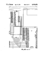
- FIG. 4 is a detailed schematic of the graphics adapter circuit.
- FIG. 5 is a schematic diagram of a daughter board for implementing the companion module of FIG. 2.
- FIG. 6 is a block diagram of the Enhanced Graphics Controller module of FIG. 3.
- FIG. 7 is a representation of the memory mapping and shift register format in 16 color modes.
- FIG. 8 is a representation of the memory mapping and shift register format in 4-color chain modes.
- FIG. 9 is a representation of the memory mapping and shift register format in the new 4-color high resolution modes
- FIG. 10 is a representation of the memory mapping and shift register format in the 4-color CGA modes.
- FIG. 1 is a block diagram of a display system 10 for practicing the invention.
- Display system 10 comprises a graphics adapter 12, a high resolution companion module 14, a display monitor 16, and a high frequency clock 20.
- Clock 20 is divided by 2 by companion module 14 and the resulting clock signal is coupled to graphics adapter 12 where it is used as the dot clock.
- a system bus 22 couples data, address, and control signals from the computer's central processing unit (CPU) (not shown) to graphics adapter 12.
- CPU central processing unit
- the signals from the CPU configure the internal state of graphics adapter 12, including the video memory.
- Graphics adapter 12 generates two pixels (of two bits each in this embodiment) per dot clock cycle. These two pixels are transmitted in parallel to high resolution companion module 14.
- Companion module 14 serializes the two pixels and transmits them to monitor 16 at the rate of one pixel per high frequency clock cycle.
- High frequency clock 20 is also input to monitor 16 for clocking in pixels.
- Monitor 16 thus receives pixels at a rate which is twice the dot clock frequency at which graphics adapter 12 is operating.
- the resolution of the display on monitor 16 is twice the maximum resolution which is normally produced by the graphics adapter at its maximum clock rate.
- a graphics adapter capable of operating at a maximum frequency of 30 megahertz can effectively generate pixels at the rate of 60 megahertz.
- the maximum resolution for 4-color graphics can be increased, for example, to at least 1280 ⁇ 350; with 256 Kb of display memory, any arrangement of up to 1,024,000 pixels may be generated.
- Graphics adapter 12 of FIG. 1 is an IBM EGA compatible adapter.
- the term "EGA-Compatible” has a specific meaning well-known in the art.
- An EGA compatible adapter is one that interacts with the software and hardware to produce the same results as the EGA.
- an EGA-compatible adapter has at least the functionality and programmability described in the publicly available IBM publication, "IBM Enhanced Graphics Adapter", August 2, 1984, EGA adapters are generally provided as boards which can be inserted in the computer's expansion slots, but they can be built into the computer's circuitry.
- Companion module 14 performs two functions: (1) it serializes the 2 pixels received in parallel from graphics adapter 12 and (2) it acts as a video line driver for interfacing the video signals from graphics adapter 12 to the monitor. When the high resolution mode is not in effect, it can act as a simple video line driver. Companion module 14 can be substituted for the video line driver in the graphics adapter. Alternatively, companion module 14 can be put on a "daughter board" along with a high speed clock source, and coupled to the feature connector on the EGA board.
- FIG. 2 a block diagram of companion module 14 of FIG. 1 is shown.
- VDEN 24, and HIRESEN 26 are used to properly configure the companion module.
- Table I shows the 6 valid combinations of these three inputs.
- the first two cases (1,2) are used when the companion module is on a daughter board coupled to the feature connector.
- VDEN is pulled low to disable the "video line driver only" function.
- HIRESEN is pulled high to enable the high resolution mode.
- the VDEN and HIRESEN signals are controlled by a jumper block.
- the INTERNL signal is under the control of the software which programs the EGA (described below with reference to programming of miscellaneous output register). If INTERNL is low (case 1), the companion module outputs are tristated (high impedance) and the EGA directly drives the monitor. When INTERNL is high, the high resolution mode is in effect and the companion module serializes the pixels and drives the monitor. The outputs of the video line driver on the main EGA board are tristated by the high INTERNL signal.
- the last four cases (3-6) are used when the companion module replaces the video line driver on the EGA board.
- the VDEN signal is high in all four cases, enabling the video line driver function.
- HIRESEN is low, allowing the feature connector to be used for some other purpose.
- INTERNL is low (case 3)
- the companion module functions only as a video line driver and its outputs follow its inputs.
- INTERNL is high (case 4)
- the companion module outputs are tristated (high impedance). (Daughter board attached to feature connector drives monitor.)
- HIRESEN is high, and the feature connector cannot be used.
- INTERNL is low (case 5), the companion module functions as a video line driver and its outputs follow its inputs.
- INTERNL is high (case 6), the high resolution mode is in effect and the companion module serializes the pixels and drives the monitor.
- high frequency clock 20 (up to 60 mhz) is input to the companion module at CLKIN 28.
- High frequency clock 20 is coupled to frequency divider 30.
- Frequency divider 30 divides the output of high-frequency clock 20 by two to generate (on line 31) a square wave of one-half the frequency of the high-frequency clock.
- This slower clock is output at CLKOUT 32 for input to the EGA graphics adapter (where the leading or trailing edge is used as the dot clock), and it is also coupled to the select input of multiplexer (mux) 34 and to latch 51.
- the 4 parallel bits 36 representing the two pixels per cycle from the EGA are coupled to mux 34 which serializes the pixels.
- multiplexer 34 selects one of the two pixels (two of the 4 mux inputs) for output on lines 38; when the clock is low (other half of a dot clock cycle) it selects the other pixels (the other two input lines).
- the selected pixel bits are coupled to a color translator 40.
- a two-bit color select signal from the EGA is received at companion module inputs 42 and coupled directly to color translator 40.
- Color translator 40 uses this color select signal to select one of four sets of four colors each, and translates each pixel into one of the four colors in the selected color set. If the signal received at the MONO input 44 is high, the video outputs are configured for a monochrome monitor.
- the outputs are configured for a color monitor.
- the translator outputs are coupled to multiplexer 47, which, in response to the INTERNL signal, selects either the color translator outputs (INTERNL high) or the unmodified) color inputs 36, 42.
- the selected outputs from mux 47 are coupled to video line driver 48, which generates output signals in the appropriate form for driving the display monitor.
- Vertical and horizontal synchronization signals 46 are passed through the video driver to the monitor.
- the video outputs from companion module 14 are suitable for use with TTL digital interface monitors, such as those monitors used with the IBM PC and compatible computers.
- the color selections provided by color translator 40 are shown in Table II.
- the logic equations for the companion module, including color translator 40, are given in Table III.
- the OE equation (Output Enable) of Table III is used by OE calculator 49 for enabling the outputs of video driver 48.
- OE Calculator 49 disables video line driver 48, causing the outputs of video line driver 48 to assume a high-impedance state.
- the CE equation (Clock Enable) of Table III is used by Clock Output Enable 50 for enabling output Clkout 32.
- CLKOUT is high-impedance.
- all companion chip outputs are high-impedance; in case 3, CLKOUT is high-impedance so that another external clock may be supplied through the feature connector.
- a bus interface module 52 provides bus interface, memory select and I/O select logic functions.
- Bus interface 52 of this embodiment is a single integrated circuit chip 82A436 available from Chips and Technologies, Inc., of Milpitas, California.
- a multiplexer 54 is coupled to bus interface module 52 for selecting an internal or external clock source (ext. osc).
- An enhanced graphics controller module 56 is coupled to address buffer 58, bus interface 52, and to video display memory 72 for generating the display signals.
- Enhanced graphics controller module 56 is a single integrated circuit chip 82C435 also available from Chips and Technologies, Inc.
- Enhanced graphics controller module 56 is used for implementing an EGA compatible graphics adapter for IBM and IBM-compatible personal computers.
- the data sheet for the Chips and Technologies Enhanced Graphics Controller chip and the Bus Interface chip is publicly available from Chips and Technologies, Inc.
- FIG. 4 is a detailed schematic for implementing the circuit of FIG. 3.
- the companion module can replace video line driver 58, which is a 74LS244 tri-state buffer.
- a daughter board with a high frequency clock and a companion module can be coupled to feature connector 59.
- a schematic of a daughter board containing companion module 14, clock 20, and connections to feature connector 59, is shown in FIG. 5.
- enhanced graphics controller 56 comprises four primary modules: graphics controller 62, sequencer 64, attributes controller 66, and CRT controller 68.
- Graphics controller 62 interfaces the eight bit CPU data bus 70 to display memory 72. It supports different types of pixel mappings for read and write operations.
- Graphics controller 62 is also responsible for directing data from display memory 72 to attributes controller 68.
- Attributes controller 68 provides a color palette and formats data from display memory 72 for display on the monitor.
- attributes controller 68 In text mode, attributes controller 68 generates the video data stream from the font pattern and attribute code. Sequencer 64 generates the timing signals for the other modules in the graphics control circuit and the memory control signals for display memory 72. CRT controller 66 generates all of the sync and timing signals for the monitor and also generates the multiplexed display memory row and column addresses for display refresh and CPU access to display memory 72.
- Each of the modules in the Enhanced Graphics controller 56 contains registers which can be programmed with predetermined values to configure controller 56 in a particular state, or video mode.
- the programming of these registers is performed by software executing on the computer's cpu, usually with the assistance of the BIOS software stored in BIOS ROM (60, FIG. 3).
- the registers are programmed through I/O ports accessible thru the cpu's I/O address space. The precise method of addressing each register is described in the Chips and Technologies data sheet referenced hereinabove.
- the video mode determines (1) the type of monitor which can be used for the display; (2) whether text or all points addressable (APA) graphics is generated; (3) the resolution of the display; (4) the number of colors in the display (5) the amount of display memory; and (6) the mapping of the display memory into the cpu address space.
- Table IV shows the register settings for these known modes. There are 18 known video modes, but the available modes are limited by the type of monitor and amount of memory available.
- the maximum resolution heretofore available is 640 ⁇ 350 in either 16 colors (with 128 K or more of memory) or 4 colors (with 64 k memory).
- the invention discloses a new technique for configuring an EGA-compatible adapter to produce a new graphics mode for generating 2 2-bit pixels per dot clock cycle. This is accomplished by programming the registers with a new combination of values (described in detail below) which has not previously been known to produce useful results.
- the video mode determines how software executing on the cpu views the video memory.
- the video memory is addressed as an extension of the memory associated with the cpu.
- the address and organization of the video memory, as seen by the software, varies with the video mode and is critical to proper operation of the software.
- the video memory of an EGA is physically organized into 4 planes.
- the video memory comprises 8 64 k ⁇ 4 DRAM chips, with each plane comprising 2 of these memory chips.
- Each plane is a 64 k ⁇ 8 memory space, where an access to a single address reads or writes an 8-bit value (a byte).
- the total memory space is 256 k bytes.
- All 4 planes are accessed during a CRT read, using a single memory address to access 4 bytes. Similarly, all 4 planes can be accessed during a CPU read/write cycle.
- a single cpu address A(P) refers to a byte of 8 pixels (P0-P7).
- Each pixel Pn has a "depth" of 4 bits (M0Dn-M3Dn, one bit in each plane), where the value of these 4 bits determines the color of that pixel (for 16 possible colors).
- Each plane is referred to as a color plane.
- the cpu cannot directly address individual bits of the 4 bit color, because they are all at the same cpu address; instead, color is manipulated indirectly thru register settings.
- the video memory address "window" 80 seen by the processor is thus a bit-map with each bit corresponding to a screen pixel, independent of the color of that pixel. The maximum possible resolution is determined by the size of this window, which is equal to the size of a single plane.
- this memory organization facilitates the access to memory from the display side.
- a single access to all 4 planes loads 4 8 bit shift registers SR0 92, SR1 94, SR2 96, SR3 98 with the data for displaying 8 4-bit pixels.
- One pixel per dot clock is shifted out of the shift registers as 4 parallel bits 100 (one from each plane).
- These 4 bits are sent to the attributes control module where the pixel bit pattern selects one of 16 color registers.
- Each color register contains a 6 bit color code.
- the 6 bits from the selected register are sent to the video driver where they are converted to an appropriate signal to drive the monitor. In this embodiment, all six lines are sent to the monitor as parallel inputs.
- the video driver may create a composite video signal on an RF carrier).
- the 16 6-bit color registers in the Attributes module are programmable to select the 16 colors to be displayed on the screen (out of the 64 possible combinations which can be formed from 6 bits).
- the 4 bit pixel bit pattern stored in the display memory for each pixel serves as an index to select one of these 16 registers, which are collectively referred to as the palette.
- the maximum rate at which pixels can be provided to the display system in this mode is thus determined by the dot clock.
- One 4 -bit pixel is sent per dot clock cycle. (In mode D, the dot clock is half the frequency of the input clock.)
- two logical planes instead of four are provided, effectively increasing the window to 32 Kb. Since the memory is still physically organized in 4 planes, the EGA registers are programmed to logically chain plane M1 to plane M0 and plane M3 to plane M2.
- A(P) A(Q).
- all 4 planes are accessed and 4 bytes placed into the shift registers in the same format as in 16 color modes as shown.
- the bits are shifted out of the shift registers, only the bits from shift registers SR0 and SR2 are used by the attributes module to determine the color; the other two bits are forced to zero (by programming bits 1 and 3 in the color plane enable register to zero) before accessing the palette registers.
- the first 16 bits shifted out define pixels PQ-P7. As the bits are shifted out of the even registers SR0 92 and SR2 96, the bits from odd registers SR1 94 and SR3 98 are shifted in.
- the registers are not reloaded after 8 dot clocks, and the bits from the odd planes (M1 and M3) are shifted out during the next 8 dot clocks. These are the 16 bits which define the next 8 pixels, Q0-Q7 as viewed by the cpu.
- This mode is called chain mode and produces a display of 640 ⁇ 350 with 4 colors, using only 64 Kb of video memory. This mode also generates one pixel per dot clock.
- FIG. 9 illustrates the logical memory organization of the high resolution mode.
- the odd/even chaining of planes is used, but the shift registers are formatted differently and loaded more frequently (every 8 dot clocks) than in chain mode.
- Even numbered bits from planes M0 and M1 are loaded into shift register SR0 92.
- Even numbered bits from planes M2 and M3 are loaded into shift register SR2 96.
- Odd numbered bits from plane M0 and M1 are loaded into shift register SR1 94.
- Odd numbered bits from planes M2 and M3 are loaded into shift register SR3 98.
- bits which define adjacent pixels are loaded into different shift registers. These bits are shifted out together in one dot clock cycle. In the first dot clock cycle, bits M0P6, M0P7, M2P6, and M2P7 are shifted out. These are all of the bits for pixels P6 and P7. In 4 dot clocks, the bits for the 8 pixels P0-P7 are shifted out. In the next 4 dot clocks, the bits for the 8 pixels Q0-Q7 are shifted out. The bits from all 4 planes are shifted out in 8 dot clocks to generate 16 pixels of 2 bits each in 8 dot clocks. 256 Kb of video memory is used. The window to the processor is 128 Kb.
- Table IV shows the register values used to initialize the EGA to configure it in the high resolution mode.
- the manner of addressing the various registers is described in detail in the Chips and Technologies data sheet referenced hereinabove.
- the critical register settings are described below; the others may be set as shown in Table IV or as desired.
- Bits 3 and 2 are set to 1 and 0 respectively to select an external clock source. This selects the ext osc input (FIG. 3) so that the high frequency clock divided by 2 is used as the basic dot clock for the EGA.
- Bit 4 is set to one. This causes the "INTERNL" signal input to the companion module (FIG. 2) to go high to indicate to the companion module that the high resolution mode is in effect. This provides software control over the state of the companion module.
- Bit 0 is set to 1 to generate character clocks which are 8 dot clocks wide. This is standard for graphics modes. Bit 1 is set to 0 for high memory bandwidth for the CRT/memory accesses. This is required for horizontal resolution of 640 pixels or more. Bit 2 is set to 0 so that the shift registers (display serializers) are loaded once every character clock. (In chain modes F, 10, this bit is set to 1.) Bit 3 is set to 0 to select the master clock as the dot clock. Bit 4 set to one to set the cpu memory bandwidth for high frequency (25 mhz) operation.
- Bits 0-3 are all set to one to enable all 4 planes for CPU access.
- Bit 0 is set to 0 for graphics modes. Bit 1 is set to 1 to indicate that 256 Kb of display memory is present. Bit 2 is set to 0 to put the sequencer in odd/even mode. In odd/even mode, even processor addresses access planes 0 and 2. Odd processor addresses access planes 1 and 3.
- the Attributes Controller normally provides a palette of 16 6 bit registers.
- the 4 low order bits of these registers are programmed to match the register index value and thereby pass thru the 4 bit input value.
- palette register 1 is programmed to 0001
- register 2 is set to 0010, etc.
- the 4 bits do not represent a single pixel, but in fact represent 2 pixels to 2 bits each. The translation of these bits into colors is thus postponed until after the pixels are serialized.
- the 4 low order bits are translated by the companion module (inputs 36, FIG. 2).
- the high order bits 4 and 5 in the color registers are used by the companion module (inputs 42, FIG.
- bits 0-3 will select a single color.
- These upper 2 bits may be all set to the same value, or may be set to other values. The latter case can be used to produce a display of 16 colors, where the color representation of a given value of a pixel in memory will actually depend on the value of the adjacent pixel.
- Bit 0 is set to 1 to select graphics mode.
- Bit 3 is set to 0 to disable blinking.
- All 4 planes are enabled by setting bits 0-3 to 1. All 4 bits are used by the Attributes module.
- bit 0 should equal bit 1 and bit 2 should equal bit 3 for predictable results.
- Bits 0-3 refer to the 4 color planes. In odd/even modes, planes 0 and 1 refer to the same color bit for different pixels, and planes 2 and 3 refer to the other color bit for different pixels.
- Bits 0,1, and 2 in this register are set to either 000 (select map 0) or 010 (select map 2).
- the selection determines which plane is read by the processor in read mode 0.
- map 0 selects the 0/1 plane combination (plane 0 for even processor addresses and plane 1 for odd processor addresses).
- Map 2 selects the 2/3 plane combination (plane 2 for even addresses and plane 3 for odd addresses.)
- Bit 4 is set to 1 to select odd/even addressing mode, as described above with reference to the sequencer registers.
- Bit 5 is set to 1.
- this bit is set to 1, the registers are formatted as shown in FIG. 9. Even numbered bits from planes M0 and M1 are loaded into shift register SR0. Even numbered bits from planes M2 and M3 are loaded into shift register SR2. Odd numbered bits from plane M0 and M1 are loaded into shift register SR1. Odd numbered bits from planes M2 and M3 are loaded into shift register SR3.
- this shift register format is used to provide 4-color CGA emulation.
- the memory mapping model of the 4-color CGA emulation is shown in FIG. 10. Planes M0 and M1 are chained and planes M2 and M3 are ignored.
- 4-color CGA mode two adjacent bits define a pixel of one of 4 possible colors.
- the mapping of video memory into cpu memory is direct; that is, a 2 bit pixel occupies two adjacent bits in cpu memory and in video memory.
- the software views a byte (8 bits) as 4 pixels, without the "depth" dimension that is characteristic of EGA modes. In effect, there is only one plane (planes M0 and M1 chained together).
- the shift registers are loaded as shown.
- bits that are shifted out of SR0 and SR1 are the 2 adjacent bits that define a pixel . . . e.g., bits P6/P7, then P4/P5, P2/P3,P0/P1 (all from plane M0) then Q6/Q7,Q4/Q5,Q2/Q3, and Q0/Q1 (all from plane M1).
- bits P6/P7, then P4/P5, P2/P3,P0/P1 all from plane M0
- Q6/Q7,Q4/Q5,Q2/Q3, and Q0/Q1 all from plane M1
- 8 dot clocks 8 2-bit pixels are shifted out in the proper sequence and in parallel pairs.
- Miscellaneous Graphics Controller Register is "FF"; 11 in bits 2 and 3 maps the display memory into processor memory at locations B8000h-BFFFFh for CGA emulation.
- the bits in the shift registers are therefore shifted out at the rate of 1 bit every 2 input clocks and the registers are loaded every 16 input clocks;
- Attributes-Color Plane Enable Register is set to 03-only planes 0 and 1 are enabled. The bits from the other planes are forced to 0 as they are shifted out of shift registers SR2 and SR3.
- the shift register format which has heretofore only been used for these CGA compatible modes 4 and 5 is combined with other registers settings, which are much different from those used in CGA modes, to produce a new mode. All 4 planes are enabled; when the bits are shifted out of the shift registers, all 4 parallel bits are used to represent a pair of 2 bit pixels.
- the software view of memory organization is more similar to the view from "chain modes" (F, 10) (FIG. 8) than to the view from CGA modes (FIG. 10) because of the 2-bit depth. This is advantageous because it means that software written for chain modes can be used in the new, high resolution mode, with it only being necessary to modify the initialization of registers to conform to the new mode settings.
- bit 1 of the Memory mode register of the graphics controller is set to 1 in high resolution mode, 0 in chain modes; (2) loading the shift registers in the format produced by setting bit 5 of the graphics mode register to 1, not 0 as in chain modes; (3) reloading the shift registers every 8 dot clocks, not every 16 as in chain mode (bit 2 of sequencer clocking mode register is 1 in chain mode; (4) using the bits shifted out of all 4 shift registers, not just the 2 registers used in chain mode (bits 0-3 of Attributes color plane enable register).
- timing registers can be programmed as desired to map the 448,000 (or up to 1,048,576 pixels) pixels into the CRT display. Special considerations apply to the following registers.
- Bit 6 is set to 0 for word mode.
- Bit 5 is set to 1 for address wrap at 64 Kb.
- Bit 3 is set to 0 to increment the memory address counter every character clock. (In chain mode, the memory address counter is incremented every other character clock). If more than 512 scan lines are desired (as set in the vertical total register), then bit 2 should be set to 1 to use the horizontal retrace counter divided by 2 to clock the vertical retrace counter.
- This register should be set to the width of the bitmap (in bytes) divided by 4.
- the width of the bitmap (in bytes) must be a multiple of 4.
- This register is set to zero for one scan line per row.
- the invention discloses a new way of programming a graphics adapter to configure it in a new video mode.
- This new mode differs from previously known modes in that two pixels are generated in each clock cycle.
- the invention further provides a companion module for serializing the two pixels to generate one pixel per cycle at a frequency of twice the frequency of the graphics adapter system's dot clock.
Abstract
Description
              TABLE I
______________________________________
HIRESEN      VDEN    INTERNL
______________________________________
(1) H            L       L         EGA drives
(2) H            L       H         HIRES mode
(3) L            H       L         Driver only
(4) L            H       H         FC in use
(5) H            H       L         Driver only
(6) H            H       H         HIRES mode
______________________________________
              TABLE II
______________________________________
VIDIN5-6
        COLOR0    COLOR1     COLOR2  COLOR3
______________________________________
MONO = 0
00      Black     White      Grey    Br. White
01      Black     Cyan       Red     White
10      Black     Green      Red     Yellow
11      Black     Cyan       Magenta White
MONO = 1
00      Black     White      Black   Br. White
01      Black     White      Black   Br. White
10      Black     White      Black   Br. White
11      Black     White      Black   Br. White
______________________________________
                                  TABLE III
__________________________________________________________________________
CLK =    CLKIN/2;
CE =     !HIRESEN# (!INTERNL & HIRESEN & !VDEN
OE =     (!INTERNL & VDEN) # (INTERNL & HIRESEN);
NORMAL = !INTERNAL & VDEN;
ACCEL =  INTERNL & HIRESEN;
VX0 =    Bin & !CLK # Rin & CLK ;
VX1 =    Gin & !CLK # BSin & CLK ;
C0 =     !RSin & !GSin;
                 /*Color Set 0*/
C1 =     !RSin & GSin;
                 /*Color Set 1*/
C2 =      RSin & !GSin;
                 /*Color Set 2*/
C3 =      RSin & GSin;
                 /*Color Set 3*/
P0 =     !VX1 & !VX0;
                 /*Color Code 0*/
P1 =     !VX1 & VX0;
                 /*Color Code 1*/
P2 =     VX1 & !VX0;
                 /*Color Code 2*/
P3     = VX1 & VX0;/*Color Code 3*/
Bout   = ((((C0 # C2 # C3) & (P1 # P3)) #
         (C0 & P2)) & !MONO) & ACCEL # (Bin & NORMAL);
Gout   = ((P1 #  P3) & !MONO) & ACCEL # (Gin & NORMAL) ;
Rout   = ((((C0 # C1 # C2) & (P2 # P3)) # (C3 &
         (P1 # P3))) & !MONO) & ACCEL # (Rin & NORMAL);
BSout  = ((((C3 & (P2 # P3))) & !MONO) #
         ((P1 # P3) & MONO)) & ACCEL # (BSin & NORMAL);
GSout  = ((((C3 & (P2 # P3))) & !MONO) #
         ((P2 # P3) & MONO)) & ACCEL #GSin & NORMAL);
RSout  = (((C3 & (P2 # P3))) & !MONO) & ACCEL #
         (RSin & NORMAL);
__________________________________________________________________________
 LEGEND
 ! = not
 # = or
 & = and
TABLE IV External Registers Register Mode of OperationName Part Index 0 1 2 3 4 5 6 7 D E F 10 F** 10** 0* 1* 2* 3* Miscellaneous 3C2 -- 23 23 23 23 23 23 23A6 23 23 A2 A7 A2 A7 A7 A7 A7 A7 BB Feature Cntrl 37A -- 00 00 00 00 00 00 00 00 00 00 00 00 00 00 00 00 00 00 00Input Stat 0 3C2 -- -- -- -- -- -- -- -- -- -- -- -- -- -- -- -- -- -- --Input Stat 1 37A -- -- -- -- -- -- -- -- -- -- -- -- -- -- -- -- -- -- -- ? = B in monochrome modes ? = D in color modes *Values for these modes when the IBM Enhanced Color Display is attached **Values for these modes when greater than 64K Graphics Memory is installed Sequencer Registers Register Mode of Operation Name Part Index 0 1 2 3 4 5 6 7 D E F 10 F** 10** 0* 1* 2* 3* Seq Address 3C4 -- -- -- -- -- -- -- -- -- -- -- -- -- -- -- -- -- -- -- Reset 3C5 00 03 03 03 03 03 03 03 03 03 03 03 03 03 03 03 03 03 03 03 Clock Mode 3C5 01 0B 0B 01 01 0B 0B 01 00 0B 01 05 05 01 01 0B 0B 01 01 01 Map Mask 3C5 02 03 03 03 03 03 03 01 03 0F 0F 0F 0F 0F 0F 03 03 03 03 0F Char Gen Sel 3C5 03 00 00 00 00 00 00 00 00 00 00 00 00 00 00 00 00 00 00 00 Memory Mode 3C5 04 03 03 03 03 02 02 06 03 06 06 00 00 06 06 03 03 03 03 02 *Values for these modes when the IBM Enhanced Color Display is attached **Values for these modes when greater than 64K Graphics Memory is installed Graphics SI Registers Register Mode of Operation Name Part Index 0 1 2 3 4 5 6 7 D E F 10 F** 10** 0* 1* 2* 3* Grphx I Pos 3CC -- 00 00 00 00 00 00 00 00 00 00 00 00 00 00 00 00 00 00 00 Grphx II Pos 3CA -- 01 01 01 01 01 01 01 01 01 01 01 01 01 01 01 01 01 01 01 Grphx III AD 3CE -- -- -- -- -- -- -- -- -- -- -- -- -- -- -- -- -- -- -- Set Reset 3CF 00 00 00 00 00 00 00 00 00 00 00 00 00 00 00 00 00 00 00 00 Enable S/R 3CF 01 00 00 00 00 00 00 00 00 00 00 00 00 00 00 00 00 00 00 00 Color Compare 3CF 02 00 00 00 00 00 00 00 00 00 00 00 00 00 00 00 00 00 00 00 Data Rotate 3CF 03 00 00 00 00 00 00 00 00 00 00 00 00 00 00 00 00 00 00 00 Read Map Sel 3CF 04 00 00 00 00 00 00 00 00 00 00 00 00 00 00 00 00 00 00 00 Mode Register 3CF 05 10 10 10 10 30 30 00 10 00 00 10 10 00 00 10 10 10 10 30 Miscellaneous 3CF 06 0E 0E 0E 0E 0F 0F 0D 0A 05 05 07 07 05 05 0E 0E 0E 0E 03 Color No Care 3CF 07 00 00 00 00 00 00 00 00 0F 0F 0F 0F 0F 0F 00 00 00 00 OF Bit Mask 3CF 08 FF FF FF FF FF FF FF FF FF FF FF FF FF FF FF FF FF FF FF *Values for these modes when the IBM Enhanced Color Display is attached *Values for these modes when greater than 64K Graphics Memory is installe CRT Controller Registers (1 of 2) Name Part Index 0 1 2 3 4 5 6 7 D E F 10 F* 10* 0* 1* 2* 3* Address Reg 374 -- -- -- -- -- -- -- -- -- -- -- -- -- -- -- -- -- -- -- Hortz Total 375 00 37 37 70 70 37 37 70 60 37 70 60 5B 60 5B 2D 2D 5B 5B 8C Hrz Disp End 375 01 27 27 4F 4F 27 27 4F 4F 27 4F 4F 4F 4F 4F 27 27 4F 4F 6B Strt Hrz Blk 375 02 2D 2D 5C 5C 2D 2D 59 56 2D 56 56 53 56 53 2B 2B 53 53 70 End Hrz Blk 375 03 37 37 2F 2F 37 37 2D 3A 37 2D 1A 17 3A 37 2D 2D 37 37 20 Strt Hrz Retr 375 04 31 31 5F 5F 30 30 5E 51 30 5E 50 50 50 52 28 28 51 51 76 End Hrz Retr 375 05 15 15 07 07 14 14 06 60 14 06 E0 BA 60 00 6D 6D 5B 5B 04 Vert Total 375 06 04 04 04 04 04 04 04 70 04 04 70 6C 70 6C 6C 6C 6C 6C 6C Overflow 375 07 11 11 11 11 11 11 11 1F 11 11 1F 1F 1F 1F 1F 1F 1F 1F 1F Preset Row SC 375 08 00 00 00 00 00 00 00 00 00 00 00 00 00 00 00 00 00 00 00 Max Scan Line 375 09 07 07 07 07 01 01 01 0D 00 00 00 00 00 00 0D 0D 0D 0D 00 Cursor Start 375 0A 06 06 06 06 00 00 00 0B 00 00 00 00 00 00 0B 0B 0B 0B 00 Cursor End 375 0B 07 07 07 07 00 00 00 0C 00 00 00 00 00 00 0C 0C 0C 0C 00 Strt Addr Hi 375 0C -- -- -- -- -- -- -- -- -- -- -- -- -- -- -- -- -- -- 00 Strt Addr Le 375 0D -- -- -- -- -- -- -- -- -- -- -- -- -- -- -- -- -- -- ? = B in monochrome modes ? = D in color modes *Values for these modes when the IBM Enhanced Color Display is attached *Values for these modes when greater than 64K Graphics Memory is installe CRT Controller Registers (2 of 2) Register Mode of Operation Name Part Index 0 1 2 3 4 5 6 7 D E F 10 F* 10* 0* 1* 2* 3* Cursor LC Hi 375 0E -- -- -- -- -- -- -- -- -- -- -- -- -- -- -- -- -- -- Cursor LC Low 375 0F -- -- -- -- -- -- -- -- -- -- -- -- -- -- -- -- -- -- Wt Retr Strt 375 10 E1 E1 E1 E1 E1 E1 E0 5E E1 E0 5E 5E 5E 5E 5E 5E 5E 5E 5E Light Pen Hi 375 10 -- -- -- -- -- -- -- -- -- -- -- -- -- -- -- -- -- -- Vert Retr End 375 11 24 24 24 24 24 24 23 2E 24 23 2E 2B 2E 2B 2B 2B 2B 2B AB Light Pen Low 375 11 -- -- -- -- -- -- -- -- -- -- -- -- -- -- -- -- -- -- Vrt Disp End 375 12 C7 C7 C7 C7 C7 C7 C7 5D C7 C7 5D 5D 5D 5D 5D 5D 5D 5D 5D Offset 375 13 14 14 28 28 14 14 28 28 14 28 14 14 28 28 14 14 28 28 1D Underline Loc 375 14 08 08 08 08 00 00 00 0D 00 00 0D 0F 0D 0F 0F 0F 0F 0F 1F Strt Vert Blk 375 15 E0 E0 E0 E0 E0 E0 DF 5E E0 DF 5E 5F 5E 5F 5E 5E 5E 5E 5F End Vert Blk 375 16 F0 F0 F0 F0 F0 F0 EF 6E F0 EF 6E 0A 6E 0A 0A 0A 0A 0A EA Mode Control 375 17 A3 A3 A3 A3 A2 A2 C2 A3 E3 E3 8B 8B E3 E3 A3 A3 A3 A3 A3 Line Compare 375 18 FF FF FF FF FF FF FF FF FF FF FF FF FF FF FF FF FF FF FF ? = B in monochrome modes ? = D in color modes *Values for these modes when the IBM Enhanced Color Display is attached *Values for these modes when greater than 64K Graphics Memory is installe Attribute Registers (1 of 2) Register Mode of Operation Name Part Index 0 1 2 3 4 5 6 7 D E F 10 F* 10* 0* 1* 2* 3* Address 37A -- -- -- -- -- -- -- -- -- -- -- -- -- -- -- -- -- -- -- Palette 3C0 00 00 00 00 00 00 00 00 00 00 00 00 00 00 00 00 00 00 00 00 Palette 3C0 01 01 01 01 01 13 13 17 08 01 01 08 01 08 01 01 01 01 01 01 Palette 3C0 02 02 02 02 02 15 15 17 08 02 02 00 00 00 02 02 02 02 02 02 Palette 3C0 03 03 03 03 03 17 17 17 08 03 03 00 00 00 03 03 03 03 03 03 Palette 3C0 04 04 04 04 04 02 02 17 08 04 04 18 04 18 04 04 04 04 04 04 Palette 3C0 05 05 05 05 05 04 04 17 08 05 05 18 07 18 05 05 05 05 05 05 Palette 3C0 06 06 06 06 06 06 06 17 08 06 06 00 00 00 06 14 14 14 14 06 Palette 3C0 07 07 07 07 07 07 07 17 08 07 07 00 00 00 07 07 07 07 07 07 Palette 3C0 08 10 10 10 10 10 10 17 10 10 10 00 00 00 38 38 38 38 38 08 Palette 3C0 09 11 11 11 11 11 11 17 18 11 11 08 01 08 39 39 39 39 39 09 Palette 3C0 0A 12 12 12 12 12 12 17 18 12 12 00 00 00 3A 3A 3A 3A 3A 0A Palette 3C0 0B 13 13 13 13 13 13 17 18 13 13 00 00 00 3B 3B 3B 3B 3B ? = B in monochrome modes ? = D in color modes *Values for these modes when the IBM Enhanced Color Display is attached *Values for these modes when greater than 64K Graphics Memory is installe Attribute Registers (2 of 2) Register Mode of Operation Name Part Index 0 1 2 3 4 5 6 7 D E F 10 F* 10* 0* 1* 2* 3* Palette 3C0 0C 14 14 14 14 14 14 17 18 14 14 00 04 00 3C 3C 3C 3C 3C 0C Palette 3C0 0D 15 15 15 15 15 15 17 18 15 15 18 07 18 3D 3D 3D 3D 3D 0D Palette 3C0 0E 16 16 16 16 16 16 17 18 16 16 00 00 00 3E 3E 3E 3E 3E 0E Palette 3C0 0F 17 17 17 17 17 17 18 17 17 00 00 00 3F 3F 3F 3F 3F 3F 0F Mode Control 3C0 10 06 06 06 06 01 01 01 0E 01 01 0B 0B 0B 01 0B 0B 0B 0B 01 Overscan 3C0 11 00 00 00 00 00 00 00 00 00 00 00 00 00 00 00 00 00 00 00 Color Plane 3C0 12 0F 0F 0F 0F 03 03 01 0F 0F 0F 05 05 05 0F 0F 0F 0F 0F 0F Hrz Panning 3C0 13 00 00 00 00 00 00 00 00 00 00 00 00 00 00 00 00 00 00 00 *Values for these modes when the IBM Enhanced Color Display is attached *Values for these modes when greater than 64K Graphics Memory is installe
Claims (13)
Priority Applications (1)
| Application Number | Priority Date | Filing Date | Title |
|---|---|---|---|
| US07/076,099 US4918436A (en) | 1987-06-01 | 1987-07-21 | High resolution graphics system |
Applications Claiming Priority (2)
| Application Number | Priority Date | Filing Date | Title |
|---|---|---|---|
| US5684787A | 1987-06-01 | 1987-06-01 | |
| US07/076,099 US4918436A (en) | 1987-06-01 | 1987-07-21 | High resolution graphics system |
Related Parent Applications (1)
| Application Number | Title | Priority Date | Filing Date |
|---|---|---|---|
| US5684787A Continuation-In-Part | 1987-06-01 | 1987-06-01 |
Publications (1)
| Publication Number | Publication Date |
|---|---|
| US4918436A true US4918436A (en) | 1990-04-17 |
Family
ID=26735769
Family Applications (1)
| Application Number | Title | Priority Date | Filing Date |
|---|---|---|---|
| US07/076,099 Expired - Lifetime US4918436A (en) | 1987-06-01 | 1987-07-21 | High resolution graphics system |
Country Status (1)
| Country | Link |
|---|---|
| US (1) | US4918436A (en) |
Cited By (23)
| Publication number | Priority date | Publication date | Assignee | Title |
|---|---|---|---|---|
| WO1990015395A1 (en) * | 1989-06-02 | 1990-12-13 | Atari Corporation | Apparatus and method for producing images that include dynamically interactive sprites |
| US5138305A (en) * | 1988-03-30 | 1992-08-11 | Kabushiki Kaisha Toshiba | Display controller |
| US5150109A (en) * | 1989-02-13 | 1992-09-22 | Touchstone Computers, Inc. | VGA controller card |
| US5159683A (en) * | 1986-07-29 | 1992-10-27 | Western Digital Corporation | Graphics controller adapted to automatically sense the type of connected video monitor and configure the control and display signals supplied to the monitor accordingly |
| US5189401A (en) * | 1991-06-14 | 1993-02-23 | Unisys Corporation | AX and EGA video display apparatus utilizing a VGA monitor |
| US5291187A (en) * | 1991-05-06 | 1994-03-01 | Compaq Computer Corporation | High-speed video display system |
| US5404448A (en) * | 1992-08-12 | 1995-04-04 | International Business Machines Corporation | Multi-pixel access memory system |
| US5477242A (en) * | 1994-01-03 | 1995-12-19 | International Business Machines Corporation | Display adapter for virtual VGA support in XGA native mode |
| US5481275A (en) * | 1992-11-02 | 1996-01-02 | The 3Do Company | Resolution enhancement for video display using multi-line interpolation |
| US5506602A (en) * | 1988-07-07 | 1996-04-09 | Canon Kabushiki Kaisha | Display control apparatus and method whereby a display identifies its display control method to a display controller in order that the display controller can configure itself to output the display control signals corresponding to the identified display co |
| WO1996026490A1 (en) * | 1995-02-23 | 1996-08-29 | Alliance Semiconductor Corporation | Method and system for displaying images using a dynamically reconfigurable display memory architecture |
| US5572235A (en) * | 1992-11-02 | 1996-11-05 | The 3Do Company | Method and apparatus for processing image data |
| US5581279A (en) * | 1991-12-23 | 1996-12-03 | Cirrus Logic, Inc. | VGA controller circuitry |
| US5596693A (en) * | 1992-11-02 | 1997-01-21 | The 3Do Company | Method for controlling a spryte rendering processor |
| US5654738A (en) * | 1993-05-17 | 1997-08-05 | Compaq Computer Corporation | File-based video display mode setup |
| US5727139A (en) * | 1995-08-30 | 1998-03-10 | Cirrus Logic, Inc. | Method and apparatus for minimizing number of pixel data fetches required for a stretch operation of video images |
| US5752073A (en) * | 1993-01-06 | 1998-05-12 | Cagent Technologies, Inc. | Digital signal processor architecture |
| US5838389A (en) * | 1992-11-02 | 1998-11-17 | The 3Do Company | Apparatus and method for updating a CLUT during horizontal blanking |
| US5933197A (en) * | 1995-03-15 | 1999-08-03 | Nec Corporation | Display device having a video bandwidth controller |
| US5943029A (en) * | 1996-01-26 | 1999-08-24 | Dell Usa, L.P. | Method and apparatus to provide non-DDC monitor characteristics to system software |
| US6313813B1 (en) | 1999-10-21 | 2001-11-06 | Sony Corporation | Single horizontal scan range CRT monitor |
| US20030043173A1 (en) * | 2001-05-18 | 2003-03-06 | Sun Microsystems, Inc. | Panning while displaying a portion of the frame buffer image |
| US6940496B1 (en) * | 1998-06-04 | 2005-09-06 | Silicon, Image, Inc. | Display module driving system and digital to analog converter for driving display |
Citations (2)
| Publication number | Priority date | Publication date | Assignee | Title |
|---|---|---|---|---|
| US4250502A (en) * | 1978-05-02 | 1981-02-10 | Siemens Aktiengesellschaft | Resolution for a raster display |
| US4673929A (en) * | 1984-04-16 | 1987-06-16 | Gould Inc. | Circuit for processing digital image data in a high resolution raster display system |
-
1987
- 1987-07-21 US US07/076,099 patent/US4918436A/en not_active Expired - Lifetime
Patent Citations (2)
| Publication number | Priority date | Publication date | Assignee | Title |
|---|---|---|---|---|
| US4250502A (en) * | 1978-05-02 | 1981-02-10 | Siemens Aktiengesellschaft | Resolution for a raster display |
| US4673929A (en) * | 1984-04-16 | 1987-06-16 | Gould Inc. | Circuit for processing digital image data in a high resolution raster display system |
Non-Patent Citations (20)
| Title |
|---|
| "82C435 Enhanced Graphics Controller, 82A436 Bus Interface", Chips and Technologies, Jan. 1987, pp. 1-30. |
| "IBM Enhanced Graphics Adapter", IBM, Aug. 2, 1984, pp. 1-75. |
| 82C435 Enhanced Graphics Controller, 82A436 Bus Interface , Chips and Technologies, Jan. 1987, pp. 1 30. * |
| Charles Petzold; Achieving the Standard: 12 EGA Boards; PC Magazine; pp. 145 182; Aug., 1986. * |
| Charles Petzold; Achieving the Standard: 12 EGA Boards; PC Magazine; pp. 145-182; Aug., 1986. |
| Charles Petzold; Exploring the EGA, Part 1; PC Magazine; pp. 367 384; Sep. 16, 1986. * |
| Charles Petzold; Exploring the EGA, Part 1; PC Magazine; pp. 367-384; Sep. 16, 1986. |
| Charles Petzold; Exploring the EGA, Part 2; PC Magazine; pp. 287 313; Aug., 1986. * |
| Charles Petzold; Exploring the EGA, Part 2; PC Magazine; pp. 287-313; Aug., 1986. |
| IBM Enhanced Graphics Adapter , IBM, Aug. 2, 1984, pp. 1 75. * |
| Petzold, "Achieving the Standard: 12 EGA Boards"; PC Magazine, pp. 145-182, Aug. 1986. |
| Petzold, "Exploring the EGA, Part 1"; PC Magazine, Sep. 1986. |
| Petzold, "Exploring the EGA, Part 2"; PC Magazine, p. 3, Aug. 1988. |
| Petzold, Achieving the Standard: 12 EGA Boards ; PC Magazine, pp. 145 182, Aug. 1986. * |
| Petzold, Exploring the EGA, Part 1 ; PC Magazine, Sep. 1986. * |
| Petzold, Exploring the EGA, Part 2 ; PC Magazine, p. 3, Aug. 1988. * |
| Stewart Alsop, "The Enhanced Graphics Standard Comes of Age", PC Magazine, pp. 141-143, Aug. 1980. |
| Stewart Alsop, The Enhanced Graphics Standard Comes of Age , PC Magazine, pp. 141 143, Aug. 1980. * |
| Stewart Alsop; The Enhanced Graphics Standard Comes of Age; PC Magazine; pp. 141 143; Aug., 1986. * |
| Stewart Alsop; The Enhanced Graphics Standard Comes of Age; PC Magazine; pp. 141-143; Aug., 1986. |
Cited By (30)
| Publication number | Priority date | Publication date | Assignee | Title |
|---|---|---|---|---|
| US5159683A (en) * | 1986-07-29 | 1992-10-27 | Western Digital Corporation | Graphics controller adapted to automatically sense the type of connected video monitor and configure the control and display signals supplied to the monitor accordingly |
| US5138305A (en) * | 1988-03-30 | 1992-08-11 | Kabushiki Kaisha Toshiba | Display controller |
| US5506602A (en) * | 1988-07-07 | 1996-04-09 | Canon Kabushiki Kaisha | Display control apparatus and method whereby a display identifies its display control method to a display controller in order that the display controller can configure itself to output the display control signals corresponding to the identified display co |
| US5150109A (en) * | 1989-02-13 | 1992-09-22 | Touchstone Computers, Inc. | VGA controller card |
| US5235677A (en) * | 1989-06-02 | 1993-08-10 | Atari Corporation | Raster graphics color palette architecture for multiple display objects |
| WO1990015395A1 (en) * | 1989-06-02 | 1990-12-13 | Atari Corporation | Apparatus and method for producing images that include dynamically interactive sprites |
| US5291187A (en) * | 1991-05-06 | 1994-03-01 | Compaq Computer Corporation | High-speed video display system |
| US5790111A (en) * | 1991-05-06 | 1998-08-04 | Compaq Computer Corporation | High-speed video display system |
| US5488393A (en) * | 1991-05-06 | 1996-01-30 | Compaq Computer Corporation | High-speed video display system |
| US5189401A (en) * | 1991-06-14 | 1993-02-23 | Unisys Corporation | AX and EGA video display apparatus utilizing a VGA monitor |
| US5581279A (en) * | 1991-12-23 | 1996-12-03 | Cirrus Logic, Inc. | VGA controller circuitry |
| US5404448A (en) * | 1992-08-12 | 1995-04-04 | International Business Machines Corporation | Multi-pixel access memory system |
| US6191772B1 (en) | 1992-11-02 | 2001-02-20 | Cagent Technologies, Inc. | Resolution enhancement for video display using multi-line interpolation |
| US5838389A (en) * | 1992-11-02 | 1998-11-17 | The 3Do Company | Apparatus and method for updating a CLUT during horizontal blanking |
| US5572235A (en) * | 1992-11-02 | 1996-11-05 | The 3Do Company | Method and apparatus for processing image data |
| US5481275A (en) * | 1992-11-02 | 1996-01-02 | The 3Do Company | Resolution enhancement for video display using multi-line interpolation |
| US5596693A (en) * | 1992-11-02 | 1997-01-21 | The 3Do Company | Method for controlling a spryte rendering processor |
| US5752073A (en) * | 1993-01-06 | 1998-05-12 | Cagent Technologies, Inc. | Digital signal processor architecture |
| US6115026A (en) * | 1993-05-17 | 2000-09-05 | Compaq Computer Corporation | File-based video display mode setup |
| US5654738A (en) * | 1993-05-17 | 1997-08-05 | Compaq Computer Corporation | File-based video display mode setup |
| US5477242A (en) * | 1994-01-03 | 1995-12-19 | International Business Machines Corporation | Display adapter for virtual VGA support in XGA native mode |
| WO1996026490A1 (en) * | 1995-02-23 | 1996-08-29 | Alliance Semiconductor Corporation | Method and system for displaying images using a dynamically reconfigurable display memory architecture |
| US5933197A (en) * | 1995-03-15 | 1999-08-03 | Nec Corporation | Display device having a video bandwidth controller |
| US5727139A (en) * | 1995-08-30 | 1998-03-10 | Cirrus Logic, Inc. | Method and apparatus for minimizing number of pixel data fetches required for a stretch operation of video images |
| US5943029A (en) * | 1996-01-26 | 1999-08-24 | Dell Usa, L.P. | Method and apparatus to provide non-DDC monitor characteristics to system software |
| US6940496B1 (en) * | 1998-06-04 | 2005-09-06 | Silicon, Image, Inc. | Display module driving system and digital to analog converter for driving display |
| US6313813B1 (en) | 1999-10-21 | 2001-11-06 | Sony Corporation | Single horizontal scan range CRT monitor |
| US6816131B2 (en) | 1999-10-21 | 2004-11-09 | Sony Corporation | Single horizontal scan range CRT monitor |
| US20030043173A1 (en) * | 2001-05-18 | 2003-03-06 | Sun Microsystems, Inc. | Panning while displaying a portion of the frame buffer image |
| US6864900B2 (en) * | 2001-05-18 | 2005-03-08 | Sun Microsystems, Inc. | Panning while displaying a portion of the frame buffer image |
Similar Documents
| Publication | Publication Date | Title |
|---|---|---|
| US4918436A (en) | High resolution graphics system | |
| US5257350A (en) | Computer with self configuring video circuitry | |
| US5400057A (en) | Internal test circuits for color palette device | |
| CA2068001C (en) | High definition multimedia display | |
| US4751446A (en) | Lookup table initialization | |
| US4613852A (en) | Display apparatus | |
| US5270687A (en) | Palette devices, computer graphics systems and method with parallel lookup and input signal splitting | |
| US4574277A (en) | Selective page disable for a video display | |
| JP2517123Y2 (en) | Memory device | |
| JPS59186A (en) | Color signal generator for raster scan type video display | |
| US5293468A (en) | Controlled delay devices, systems and methods | |
| US5086295A (en) | Apparatus for increasing color and spatial resolutions of a raster graphics system | |
| EP0298243B1 (en) | A computer video demultiplexer | |
| GB2202978A (en) | Video apparatus employing vrams | |
| EP0734008B1 (en) | Time multiplexing of pixel data out of a video frame buffer | |
| US5420609A (en) | Frame buffer, systems and methods | |
| US4620186A (en) | Multi-bit write feature for video RAM | |
| US5309551A (en) | Devices, systems and methods for palette pass-through mode | |
| US5341470A (en) | Computer graphics systems, palette devices and methods for shift clock pulse insertion during blanking | |
| US5327159A (en) | Packed bus selection of multiple pixel depths in palette devices, systems and methods | |
| JPH0359595A (en) | Matrix display device | |
| EP0148578A2 (en) | Programmable video display generator | |
| US5555460A (en) | Method and apparatus for providing a reformatted video image to a display | |
| US5694585A (en) | Programmable memory controller and data terminal equipment | |
| US5097256A (en) | Method of generating a cursor |
Legal Events
| Date | Code | Title | Description |
|---|---|---|---|
| AS | Assignment |
Owner name: CHIPS AND TECHNOLOGY, INC., 521 COTTONWOOD DRIVE, Free format text: ASSIGNMENT OF ASSIGNORS INTEREST.;ASSIGNOR:JOHARY, ARUN;REEL/FRAME:004742/0105 Effective date: 19870714 Owner name: CHIPS AND TECHNOLOGY, INC.,CALIFORNIA Free format text: ASSIGNMENT OF ASSIGNORS INTEREST;ASSIGNOR:JOHARY, ARUN;REEL/FRAME:004742/0105 Effective date: 19870714 |
|
| STCF | Information on status: patent grant |
Free format text: PATENTED CASE |
|
| FEPP | Fee payment procedure |
Free format text: PAYOR NUMBER ASSIGNED (ORIGINAL EVENT CODE: ASPN); ENTITY STATUS OF PATENT OWNER: LARGE ENTITY |
|
| FPAY | Fee payment |
Year of fee payment: 4 |
|
| FEPP | Fee payment procedure |
Free format text: PAT HLDR NO LONGER CLAIMS SMALL ENT STAT AS INDIV INVENTOR (ORIGINAL EVENT CODE: LSM1); ENTITY STATUS OF PATENT OWNER: LARGE ENTITY |
|
| FPAY | Fee payment |
Year of fee payment: 8 |
|
| FEPP | Fee payment procedure |
Free format text: PAYER NUMBER DE-ASSIGNED (ORIGINAL EVENT CODE: RMPN); ENTITY STATUS OF PATENT OWNER: LARGE ENTITY Free format text: PAYOR NUMBER ASSIGNED (ORIGINAL EVENT CODE: ASPN); ENTITY STATUS OF PATENT OWNER: LARGE ENTITY |
|
| AS | Assignment |
Owner name: CHIPS AND TECHNOLOGIES, LLC, CALIFORNIA Free format text: MERGER;ASSIGNOR:CHIPS AND TECHNOLOGIES, INC.;REEL/FRAME:011333/0503 Effective date: 19981030 |
|
| AS | Assignment |
Owner name: INTEL CORPORATION, CALIFORNIA Free format text: ASSIGNMENT OF ASSIGNORS INTEREST;ASSIGNOR:CHIPS AND TECHNOLOGIES, LLC;REEL/FRAME:011449/0081 Effective date: 20010103 |
|
| FPAY | Fee payment |
Year of fee payment: 12 |
|
| AS | Assignment |
Owner name: CHIPS AND TECHNOLOGIES, LLC, CALIFORNIA Free format text: CORRECTIVE ASSIGNMENT TO CORRECT THE APPLICATION NUMBER FROM 09/207,014 TO 09/027,014 PREVIOUSLY RECORDED AT REEL: 011333 FRAME: 0503. ASSIGNOR(S) HEREBY CONFIRMS THE ASSIGNMENT;ASSIGNOR:CHIPS AND TECHNOLOGIES, INC.;REEL/FRAME:038824/0619 Effective date: 19981030 |