US4917841A - Method of making a refrigerator cabinet liner having non-crinkled corners - Google Patents
Method of making a refrigerator cabinet liner having non-crinkled corners Download PDFInfo
- Publication number
- US4917841A US4917841A US07/254,732 US25473288A US4917841A US 4917841 A US4917841 A US 4917841A US 25473288 A US25473288 A US 25473288A US 4917841 A US4917841 A US 4917841A
- Authority
- US
- United States
- Prior art keywords
- corner
- liner
- flat surface
- vacuum formed
- foam
- Prior art date
- Legal status (The legal status is an assumption and is not a legal conclusion. Google has not performed a legal analysis and makes no representation as to the accuracy of the status listed.)
- Expired - Lifetime
Links
Images
Classifications
-
- F—MECHANICAL ENGINEERING; LIGHTING; HEATING; WEAPONS; BLASTING
- F25—REFRIGERATION OR COOLING; COMBINED HEATING AND REFRIGERATION SYSTEMS; HEAT PUMP SYSTEMS; MANUFACTURE OR STORAGE OF ICE; LIQUEFACTION SOLIDIFICATION OF GASES
- F25D—REFRIGERATORS; COLD ROOMS; ICE-BOXES; COOLING OR FREEZING APPARATUS NOT OTHERWISE PROVIDED FOR
- F25D23/00—General constructional features
- F25D23/06—Walls
- F25D23/062—Walls defining a cabinet
- F25D23/064—Walls defining a cabinet formed by moulding, e.g. moulding in situ
-
- B—PERFORMING OPERATIONS; TRANSPORTING
- B29—WORKING OF PLASTICS; WORKING OF SUBSTANCES IN A PLASTIC STATE IN GENERAL
- B29C—SHAPING OR JOINING OF PLASTICS; SHAPING OF MATERIAL IN A PLASTIC STATE, NOT OTHERWISE PROVIDED FOR; AFTER-TREATMENT OF THE SHAPED PRODUCTS, e.g. REPAIRING
- B29C44/00—Shaping by internal pressure generated in the material, e.g. swelling or foaming ; Producing porous or cellular expanded plastics articles
- B29C44/02—Shaping by internal pressure generated in the material, e.g. swelling or foaming ; Producing porous or cellular expanded plastics articles for articles of definite length, i.e. discrete articles
- B29C44/12—Incorporating or moulding on preformed parts, e.g. inserts or reinforcements
- B29C44/1228—Joining preformed parts by the expanding material
- B29C44/1233—Joining preformed parts by the expanding material the preformed parts being supported during expanding
-
- B—PERFORMING OPERATIONS; TRANSPORTING
- B29—WORKING OF PLASTICS; WORKING OF SUBSTANCES IN A PLASTIC STATE IN GENERAL
- B29C—SHAPING OR JOINING OF PLASTICS; SHAPING OF MATERIAL IN A PLASTIC STATE, NOT OTHERWISE PROVIDED FOR; AFTER-TREATMENT OF THE SHAPED PRODUCTS, e.g. REPAIRING
- B29C44/00—Shaping by internal pressure generated in the material, e.g. swelling or foaming ; Producing porous or cellular expanded plastics articles
- B29C44/02—Shaping by internal pressure generated in the material, e.g. swelling or foaming ; Producing porous or cellular expanded plastics articles for articles of definite length, i.e. discrete articles
- B29C44/12—Incorporating or moulding on preformed parts, e.g. inserts or reinforcements
- B29C44/18—Filling preformed cavities
-
- B—PERFORMING OPERATIONS; TRANSPORTING
- B29—WORKING OF PLASTICS; WORKING OF SUBSTANCES IN A PLASTIC STATE IN GENERAL
- B29C—SHAPING OR JOINING OF PLASTICS; SHAPING OF MATERIAL IN A PLASTIC STATE, NOT OTHERWISE PROVIDED FOR; AFTER-TREATMENT OF THE SHAPED PRODUCTS, e.g. REPAIRING
- B29C51/00—Shaping by thermoforming, i.e. shaping sheets or sheet like preforms after heating, e.g. shaping sheets in matched moulds or by deep-drawing; Apparatus therefor
- B29C51/26—Component parts, details or accessories; Auxiliary operations
- B29C51/30—Moulds
-
- B—PERFORMING OPERATIONS; TRANSPORTING
- B29—WORKING OF PLASTICS; WORKING OF SUBSTANCES IN A PLASTIC STATE IN GENERAL
- B29C—SHAPING OR JOINING OF PLASTICS; SHAPING OF MATERIAL IN A PLASTIC STATE, NOT OTHERWISE PROVIDED FOR; AFTER-TREATMENT OF THE SHAPED PRODUCTS, e.g. REPAIRING
- B29C44/00—Shaping by internal pressure generated in the material, e.g. swelling or foaming ; Producing porous or cellular expanded plastics articles
- B29C44/02—Shaping by internal pressure generated in the material, e.g. swelling or foaming ; Producing porous or cellular expanded plastics articles for articles of definite length, i.e. discrete articles
- B29C44/12—Incorporating or moulding on preformed parts, e.g. inserts or reinforcements
- B29C44/14—Incorporating or moulding on preformed parts, e.g. inserts or reinforcements the preformed part being a lining
-
- B—PERFORMING OPERATIONS; TRANSPORTING
- B29—WORKING OF PLASTICS; WORKING OF SUBSTANCES IN A PLASTIC STATE IN GENERAL
- B29C—SHAPING OR JOINING OF PLASTICS; SHAPING OF MATERIAL IN A PLASTIC STATE, NOT OTHERWISE PROVIDED FOR; AFTER-TREATMENT OF THE SHAPED PRODUCTS, e.g. REPAIRING
- B29C51/00—Shaping by thermoforming, i.e. shaping sheets or sheet like preforms after heating, e.g. shaping sheets in matched moulds or by deep-drawing; Apparatus therefor
-
- B—PERFORMING OPERATIONS; TRANSPORTING
- B29—WORKING OF PLASTICS; WORKING OF SUBSTANCES IN A PLASTIC STATE IN GENERAL
- B29L—INDEXING SCHEME ASSOCIATED WITH SUBCLASS B29C, RELATING TO PARTICULAR ARTICLES
- B29L2031/00—Other particular articles
- B29L2031/762—Household appliances
- B29L2031/7622—Refrigerators
Definitions
- This invention relates to a very thin vacuum formed structure of plastic having non-crinkled corners and a method of making.
- the foam When forming a refrigerator cabinet with a foamed thermal insulation material such as urethane between the inner liner and the outer casing, the foam is introduced as a liquid into the space between the liner and the casing and foams into place by adhering to both the outer surface of the liner and the inner surface of the casing.
- a foam plug is disposed within the liner in spaced relation thereto to have a predetermined clearance therebetween. This predetermined clearance is necessary because of tolerance variations of the vacuum formed inner liner.
- a pressure of about 3-5 p.s.i. is exerted against the outer surface of the liner.
- the pressure exerted during foaming causes movement of the inner surface of the liner against the foam plug. Since the liner is vacuum formed, its corners previously have been produced on a spherical radius.
- the slight pressure created by foaming of the thermal insulation material can cause deformation of the liner so that it is pushed against the foam plug. As the pressure increases, increased thicknesses of the liner can be pushed against the foam plug.
- the present invention avoids crinkling of each corner of the liner of a refrigerator cabinet by forming each corner of the liner flat, rather than on a spherical radius, during vacuum formation of the liner.
- the flat surface of each corner of the liner abuts a corresponding flat surface on the foam plug. This places the flat surface in tension to shorten it.
- each corner of the liner has a central circular portion of convex shape in cross section and an outer surrounding portion of concave shape in cross section. When viewed from the interior of the liner as a user would do, the corners do not have a crinkled appearance but appear straight or flat.
- An object of this invention is to form a very thin liner of a refrigerator cabinet with non-crinkled corners.
- Another object of this invention is to form each corner of a vacuum formed structure that is very thin without crinkles.
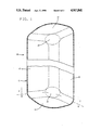
- FIG. 1 is a fragmentary perspective view of a portion of an upper corner and a lower corner of a refrigerator cabinet liner having each corner formed in accordance with the present invention
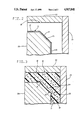
- FIG. 2 is a fragmentary sectional view of a portion of the liner of FIG. 1 taken along line 2--2 of FIG. 1 and an outer casing and showing the liner disposed in spaced relation to a foam plug and the outer casing prior to foaming of the foamed thermal insulation material;
- FIG. 3 is a fragmentary sectional view showing the formation of the corner of the liner of FIG. 2 after foaming of the foamed thermal insulation material is completed;
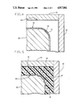
- FIG. 4 is a fragmentary sectional view of a corner of a refrigerator cabinet liner having a spherical radius and an outer casing and showing the liner disposed in spaced relation to a foam plug and the outer casing prior to foaming of the foamed thermal insulation material;
- FIG. 5 is a fragmentary sectional view showing formation of the corner of the liner of FIG. 4 after foaming of the foamed thermal insulation material is completed with the corner being crinkled.
- a refrigerator cabinet 10 including a liner 11 of a vacuum formed plastic.
- the liner 11 includes a rear wall 12, a side wall 13, and a bottom wall 14.
- the walls 12, 13, and 14 intersect to form a bottom corner 15 having a flat surface, as shown in FIG. 2, with the flat surface being formed with its periphery as a circle during vacuum forming of the liner 11.
- the liner 11 also has a top corner 16 formed at the intersection of the rear wall 12 and the side wall 13 with a top wall 17.
- the liner 11 also has a bottom corner (not shown) formed by the other side wall (not shown), the rear wall 12, and the bottom wall 14 and a top corner (not shown) formed by the other side wall, the rear wall 12, and the top wall 17.
- the refrigerator cabinet 10 includes an outer casing 18 and foamed thermal insulation material 19 between the outer casing 18 and the liner 11.
- foamed thermal insulation material 19 is to be foamed in place between the liner 11 and the outer casing 18, a foam plug 20 (see FIG. 2) of metal is positioned within the inner liner 11, which is open at the front.
- the foam plug 20 has a flat surface 21, which has its periphery as a circle, formed on the same angle as the angle of the bottom corner 15.
- the flat surface 21 of the foam plug 20 is substantially parallel to the flat surface of the bottom corner 15 prior to the thermal insulation material 19 (see FIG. 3) being foamed in place.
- the outer casing 18 (see FIG. 2) is positioned at a desired spacing from the liner 11 and retained in position by plates 22 and 23. With the plates 22 and 23 so positioned, a liquid foam material such as urethane, for example, is introduced into the space between the outer surface of the liner 11 and the inner surface of the outer casing 18.
- a pressure of 3-5 p.s.i. is created on the outer surface of the liner 11. This causes all of the surfaces of the liner 11 to move towards the corresponding surfaces of the foam plug 20.
- the bottom corner 15 is placed in tension so that a central circular portion 24 of the bottom corner 15 is moved against the flat surface 21 of the foam plug 20 to form the central portion 24 of the corner 15 with a slight convex shape in cross section as viewed in FIG. 3.
- This also produces an outer portion 25 of the bottom corner 15 surrounding the central portion 24 with the outer portion 25 having a concave shape in cross section as shown in FIG. 3.
- the outer portion 25 has its periphery formed as a circle.
- FIG. 4 there is shown a refrigerator cabinet liner 26, which is vacuum formed, with a bottom corner 27 having a spherical radius.
- a foam plug 28 has a similar spherical surface 29 for cooperating with the spherical radius of the bottom corner 27 when the foamed thermal insulation material 19 (see FIG. 5) is foamed in place between the liner 26 and the outer casing 18.
- the outer casing 18 has the plates 22 and 23 cooperating therewith in the same manner as discussed with respect to FIGS. 2 and 3.
- the refrigerator cabinet liner 26 or other structure having corners formed with a spherical radius will be crinkled at each corner when the range of the thickness of the liner varies from about 0.007" to 0.050".
- the maximum thickness of the liner 11 (see FIG. 1) at which this invention is used is that at which the liner 11 will not crinkle.
- a greater thickness of the liner 11 than 0.050" would require this invention to avoid a crinkled corner.
- An advantage of this invention is that it prevents crinkling at each corner of a vacuum formed structure such as a refrigerator cabinet liner, for example, of a relatively thin material. Another advantage of this invention is that it enables a relatively thin liner of a refrigerator cabinet to have an aesthetic appearance at each corner.
Abstract
Description
Claims (12)
Priority Applications (3)
| Application Number | Priority Date | Filing Date | Title |
|---|---|---|---|
| US07/254,732 US4917841A (en) | 1988-10-07 | 1988-10-07 | Method of making a refrigerator cabinet liner having non-crinkled corners |
| CA000602232A CA1318141C (en) | 1988-10-07 | 1989-06-08 | Refrigerator cabinet liner having non-crinkled corners and method of making |
| US07/642,564 US5033636A (en) | 1988-10-07 | 1991-01-18 | Refrigerator cabinet liner having non-crinkled corners |
Applications Claiming Priority (1)
| Application Number | Priority Date | Filing Date | Title |
|---|---|---|---|
| US07/254,732 US4917841A (en) | 1988-10-07 | 1988-10-07 | Method of making a refrigerator cabinet liner having non-crinkled corners |
Related Child Applications (1)
| Application Number | Title | Priority Date | Filing Date |
|---|---|---|---|
| US47520890A Division | 1988-10-07 | 1990-02-05 |
Publications (1)
| Publication Number | Publication Date |
|---|---|
| US4917841A true US4917841A (en) | 1990-04-17 |
Family
ID=22965376
Family Applications (1)
| Application Number | Title | Priority Date | Filing Date |
|---|---|---|---|
| US07/254,732 Expired - Lifetime US4917841A (en) | 1988-10-07 | 1988-10-07 | Method of making a refrigerator cabinet liner having non-crinkled corners |
Country Status (2)
| Country | Link |
|---|---|
| US (1) | US4917841A (en) |
| CA (1) | CA1318141C (en) |
Cited By (32)
| Publication number | Priority date | Publication date | Assignee | Title |
|---|---|---|---|---|
| FR2499865A1 (en) * | 1981-02-19 | 1982-08-20 | Saint Laumer Daniel De | Concn. and distn. plant - using compressor, evaporators, and condensers to replace fossil fuels |
| US5033636A (en) * | 1988-10-07 | 1991-07-23 | General Electric Company | Refrigerator cabinet liner having non-crinkled corners |
| US20040245666A1 (en) * | 2003-06-03 | 2004-12-09 | Tatung Co., Ltd. | Manufacturing method for a refrigerator door |
| US8944541B2 (en) | 2012-04-02 | 2015-02-03 | Whirlpool Corporation | Vacuum panel cabinet structure for a refrigerator |
| US9182158B2 (en) | 2013-03-15 | 2015-11-10 | Whirlpool Corporation | Dual cooling systems to minimize off-cycle migration loss in refrigerators with a vacuum insulated structure |
| US9221210B2 (en) | 2012-04-11 | 2015-12-29 | Whirlpool Corporation | Method to create vacuum insulated cabinets for refrigerators |
| US9599392B2 (en) | 2014-02-24 | 2017-03-21 | Whirlpool Corporation | Folding approach to create a 3D vacuum insulated door from 2D flat vacuum insulation panels |
| US9689604B2 (en) | 2014-02-24 | 2017-06-27 | Whirlpool Corporation | Multi-section core vacuum insulation panels with hybrid barrier film envelope |
| US9752818B2 (en) | 2015-12-22 | 2017-09-05 | Whirlpool Corporation | Umbilical for pass through in vacuum insulated refrigerator structures |
| US9840042B2 (en) | 2015-12-22 | 2017-12-12 | Whirlpool Corporation | Adhesively secured vacuum insulated panels for refrigerators |
| US10018406B2 (en) | 2015-12-28 | 2018-07-10 | Whirlpool Corporation | Multi-layer gas barrier materials for vacuum insulated structure |
| US10030905B2 (en) | 2015-12-29 | 2018-07-24 | Whirlpool Corporation | Method of fabricating a vacuum insulated appliance structure |
| US10041724B2 (en) | 2015-12-08 | 2018-08-07 | Whirlpool Corporation | Methods for dispensing and compacting insulation materials into a vacuum sealed structure |
| US10052819B2 (en) | 2014-02-24 | 2018-08-21 | Whirlpool Corporation | Vacuum packaged 3D vacuum insulated door structure and method therefor using a tooling fixture |
| US10161669B2 (en) | 2015-03-05 | 2018-12-25 | Whirlpool Corporation | Attachment arrangement for vacuum insulated door |
| US10222116B2 (en) | 2015-12-08 | 2019-03-05 | Whirlpool Corporation | Method and apparatus for forming a vacuum insulated structure for an appliance having a pressing mechanism incorporated within an insulation delivery system |
| US10345031B2 (en) | 2015-07-01 | 2019-07-09 | Whirlpool Corporation | Split hybrid insulation structure for an appliance |
| US10365030B2 (en) | 2015-03-02 | 2019-07-30 | Whirlpool Corporation | 3D vacuum panel and a folding approach to create the 3D vacuum panel from a 2D vacuum panel of non-uniform thickness |
| US10422569B2 (en) | 2015-12-21 | 2019-09-24 | Whirlpool Corporation | Vacuum insulated door construction |
| US10422573B2 (en) | 2015-12-08 | 2019-09-24 | Whirlpool Corporation | Insulation structure for an appliance having a uniformly mixed multi-component insulation material, and a method for even distribution of material combinations therein |
| US10429125B2 (en) | 2015-12-08 | 2019-10-01 | Whirlpool Corporation | Insulation structure for an appliance having a uniformly mixed multi-component insulation material, and a method for even distribution of material combinations therein |
| US10598424B2 (en) | 2016-12-02 | 2020-03-24 | Whirlpool Corporation | Hinge support assembly |
| US10610985B2 (en) | 2015-12-28 | 2020-04-07 | Whirlpool Corporation | Multilayer barrier materials with PVD or plasma coating for vacuum insulated structure |
| US10712080B2 (en) | 2016-04-15 | 2020-07-14 | Whirlpool Corporation | Vacuum insulated refrigerator cabinet |
| US10731915B2 (en) | 2015-03-11 | 2020-08-04 | Whirlpool Corporation | Self-contained pantry box system for insertion into an appliance |
| US10807298B2 (en) | 2015-12-29 | 2020-10-20 | Whirlpool Corporation | Molded gas barrier parts for vacuum insulated structure |
| US10907888B2 (en) | 2018-06-25 | 2021-02-02 | Whirlpool Corporation | Hybrid pigmented hot stitched color liner system |
| US11009284B2 (en) | 2016-04-15 | 2021-05-18 | Whirlpool Corporation | Vacuum insulated refrigerator structure with three dimensional characteristics |
| US11052579B2 (en) | 2015-12-08 | 2021-07-06 | Whirlpool Corporation | Method for preparing a densified insulation material for use in appliance insulated structure |
| US11247369B2 (en) | 2015-12-30 | 2022-02-15 | Whirlpool Corporation | Method of fabricating 3D vacuum insulated refrigerator structure having core material |
| US11320193B2 (en) | 2016-07-26 | 2022-05-03 | Whirlpool Corporation | Vacuum insulated structure trim breaker |
| US11391506B2 (en) | 2016-08-18 | 2022-07-19 | Whirlpool Corporation | Machine compartment for a vacuum insulated structure |
Citations (7)
| Publication number | Priority date | Publication date | Assignee | Title |
|---|---|---|---|---|
| US3122598A (en) * | 1960-11-03 | 1964-02-25 | Foster Grant Co Inc | Plastic decorating method |
| US3440308A (en) * | 1965-09-09 | 1969-04-22 | Gen Electric | Method of making a refrigerator cabinet assembly |
| US3911190A (en) * | 1974-12-23 | 1975-10-07 | Monsanto Co | Composite construction |
| US3944111A (en) * | 1974-11-04 | 1976-03-16 | Whirlpool Corporation | Freezer liner construction |
| US4535574A (en) * | 1981-11-06 | 1985-08-20 | Reich Spezialmaschinen Gmbh | Sanding tool and method of making such tool |
| US4676938A (en) * | 1986-01-15 | 1987-06-30 | John Brown, Inc. | Differential pressure thermoforming and foam injection process and apparatus |
| US4771532A (en) * | 1988-01-27 | 1988-09-20 | General Electric Company | Method of assembling a refrigerator |
-
1988
- 1988-10-07 US US07/254,732 patent/US4917841A/en not_active Expired - Lifetime
-
1989
- 1989-06-08 CA CA000602232A patent/CA1318141C/en not_active Expired - Fee Related
Patent Citations (7)
| Publication number | Priority date | Publication date | Assignee | Title |
|---|---|---|---|---|
| US3122598A (en) * | 1960-11-03 | 1964-02-25 | Foster Grant Co Inc | Plastic decorating method |
| US3440308A (en) * | 1965-09-09 | 1969-04-22 | Gen Electric | Method of making a refrigerator cabinet assembly |
| US3944111A (en) * | 1974-11-04 | 1976-03-16 | Whirlpool Corporation | Freezer liner construction |
| US3911190A (en) * | 1974-12-23 | 1975-10-07 | Monsanto Co | Composite construction |
| US4535574A (en) * | 1981-11-06 | 1985-08-20 | Reich Spezialmaschinen Gmbh | Sanding tool and method of making such tool |
| US4676938A (en) * | 1986-01-15 | 1987-06-30 | John Brown, Inc. | Differential pressure thermoforming and foam injection process and apparatus |
| US4771532A (en) * | 1988-01-27 | 1988-09-20 | General Electric Company | Method of assembling a refrigerator |
Cited By (56)
| Publication number | Priority date | Publication date | Assignee | Title |
|---|---|---|---|---|
| FR2499865A1 (en) * | 1981-02-19 | 1982-08-20 | Saint Laumer Daniel De | Concn. and distn. plant - using compressor, evaporators, and condensers to replace fossil fuels |
| US5033636A (en) * | 1988-10-07 | 1991-07-23 | General Electric Company | Refrigerator cabinet liner having non-crinkled corners |
| US20040245666A1 (en) * | 2003-06-03 | 2004-12-09 | Tatung Co., Ltd. | Manufacturing method for a refrigerator door |
| US6984349B2 (en) * | 2003-06-03 | 2006-01-10 | Tatung Co., Ltd. | Manufacturing method for a refrigerator door |
| US9874394B2 (en) | 2012-04-02 | 2018-01-23 | Whirlpool Corporation | Method of making a folded vacuum insulated structure |
| US10746458B2 (en) | 2012-04-02 | 2020-08-18 | Whirlpool Corporation | Method of making a folded vacuum insulated structure |
| US9038403B2 (en) | 2012-04-02 | 2015-05-26 | Whirlpool Corporation | Vacuum insulated door structure and method for the creation thereof |
| US9071907B2 (en) | 2012-04-02 | 2015-06-30 | Whirpool Corporation | Vacuum insulated structure tubular cabinet construction |
| US9140481B2 (en) | 2012-04-02 | 2015-09-22 | Whirlpool Corporation | Folded vacuum insulated structure |
| US8986483B2 (en) | 2012-04-02 | 2015-03-24 | Whirlpool Corporation | Method of making a folded vacuum insulated structure |
| US10663217B2 (en) | 2012-04-02 | 2020-05-26 | Whirlpool Corporation | Vacuum insulated structure tubular cabinet construction |
| US10697697B2 (en) | 2012-04-02 | 2020-06-30 | Whirlpool Corporation | Vacuum insulated door structure and method for the creation thereof |
| US9835369B2 (en) | 2012-04-02 | 2017-12-05 | Whirlpool Corporation | Vacuum insulated structure tubular cabinet construction |
| US8944541B2 (en) | 2012-04-02 | 2015-02-03 | Whirlpool Corporation | Vacuum panel cabinet structure for a refrigerator |
| US9885516B2 (en) | 2012-04-02 | 2018-02-06 | Whirlpool Corporation | Vacuum insulated door structure and method for the creation thereof |
| US10350817B2 (en) | 2012-04-11 | 2019-07-16 | Whirlpool Corporation | Method to create vacuum insulated cabinets for refrigerators |
| US9833942B2 (en) | 2012-04-11 | 2017-12-05 | Whirlpool Corporation | Method to create vacuum insulated cabinets for refrigerators |
| US9463917B2 (en) | 2012-04-11 | 2016-10-11 | Whirlpool Corporation | Method to create vacuum insulated cabinets for refrigerators |
| US9221210B2 (en) | 2012-04-11 | 2015-12-29 | Whirlpool Corporation | Method to create vacuum insulated cabinets for refrigerators |
| US9182158B2 (en) | 2013-03-15 | 2015-11-10 | Whirlpool Corporation | Dual cooling systems to minimize off-cycle migration loss in refrigerators with a vacuum insulated structure |
| US10105931B2 (en) | 2014-02-24 | 2018-10-23 | Whirlpool Corporation | Multi-section core vacuum insulation panels with hybrid barrier film envelope |
| US9689604B2 (en) | 2014-02-24 | 2017-06-27 | Whirlpool Corporation | Multi-section core vacuum insulation panels with hybrid barrier film envelope |
| US9599392B2 (en) | 2014-02-24 | 2017-03-21 | Whirlpool Corporation | Folding approach to create a 3D vacuum insulated door from 2D flat vacuum insulation panels |
| US10052819B2 (en) | 2014-02-24 | 2018-08-21 | Whirlpool Corporation | Vacuum packaged 3D vacuum insulated door structure and method therefor using a tooling fixture |
| US10365030B2 (en) | 2015-03-02 | 2019-07-30 | Whirlpool Corporation | 3D vacuum panel and a folding approach to create the 3D vacuum panel from a 2D vacuum panel of non-uniform thickness |
| US10161669B2 (en) | 2015-03-05 | 2018-12-25 | Whirlpool Corporation | Attachment arrangement for vacuum insulated door |
| US11713916B2 (en) | 2015-03-05 | 2023-08-01 | Whirlpool Corporation | Attachment arrangement for vacuum insulated door |
| US11243021B2 (en) | 2015-03-05 | 2022-02-08 | Whirlpool Corporation | Attachment arrangement for vacuum insulated door |
| US10731915B2 (en) | 2015-03-11 | 2020-08-04 | Whirlpool Corporation | Self-contained pantry box system for insertion into an appliance |
| US10345031B2 (en) | 2015-07-01 | 2019-07-09 | Whirlpool Corporation | Split hybrid insulation structure for an appliance |
| US10429125B2 (en) | 2015-12-08 | 2019-10-01 | Whirlpool Corporation | Insulation structure for an appliance having a uniformly mixed multi-component insulation material, and a method for even distribution of material combinations therein |
| US10222116B2 (en) | 2015-12-08 | 2019-03-05 | Whirlpool Corporation | Method and apparatus for forming a vacuum insulated structure for an appliance having a pressing mechanism incorporated within an insulation delivery system |
| US11691318B2 (en) | 2015-12-08 | 2023-07-04 | Whirlpool Corporation | Method for preparing a densified insulation material for use in appliance insulated structure |
| US10041724B2 (en) | 2015-12-08 | 2018-08-07 | Whirlpool Corporation | Methods for dispensing and compacting insulation materials into a vacuum sealed structure |
| US11052579B2 (en) | 2015-12-08 | 2021-07-06 | Whirlpool Corporation | Method for preparing a densified insulation material for use in appliance insulated structure |
| US10422573B2 (en) | 2015-12-08 | 2019-09-24 | Whirlpool Corporation | Insulation structure for an appliance having a uniformly mixed multi-component insulation material, and a method for even distribution of material combinations therein |
| US11009288B2 (en) | 2015-12-08 | 2021-05-18 | Whirlpool Corporation | Insulation structure for an appliance having a uniformly mixed multi-component insulation material, and a method for even distribution of material combinations therein |
| US10914505B2 (en) | 2015-12-21 | 2021-02-09 | Whirlpool Corporation | Vacuum insulated door construction |
| US10422569B2 (en) | 2015-12-21 | 2019-09-24 | Whirlpool Corporation | Vacuum insulated door construction |
| US9840042B2 (en) | 2015-12-22 | 2017-12-12 | Whirlpool Corporation | Adhesively secured vacuum insulated panels for refrigerators |
| US9752818B2 (en) | 2015-12-22 | 2017-09-05 | Whirlpool Corporation | Umbilical for pass through in vacuum insulated refrigerator structures |
| US10514198B2 (en) | 2015-12-28 | 2019-12-24 | Whirlpool Corporation | Multi-layer gas barrier materials for vacuum insulated structure |
| US10018406B2 (en) | 2015-12-28 | 2018-07-10 | Whirlpool Corporation | Multi-layer gas barrier materials for vacuum insulated structure |
| US10610985B2 (en) | 2015-12-28 | 2020-04-07 | Whirlpool Corporation | Multilayer barrier materials with PVD or plasma coating for vacuum insulated structure |
| US11577446B2 (en) | 2015-12-29 | 2023-02-14 | Whirlpool Corporation | Molded gas barrier parts for vacuum insulated structure |
| US10807298B2 (en) | 2015-12-29 | 2020-10-20 | Whirlpool Corporation | Molded gas barrier parts for vacuum insulated structure |
| US10030905B2 (en) | 2015-12-29 | 2018-07-24 | Whirlpool Corporation | Method of fabricating a vacuum insulated appliance structure |
| US11752669B2 (en) | 2015-12-30 | 2023-09-12 | Whirlpool Corporation | Method of fabricating 3D vacuum insulated refrigerator structure having core material |
| US11247369B2 (en) | 2015-12-30 | 2022-02-15 | Whirlpool Corporation | Method of fabricating 3D vacuum insulated refrigerator structure having core material |
| US10712080B2 (en) | 2016-04-15 | 2020-07-14 | Whirlpool Corporation | Vacuum insulated refrigerator cabinet |
| US11609037B2 (en) | 2016-04-15 | 2023-03-21 | Whirlpool Corporation | Vacuum insulated refrigerator structure with three dimensional characteristics |
| US11009284B2 (en) | 2016-04-15 | 2021-05-18 | Whirlpool Corporation | Vacuum insulated refrigerator structure with three dimensional characteristics |
| US11320193B2 (en) | 2016-07-26 | 2022-05-03 | Whirlpool Corporation | Vacuum insulated structure trim breaker |
| US11391506B2 (en) | 2016-08-18 | 2022-07-19 | Whirlpool Corporation | Machine compartment for a vacuum insulated structure |
| US10598424B2 (en) | 2016-12-02 | 2020-03-24 | Whirlpool Corporation | Hinge support assembly |
| US10907888B2 (en) | 2018-06-25 | 2021-02-02 | Whirlpool Corporation | Hybrid pigmented hot stitched color liner system |
Also Published As
| Publication number | Publication date |
|---|---|
| CA1318141C (en) | 1993-05-25 |
Similar Documents
| Publication | Publication Date | Title |
|---|---|---|
| US4917841A (en) | Method of making a refrigerator cabinet liner having non-crinkled corners | |
| US5033636A (en) | Refrigerator cabinet liner having non-crinkled corners | |
| US5384998A (en) | Curved panel | |
| US20050120540A1 (en) | Door device for vending machine | |
| US3857270A (en) | Method of shaping sheet material | |
| MXPA04006949A (en) | Corner piece for mattresses and the production method thereof. | |
| JP3341319B2 (en) | Refrigerator door | |
| US5400917A (en) | Box Construction and method | |
| US4323630A (en) | Trophy support column | |
| CN216001185U (en) | Inside filling device of cavity metal product | |
| JP2000161840A (en) | Heat insulating door | |
| JPS629942A (en) | Preparation of interior finishing material | |
| CA2227240A1 (en) | Moulded foam article with thick and thin wall portions | |
| JPH08117881A (en) | Production of external face panel of door using coated steel plate | |
| WO2022080369A1 (en) | Panel | |
| JP3982652B2 (en) | Synthetic resin reinforcing panel and synthetic resin casing using the synthetic resin reinforcing panel | |
| JPH01200184A (en) | Heat insulating door of refrigerator, etc. | |
| JP3598628B2 (en) | Manufacturing method of heat insulating material for heat insulating housing | |
| JP2002022348A (en) | Heat insulating door | |
| US4545687A (en) | Clock construction | |
| JPS5872408A (en) | Preparation of synthetic resin formed article | |
| JPS6215334B2 (en) | ||
| JPH023956Y2 (en) | ||
| JPS59230590A (en) | Seat body due to ultrasonic welding | |
| GB1275744A (en) | Improvements in or relating to refrigerator cabinets |
Legal Events
| Date | Code | Title | Description |
|---|---|---|---|
| AS | Assignment |
Owner name: GENERAL ELECTRIC COMPANY, A NEW YORK CORP. Free format text: ASSIGNMENT OF ASSIGNORS INTEREST.;ASSIGNOR:JENKINS, THOMAS E.;REEL/FRAME:004974/0006 Effective date: 19881004 |
|
| FEPP | Fee payment procedure |
Free format text: PAYOR NUMBER ASSIGNED (ORIGINAL EVENT CODE: ASPN); ENTITY STATUS OF PATENT OWNER: LARGE ENTITY |
|
| CC | Certificate of correction | ||
| REFU | Refund |
Free format text: REFUND OF EXCESS PAYMENTS PROCESSED (ORIGINAL EVENT CODE: R169); ENTITY STATUS OF PATENT OWNER: LARGE ENTITY |
|
| FEPP | Fee payment procedure |
Free format text: PAYER NUMBER DE-ASSIGNED (ORIGINAL EVENT CODE: RMPN); ENTITY STATUS OF PATENT OWNER: LARGE ENTITY Free format text: PAYOR NUMBER ASSIGNED (ORIGINAL EVENT CODE: ASPN); ENTITY STATUS OF PATENT OWNER: LARGE ENTITY |
|
| FPAY | Fee payment |
Year of fee payment: 4 |
|
| REFU | Refund |
Free format text: REFUND OF EXCESS PAYMENTS PROCESSED (ORIGINAL EVENT CODE: R169); ENTITY STATUS OF PATENT OWNER: LARGE ENTITY |
|
| FEPP | Fee payment procedure |
Free format text: PETITION RELATED TO MAINTENANCE FEES FILED (ORIGINAL EVENT CODE: PMFP); ENTITY STATUS OF PATENT OWNER: LARGE ENTITY |
|
| FEPP | Fee payment procedure |
Free format text: PETITION RELATED TO MAINTENANCE FEES GRANTED (ORIGINAL EVENT CODE: PMFG); ENTITY STATUS OF PATENT OWNER: LARGE ENTITY |
|
| REMI | Maintenance fee reminder mailed | ||
| FPAY | Fee payment |
Year of fee payment: 8 |
|
| SULP | Surcharge for late payment | ||
| FP | Lapsed due to failure to pay maintenance fee |
Effective date: 19980422 |
|
| PRDP | Patent reinstated due to the acceptance of a late maintenance fee |
Effective date: 19980925 |
|
| REMI | Maintenance fee reminder mailed | ||
| FEPP | Fee payment procedure |
Free format text: PETITION RELATED TO MAINTENANCE FEES FILED (ORIGINAL EVENT CODE: PMFP); ENTITY STATUS OF PATENT OWNER: LARGE ENTITY |
|
| FEPP | Fee payment procedure |
Free format text: PETITION RELATED TO MAINTENANCE FEES GRANTED (ORIGINAL EVENT CODE: PMFG); ENTITY STATUS OF PATENT OWNER: LARGE ENTITY |
|
| FPAY | Fee payment |
Year of fee payment: 12 |
|
| FP | Lapsed due to failure to pay maintenance fee |
Effective date: 20020417 |
|
| STCF | Information on status: patent grant |
Free format text: PATENTED CASE |
|
| SULP | Surcharge for late payment | ||
| PRDP | Patent reinstated due to the acceptance of a late maintenance fee |
Effective date: 20020617 |