US4917504A - Communications headset - Google Patents
Communications headset Download PDFInfo
- Publication number
- US4917504A US4917504A US07/348,052 US34805289A US4917504A US 4917504 A US4917504 A US 4917504A US 34805289 A US34805289 A US 34805289A US 4917504 A US4917504 A US 4917504A
- Authority
- US
- United States
- Prior art keywords
- housing
- ear
- ball
- socket joint
- wearer
- Prior art date
- Legal status (The legal status is an assumption and is not a legal conclusion. Google has not performed a legal analysis and makes no representation as to the accuracy of the status listed.)
- Expired - Lifetime
Links
Images


Classifications
-
- H—ELECTRICITY
- H04—ELECTRIC COMMUNICATION TECHNIQUE
- H04R—LOUDSPEAKERS, MICROPHONES, GRAMOPHONE PICK-UPS OR LIKE ACOUSTIC ELECTROMECHANICAL TRANSDUCERS; DEAF-AID SETS; PUBLIC ADDRESS SYSTEMS
- H04R1/00—Details of transducers, loudspeakers or microphones
- H04R1/10—Earpieces; Attachments therefor ; Earphones; Monophonic headphones
- H04R1/105—Earpiece supports, e.g. ear hooks
-
- H—ELECTRICITY
- H04—ELECTRIC COMMUNICATION TECHNIQUE
- H04M—TELEPHONIC COMMUNICATION
- H04M1/00—Substation equipment, e.g. for use by subscribers
- H04M1/02—Constructional features of telephone sets
- H04M1/04—Supports for telephone transmitters or receivers
- H04M1/05—Supports for telephone transmitters or receivers specially adapted for use on head, throat or breast
-
- H—ELECTRICITY
- H04—ELECTRIC COMMUNICATION TECHNIQUE
- H04R—LOUDSPEAKERS, MICROPHONES, GRAMOPHONE PICK-UPS OR LIKE ACOUSTIC ELECTROMECHANICAL TRANSDUCERS; DEAF-AID SETS; PUBLIC ADDRESS SYSTEMS
- H04R1/00—Details of transducers, loudspeakers or microphones
- H04R1/10—Earpieces; Attachments therefor ; Earphones; Monophonic headphones
- H04R1/1058—Manufacture or assembly
- H04R1/1066—Constructional aspects of the interconnection between earpiece and earpiece support
-
- H—ELECTRICITY
- H04—ELECTRIC COMMUNICATION TECHNIQUE
- H04R—LOUDSPEAKERS, MICROPHONES, GRAMOPHONE PICK-UPS OR LIKE ACOUSTIC ELECTROMECHANICAL TRANSDUCERS; DEAF-AID SETS; PUBLIC ADDRESS SYSTEMS
- H04R1/00—Details of transducers, loudspeakers or microphones
- H04R1/10—Earpieces; Attachments therefor ; Earphones; Monophonic headphones
- H04R1/1008—Earpieces of the supra-aural or circum-aural type
-
- H—ELECTRICITY
- H04—ELECTRIC COMMUNICATION TECHNIQUE
- H04R—LOUDSPEAKERS, MICROPHONES, GRAMOPHONE PICK-UPS OR LIKE ACOUSTIC ELECTROMECHANICAL TRANSDUCERS; DEAF-AID SETS; PUBLIC ADDRESS SYSTEMS
- H04R1/00—Details of transducers, loudspeakers or microphones
- H04R1/20—Arrangements for obtaining desired frequency or directional characteristics
- H04R1/32—Arrangements for obtaining desired frequency or directional characteristics for obtaining desired directional characteristic only
- H04R1/34—Arrangements for obtaining desired frequency or directional characteristics for obtaining desired directional characteristic only by using a single transducer with sound reflecting, diffracting, directing or guiding means
- H04R1/342—Arrangements for obtaining desired frequency or directional characteristics for obtaining desired directional characteristic only by using a single transducer with sound reflecting, diffracting, directing or guiding means for microphones
Definitions
- This invention relates generally to communications headsets, and more particularly to self-supporting, monaural headsets containing a microphone and a receiver.
- Communications headsets can be used in a diversity of applications, and are particularly effective for telephone operators, radio operators, aircraft personnel, and for other situations wherein it is desirable to support "hands free" access to communications systems. Accordingly, a wide variety of headsets have been known in the prior art.
- Known communications headsets can be broadly characterized on the basis of several fundamental aspects of their design and function, including: whether they deliver monaural or binaural sound; whether they are right-handed, left-handed or neither; whether they employ an invasive ear tip or a non-invasive loudspeaker in establishing a receiver-to-ear acoustical coupling; how they are physically supported on the user; their acoustical characteristics; and their economic qualities.
- headsets which deliver binaural sound may be neither right-handed nor left-handed, and may utilize some type of headband arrangement to secure receiver elements beside each ear.
- headbands have the disadvantages that they increase the size and weight of the headset, and tend to be uncomfortable or obtrusive to the user.
- Monaural headsets (having only a single receiver situated near one ear) may be quite compact, and therefore may not require the high stability of a headband. Uneven weight distribution can be a problem for monaural headsets, however, since the majority of the headset components are concentrated on one side of the head.
- Known self-supporting monaural headsets often rely on a molded ear tip inserted into the entrance of the auditory meatus for securing the device to the user.
- Such invasive eartips have the disadvantages of being uncomfortable and unhygenic.
- invasive eartips must conform closely to the geometry of a user's ear in order to be stable and secure, and are therefore typically either right-handed or left-handed only, and may not be optimally effective on all users.
- Ergonomic considerations in the design of communications headsets include the comfort of the device, the ease of putting the headset on and subsequently adjusting it for use, the restriction of user mobility resulting from the wearing of the headset, as well as the quality of sound delivered by the device.
- Acoustical qualities of communications headsets are often closely dependent on other aspects of the design. For example, the acoustical quality of the sound heard by a user is clearly affected by the nature of the receiver-to-ear seal. Invasive ear tips provide a good seal, but suffer from the aforementioned problems of comfort and hygiene. Non-invasive loudspeaker-type receivers, on the other hand, are more susceptible to acoustical degradation from background-level sound and attenuation of the acoustical wave passing through open space from the receiver to the auditory meatus.
- Another acoustical problem results from the arrangement and size of components in a headset.
- microphones and receivers of the smallest possible size and least weight, making the resulting headset as light and compact as possible.
- smaller components deliver a weaker acoustical signal, and must accordingly be closely coupled to the user.
- care must be taken, especially with miniaturized components in close proximity to each other, that the receiver(s), and transmitter of a headset be mechanically and acoustically decoupled.
- acoustic tubes within a headset to carry sound from its source to a transmitter or from a receiver to a user's auditory canal can subject the acoustical signals to undesirable resonance effects and other forms of interference, thus decreasing the overall frequency response and sound quality of the headset.
- a headset comprising two housings coupled by means of a swivel joint or a ball-and-socket joint, wherein one housing containing electronic circuitry and a microphone transducer is contoured to fit comfortably behind the ear and engage the ear generally at the top, while the second housing, which holds a miniature loudspeaker-type acoustical transducer, is adjusted at the coupling joint to a suitable position adjacent to the wearer's outer ear.
- a telescopically adjustable flexible voice pick-up tube originates generally near the top of the first housing and is easily adjusted so that its distal end is situated in close proximity to the wearer's mouth.
- the microphone can be disposed at the end of a support boom coupled to the first housing, eliminating the need for a voice pick-up tube to carry acoustical signals to a microphone in the first housing.
- FIG. 1 is an illustration of a headset in accordance with one embodiment of the present invention
- FIG. 2 is an illustration of one housing of the headset of FIG. 1 depicting its contoured shape
- FIG. 3 is an enlarged illustration of both housings of the headset of FIG. 1;
- FIGS. 4a, 4b, and 4 c are illustrations of a ball-and-socket joint coupling the housings of FIGS. 1 and 3;
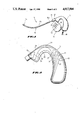
- FIGS. 5a and 5b are illustrations of the headset of FIG. 1 being worn on a user's right ear.
- FIGS. 6a, 6b and 6c are illustrations showing the adjustment capabilities of the headset of FIG. 1.
- Headset 10 comprises a first molded housing 12, a second molded receiver housing 14 coupled to first molded housing 12 in a manner hereinafter described, a telescoping voice pick-up tube 16 originating generally near the top of first molded housing 12, and an electrical cable 18 originating generally near the bottom of first molded housing 12.
- Voice pick-up tube 16 includes telescoping portions 16a and 16b allowing tube 16 to be extended or retracted such that the distal end 16c of pick-up tube 16 may be positioned adjacent to a wearer's mouth.
- Tube portion 16a is preferably made of a plastic, or another suitably flexible and lightweight material, while tube portion 16b is made of stainless steel or another suitably rigid material for facilitating a sufficiently tight frictional seal with a flanged end 16d of flexible tube 16a.
- Rigid tube 16b is detachably coupled to housing 12 by means of a ferrule 20.
- tube 16b is secured to housing 12 through slots in the sides of ferrule 20 which releasably engage a pair of pins 22 mounted in and extending radially from a cylindrical protrusion 21 of housing 12. Pins 22 are more clearly shown in FIG. 2.
- Ferrule 20 is of a conventional structure well known in the art to allow for angular adjustment of pick-up tube 16.
- Housing 12 may comprise two mating parts which are affixed to one another as, for example, by pins, sonic bonding, or the like. When assembled, housing 12 is contoured to fit snugly but comfortably behind the ear of a user. Referring to FIG. 2, a contour diagram of housing 12 is shown. Contour line C1 indicates the region of housing 12 having a thickness of approximately 0.4 inches; contour line C2 indicates the region of housing 12 having a thickness of approximately 0.36 inches. Housing 12 has a thickness of about 0.32 inches at contour line C3, 0.28 inches at line C4, and 0.26 inches at line C5.
- housing 12 has a thickness of approximately 0.24 inches, at line C8 a thickness of approximately 0.2 inches, and at line C9 a thickness of approximately 0.16 inches. It should be noted that the contour lines C1 through C9 of FIG. 2 are meant to indicate only generally the thickness of housing 12, and not to indicate boundaries of transition between one thickness and another; housing 12 is smoothly formed from molded ABS or the like, as previously described, and its surfaces are generally devoid of sharp or highly angular edges which could cause discomfort to a wearer.
- housings 12 and 14 are shown with one side of each housing 12, 14 removed to expose internal elements.
- the contents of housing 12 include a microphone transducer 24 and a printed circuit board 26.
- Microphone 24 is acoustically coupled to rigid portion 16b of voice tube 16 via connecting tube 28, which meets an end of rigid voice tube 16b within ferrule 20.
- the coupling of connecting tube 28 with rigid voice tube 16b occurs generally within ferrule 20.
- ferrule 20 releasably engages housing 12 by means of pins 22.
- Connecting tube 28, microphone 24, and printed circuit board 26 are each supported within housing 12 by means of appropriately formed support struts 30, which struts 30 are preferably integral internal features that may be formed during the molding process of housing 12.
- receiver housing 14 contains a loudspeaker-type receiver transducer 46.
- Housing 14, like housing 12, is preferably constructed from two mating halves; in order to expose internal components of the receiver, one half of housing 14 is not shown in FIG. 3.
- each half of housing 14 provided with acoustical port holes 32 on its substantially planar face, for allowing sound produced by receiver transducer 46 to exit receiver housing 14 and be audible to a person wearing headset 10 on either the right or left ear.
- Receiver housing 14 is coupled to housing 12 by means of a joint designated generally as 34, adapted to allow for adjustment of receiver housing 14 with respect to housing 12.
- a ball-and-socket joint 34 is preferred, but a swivel joint could be used.
- FIG. 4a An enlarged view of ball-and-socket joint 34 is shown in FIG. 4a.
- Tubular mounting beam 36 is rigidly supported within housing 12 by support struts 30.
- a circular collar 35 around a portion of beam 36 in housing 12 is received between supports 30, functioning to increase the stability of joint 34.
- collar 35 can serve to increase the frictional resistance to this rotation, so that the headset tends to remain in its adjusted position during use.
- a cap 37 is dispose on the end of beam 36 in housing 12 to prevent beam 36 from sliding axially out of housing 12.
- beam 36 may be provided with a flared end to achieve the same result.
- beam 36 enters housing 14 via a hole 40 therein.
- the inner diameter of hole 40 is larger than the outer diameter of tubular mounting beam 36, creating gaps 39 between housing 14 and beam 36.
- Formed around the end of beam 36 in housing 14 is a ball 38 which is frictionally supported within a cavity 41.
- ball-and-socket joint 34 allows for angular and rotary motion of housing 14 in all directions with respect to tubular beam 36. This motion is limited, however, by the size of gaps 39 between beam 36 and housing 14.
- beam 36 is shown in two extreme positions, with the total allowable angle of adjustment (in the X-Y plane of FIG. 4b) being designated by.
- Tubular beam 36, collar 35, ball 38 and cap 37 are shown in greater detail in FIG. 4c.
- receiver wires 42 enter housing 12 through ball-and-socket joint 34 and tubular beam 36, as previously described. Receiver wires 42 travel generally adjacent to connecting tube 28, continuing past microphone 24 and printed circuit board 26, where the wires 42 are combined with other wires originating on printed circuit board 26 to form the electrical cable 18. Support struts 30 generally define a path for receiver wires 42, so that the wires 42 do not interfere with other components within housing 12. Electrical cable 18 is secured to housing 12 by means of a resilient strain relief collar 44, which frictionally prevents cable 18 from being forcibly withdrawn from housing 12.
- headset 10 of the present invention is equally suitable for wearing on either the right of left ear.
- This capability is further facilitated by the provision of acoustical port holes 32 on both substantially planar faces of receiver housing 14, as well as by the ball-and-socket joint 34 coupling housing 12 to housing 14 and allowing for the adjustment of receiver housing 12 to lie adjacent to either a right or left ear.
- FIG. 5a an illustration of a headset in accordance with the present invention being worn on the right ear of a wearer is shown.
- a portion of housing 12 is hidden from view in FIG. 5, behind the auricle 50 of the wearer's ear, as indicated by the dashed line 52.
- the forwardly-directed portion of housing 12 including cylindrical protrusion 21 extends slightly in front of the ear, not covered by auricle 50. With housing 12 in this position, cylindrical protrusion 21 is directed forward and down, generally in the direction of the wearer's mouth.
- Receiver housing 14 rests in front of the external acoustic meatus of the ear, coupled to housing 12 by means of ball-and-socket joint 34. While a conventional swiveling connection, such as a stationary shaft or pin could be employed to couple housing 14 to housing 12, a ball-and-socket joint is preferred due to the increased freedom of adjustment which it affords.
- line 66 is tangent to housing 14 at the arbitrarily chosen point 68, and is fixed with respect to housing 14.
- Line 70 indicates the direction in which tubular mounting beam 36 extends from housing 12, along the central plane of housing 12.
- Line 71 which also lies in the central plane of housing 12, is perpendicular to line 70. Since line 66 is fixed with respect to housing 14, and line 70 (the axis of tubular mounting beam 36) is fixed with respect to housing 12, the angle between lines 66 and 70 is representative of the relative positions of housings 12 and 14, in the two-dimensional plane defined by the central plane of housing 12.
- Ball-and-socket joint 34 permits housing 14 to be moved in several directions with respect to housing 12.
- the circular movement indicated by arrows 72 and 73 allows receiver housing 14 to be moved generally forward and down (arrow 72) or aft and up (arrow 73) with respect to the wearer's head. This facilitates adaptation of housing 14 to the varying heights and widths of different wearers' ears.
- ball-and-socket joint 34 permits housing 12 to be rotated about the axis defined by by tubular mounting beam 36 in joint 34 (the axis designated as 70), as indicated by arrows 74; this permits receiver housing 14 to be folded into a position in which it rests lightly against the outer surfaces of the wearer's auricle.
- ball-and-socket joint 34 permits rotation of housing 14 about line 71, as indicated by arrows 76; again, this permits comfortable use by different wearers having various auricular geometries.
- the shape of the forwardly-directed portion of housing 12 and positioning of cylindrical protrusion 21 functions to restrict the range of movement of housing 14. Recall from FIG. 3 that receiver wires 42 pass through tubular mounting beam 36 from housing 12 to housing 14, to be received by receiver transducer 46. Cylindrical protrusion 21 limits the rotational motion of housing 14 indicated by arrows 74 in FIG. 5b to less than 360. This limitation is crucial, since it prevents receiver wires 42 from being subjected to excessive stress and repeated over-twisting, possibly leading to wire fatigue or loosened electrical connections.
- housing 14 The limited rotation of housing 14 around axis 70 is more clearly illustrated in FIG. 6a, in which housing 14 and cylindrical protrusion 21 are shown from a line of sight along the axis 70 of cylindrical beam 36.
- housing 14 is shown in two positions corresponding to the extreme points of rotation about axis 70.
- the arc of rotation designated by the line 78 is less than 360.
- FIGS. 6b and 6c are similar axial views of housings 12 and 14 showing the typical relative positions of these housings while headset 10 is being worn on the right and left ears, respectively, of a wearer.
- acoustical signals produced by receiver 46 in housing 14 travel in the direction indicated by arrow 80 to be heard by the wearer; in FIG. 6c, sound heard by the wearer travels in the direction shown by arrow 82. Since the rotation of housing 14 about axis 70 is limited to less than a complete rotation, it is necessary for acoustical signals to be emitted from both planar faces of housing 14, in the directions indicated by arrows 80 and 82 in FIGS. 6b and 6c.
- acoustical port holes 32 are provided on both sides of housing 14. Acoustical port holes 32 must be of sufficient size to allow sound to be emitted from housing 14 without undue acoustical degradation.
- a lightweight, monaural communications headset which is capable of being worn on either the right or left ear of a user.
- an alternate embodiment of the present invention which utilizes a "boom mounted" microphone arrangement.
- a miniature microphone transducer is disposed at the distal end of an adjustable boom originating on the post-auricular headset capsule housing.
- a swiveling or pivoting connection between the boom and the housing allows the microphone to be positioned in front of the wearer's mouth, when the headset is worn on the right and when it is worn on the left ear.
- Microphone wires are conducted through the boom and are received on the printed circuit board contained in the post-auricular housing.
Abstract
A lightweight, monaural communications headset is disclosed which is readily adjustable to be worn on either the right or left ear of a wearer. The disclosed headset consists of two housings, one for holding electronic circuitry for the headset, and the other for holding an acoustical transmitter. The two housings are coupled with a swivel or ball-and-socket coupling, so that the device may be positioned behind either the right or left ear of a wearer. The transmitter housing is provided with acoustical port holes on both of its sides to further facilitate the reversible wearing of the device. The disclosed headset is constructed from lightweight materials so that it is self-supporting, and causes minimal discomfort to the wearer.
Description
This invention relates generally to communications headsets, and more particularly to self-supporting, monaural headsets containing a microphone and a receiver.
Communications headsets can be used in a diversity of applications, and are particularly effective for telephone operators, radio operators, aircraft personnel, and for other situations wherein it is desirable to support "hands free" access to communications systems. Accordingly, a wide variety of headsets have been known in the prior art.
Known communications headsets can be broadly characterized on the basis of several fundamental aspects of their design and function, including: whether they deliver monaural or binaural sound; whether they are right-handed, left-handed or neither; whether they employ an invasive ear tip or a non-invasive loudspeaker in establishing a receiver-to-ear acoustical coupling; how they are physically supported on the user; their acoustical characteristics; and their economic qualities.
Typically in the art, headsets which deliver binaural sound (i.e. ones which have acoustical transducers for both ears) may be neither right-handed nor left-handed, and may utilize some type of headband arrangement to secure receiver elements beside each ear. Although generally providing very stable support for the headset, headbands have the disadvantages that they increase the size and weight of the headset, and tend to be uncomfortable or obtrusive to the user.
Monaural headsets (having only a single receiver situated near one ear) may be quite compact, and therefore may not require the high stability of a headband. Uneven weight distribution can be a problem for monaural headsets, however, since the majority of the headset components are concentrated on one side of the head. Known self-supporting monaural headsets often rely on a molded ear tip inserted into the entrance of the auditory meatus for securing the device to the user. Such invasive eartips have the disadvantages of being uncomfortable and unhygenic. In addition, invasive eartips must conform closely to the geometry of a user's ear in order to be stable and secure, and are therefore typically either right-handed or left-handed only, and may not be optimally effective on all users.
Ergonomic considerations in the design of communications headsets include the comfort of the device, the ease of putting the headset on and subsequently adjusting it for use, the restriction of user mobility resulting from the wearing of the headset, as well as the quality of sound delivered by the device.
Acoustical qualities of communications headsets are often closely dependent on other aspects of the design. For example, the acoustical quality of the sound heard by a user is clearly affected by the nature of the receiver-to-ear seal. Invasive ear tips provide a good seal, but suffer from the aforementioned problems of comfort and hygiene. Non-invasive loudspeaker-type receivers, on the other hand, are more susceptible to acoustical degradation from background-level sound and attenuation of the acoustical wave passing through open space from the receiver to the auditory meatus.
Another acoustical problem results from the arrangement and size of components in a headset. Naturally, it is desirable to utilize microphones and receivers of the smallest possible size and least weight, making the resulting headset as light and compact as possible. Typically, however, smaller components deliver a weaker acoustical signal, and must accordingly be closely coupled to the user. In addition, care must be taken, especially with miniaturized components in close proximity to each other, that the receiver(s), and transmitter of a headset be mechanically and acoustically decoupled. Lastly, the use of acoustic tubes within a headset to carry sound from its source to a transmitter or from a receiver to a user's auditory canal can subject the acoustical signals to undesirable resonance effects and other forms of interference, thus decreasing the overall frequency response and sound quality of the headset.
It is a general feature of the present invention to provide a lightweight, self-supporting headset which can be comfortably and securely fitted to a wide range of users without undue individual attention.
It is a further feature of the present invention to provide a headset which is shaped and constructed to be worn comfortably and stably behind the ear of a wearer.
It is still another feature of the present invention that a satisfactory receiver-to-ear coupling is established with a wearer's left or right ear with equal ease, and without the use of an invasive ear tip.
In general, the foregoing and other features are achieved, in accordance with the present invention, with a headset comprising two housings coupled by means of a swivel joint or a ball-and-socket joint, wherein one housing containing electronic circuitry and a microphone transducer is contoured to fit comfortably behind the ear and engage the ear generally at the top, while the second housing, which holds a miniature loudspeaker-type acoustical transducer, is adjusted at the coupling joint to a suitable position adjacent to the wearer's outer ear. A telescopically adjustable flexible voice pick-up tube originates generally near the top of the first housing and is easily adjusted so that its distal end is situated in close proximity to the wearer's mouth.
In the alternative, the microphone can be disposed at the end of a support boom coupled to the first housing, eliminating the need for a voice pick-up tube to carry acoustical signals to a microphone in the first housing.
The novel features believed characteristic of a headset of the present invention are set forth in the appended claims. The invention itself, however, as well as other features and advantages thereof, will be best understood by reference to a detailed description of a specific embodiment which follows, when read in conjunction with, the accompanying drawings, wherein: accordance with one embodiment of the present invention;
FIG. 1 is an illustration of a headset in accordance with one embodiment of the present invention;
FIG. 2 is an illustration of one housing of the headset of FIG. 1 depicting its contoured shape;
FIG. 3 is an enlarged illustration of both housings of the headset of FIG. 1; and
FIGS. 4a, 4b, and 4 c are illustrations of a ball-and-socket joint coupling the housings of FIGS. 1 and 3;
FIGS. 5a and 5b are illustrations of the headset of FIG. 1 being worn on a user's right ear; and
FIGS. 6a, 6b and 6c are illustrations showing the adjustment capabilities of the headset of FIG. 1.
Referring to FIG. 1, a headset in accordance with one embodiment of the present invention is illustrated, designated generally as 10. Headset 10 comprises a first molded housing 12, a second molded receiver housing 14 coupled to first molded housing 12 in a manner hereinafter described, a telescoping voice pick-up tube 16 originating generally near the top of first molded housing 12, and an electrical cable 18 originating generally near the bottom of first molded housing 12. Voice pick-up tube 16 includes telescoping portions 16a and 16b allowing tube 16 to be extended or retracted such that the distal end 16c of pick-up tube 16 may be positioned adjacent to a wearer's mouth. Tube portion 16a is preferably made of a plastic, or another suitably flexible and lightweight material, while tube portion 16b is made of stainless steel or another suitably rigid material for facilitating a sufficiently tight frictional seal with a flanged end 16d of flexible tube 16a. Rigid tube 16b is detachably coupled to housing 12 by means of a ferrule 20. In particular, tube 16b is secured to housing 12 through slots in the sides of ferrule 20 which releasably engage a pair of pins 22 mounted in and extending radially from a cylindrical protrusion 21 of housing 12. Pins 22 are more clearly shown in FIG. 2. Ferrule 20 is of a conventional structure well known in the art to allow for angular adjustment of pick-up tube 16.
Referring now to FIG. 3, a greatly enlarged view of housings 12 and 14 is shown with one side of each housing 12, 14 removed to expose internal elements. The contents of housing 12 include a microphone transducer 24 and a printed circuit board 26. Microphone 24 is acoustically coupled to rigid portion 16b of voice tube 16 via connecting tube 28, which meets an end of rigid voice tube 16b within ferrule 20. The coupling of connecting tube 28 with rigid voice tube 16b occurs generally within ferrule 20. As previously noted, ferrule 20 releasably engages housing 12 by means of pins 22. Connecting tube 28, microphone 24, and printed circuit board 26 are each supported within housing 12 by means of appropriately formed support struts 30, which struts 30 are preferably integral internal features that may be formed during the molding process of housing 12.
With continued reference to FIG. 3, receiver housing 14 contains a loudspeaker-type receiver transducer 46. Housing 14, like housing 12, is preferably constructed from two mating halves; in order to expose internal components of the receiver, one half of housing 14 is not shown in FIG. 3. As indicated in FIG. 1, each half of housing 14 provided with acoustical port holes 32 on its substantially planar face, for allowing sound produced by receiver transducer 46 to exit receiver housing 14 and be audible to a person wearing headset 10 on either the right or left ear. Receiver housing 14 is coupled to housing 12 by means of a joint designated generally as 34, adapted to allow for adjustment of receiver housing 14 with respect to housing 12. A ball-and-socket joint 34 is preferred, but a swivel joint could be used. An enlarged view of ball-and-socket joint 34 is shown in FIG. 4a. Tubular mounting beam 36 is rigidly supported within housing 12 by support struts 30. A circular collar 35 around a portion of beam 36 in housing 12 is received between supports 30, functioning to increase the stability of joint 34. Although tubular beam 36 is free to rotate in place within housing 12, collar 35 can serve to increase the frictional resistance to this rotation, so that the headset tends to remain in its adjusted position during use. A cap 37 is dispose on the end of beam 36 in housing 12 to prevent beam 36 from sliding axially out of housing 12. As an alternative to cap 37, beam 36 may be provided with a flared end to achieve the same result.
With continued reference to FIG. 4a, beam 36 enters housing 14 via a hole 40 therein. The inner diameter of hole 40 is larger than the outer diameter of tubular mounting beam 36, creating gaps 39 between housing 14 and beam 36. Formed around the end of beam 36 in housing 14 is a ball 38 which is frictionally supported within a cavity 41.
As shown in FIG. 4b, ball-and-socket joint 34 allows for angular and rotary motion of housing 14 in all directions with respect to tubular beam 36. This motion is limited, however, by the size of gaps 39 between beam 36 and housing 14. In FIG. 4b, beam 36 is shown in two extreme positions, with the total allowable angle of adjustment (in the X-Y plane of FIG. 4b) being designated by.
Referring again to FIG. 3, receiver wires 42 enter housing 12 through ball-and-socket joint 34 and tubular beam 36, as previously described. Receiver wires 42 travel generally adjacent to connecting tube 28, continuing past microphone 24 and printed circuit board 26, where the wires 42 are combined with other wires originating on printed circuit board 26 to form the electrical cable 18. Support struts 30 generally define a path for receiver wires 42, so that the wires 42 do not interfere with other components within housing 12. Electrical cable 18 is secured to housing 12 by means of a resilient strain relief collar 44, which frictionally prevents cable 18 from being forcibly withdrawn from housing 12.
Due to the symmetrical design of housings 12 and 14, headset 10 of the present invention is equally suitable for wearing on either the right of left ear. This capability is further facilitated by the provision of acoustical port holes 32 on both substantially planar faces of receiver housing 14, as well as by the ball-and-socket joint 34 coupling housing 12 to housing 14 and allowing for the adjustment of receiver housing 12 to lie adjacent to either a right or left ear.
In FIG. 5a, an illustration of a headset in accordance with the present invention being worn on the right ear of a wearer is shown. A portion of housing 12 is hidden from view in FIG. 5, behind the auricle 50 of the wearer's ear, as indicated by the dashed line 52. The forwardly-directed portion of housing 12 including cylindrical protrusion 21 extends slightly in front of the ear, not covered by auricle 50. With housing 12 in this position, cylindrical protrusion 21 is directed forward and down, generally in the direction of the wearer's mouth.
In FIG. 5b, line 66 is tangent to housing 14 at the arbitrarily chosen point 68, and is fixed with respect to housing 14. Line 70 indicates the direction in which tubular mounting beam 36 extends from housing 12, along the central plane of housing 12. Line 71, which also lies in the central plane of housing 12, is perpendicular to line 70. Since line 66 is fixed with respect to housing 14, and line 70 (the axis of tubular mounting beam 36) is fixed with respect to housing 12, the angle between lines 66 and 70 is representative of the relative positions of housings 12 and 14, in the two-dimensional plane defined by the central plane of housing 12.
Ball-and-socket joint 34 permits housing 14 to be moved in several directions with respect to housing 12. In particular, the circular movement indicated by arrows 72 and 73 allows receiver housing 14 to be moved generally forward and down (arrow 72) or aft and up (arrow 73) with respect to the wearer's head. This facilitates adaptation of housing 14 to the varying heights and widths of different wearers' ears. Furthermore, ball-and-socket joint 34 permits housing 12 to be rotated about the axis defined by by tubular mounting beam 36 in joint 34 (the axis designated as 70), as indicated by arrows 74; this permits receiver housing 14 to be folded into a position in which it rests lightly against the outer surfaces of the wearer's auricle. Lastly, ball-and-socket joint 34 permits rotation of housing 14 about line 71, as indicated by arrows 76; again, this permits comfortable use by different wearers having various auricular geometries.
In accordance with a further aspect of this embodiment of the invention, the shape of the forwardly-directed portion of housing 12 and positioning of cylindrical protrusion 21 functions to restrict the range of movement of housing 14. Recall from FIG. 3 that receiver wires 42 pass through tubular mounting beam 36 from housing 12 to housing 14, to be received by receiver transducer 46. Cylindrical protrusion 21 limits the rotational motion of housing 14 indicated by arrows 74 in FIG. 5b to less than 360. This limitation is crucial, since it prevents receiver wires 42 from being subjected to excessive stress and repeated over-twisting, possibly leading to wire fatigue or loosened electrical connections.
The limited rotation of housing 14 around axis 70 is more clearly illustrated in FIG. 6a, in which housing 14 and cylindrical protrusion 21 are shown from a line of sight along the axis 70 of cylindrical beam 36. In FIG. 6a, housing 14 is shown in two positions corresponding to the extreme points of rotation about axis 70. Clearly, the arc of rotation designated by the line 78 is less than 360.
FIGS. 6b and 6c are similar axial views of housings 12 and 14 showing the typical relative positions of these housings while headset 10 is being worn on the right and left ears, respectively, of a wearer. In FIG. 6b, acoustical signals produced by receiver 46 in housing 14 travel in the direction indicated by arrow 80 to be heard by the wearer; in FIG. 6c, sound heard by the wearer travels in the direction shown by arrow 82. Since the rotation of housing 14 about axis 70 is limited to less than a complete rotation, it is necessary for acoustical signals to be emitted from both planar faces of housing 14, in the directions indicated by arrows 80 and 82 in FIGS. 6b and 6c. Accordingly, and in keeping with the overall symmetry of housings 12 and 14, acoustical port holes 32, such as are shown in FIG. 1, are provided on both sides of housing 14. Acoustical port holes 32 must be of sufficient size to allow sound to be emitted from housing 14 without undue acoustical degradation.
From the above detailed description of a specific embodiment, it should be evident that a lightweight, monaural communications headset has been disclosed which is capable of being worn on either the right or left ear of a user.
Although a specific embodiment has been disclosed in detail, it is to be understood that various changes, alterations and substitutions can be made therein without departing from the spirit and scope of the present invention as defined in the appended claims. For example, an alternate embodiment of the present invention is contemplated which utilizes a "boom mounted" microphone arrangement. In this case, a miniature microphone transducer is disposed at the distal end of an adjustable boom originating on the post-auricular headset capsule housing. A swiveling or pivoting connection between the boom and the housing allows the microphone to be positioned in front of the wearer's mouth, when the headset is worn on the right and when it is worn on the left ear. Microphone wires are conducted through the boom and are received on the printed circuit board contained in the post-auricular housing.
Claims (4)
1. A communications headset comprising:
a first housing containing a microphone transducer and electronic circuitry, the first housing being symmetrical about a central plane and having a substantially hook-shaped outline in its central plane, such that said housing can be lowered into a secure, post-auricular position, the interior curve of said hook shape engaging the wearer's ear and securing said housing behind the auricle, around the rear and top of the ear, with a forwardly-directed portion of the first housing extending partially in front of the ear, said forwardly-directed portion having a cylindrical protrusion extending therefrom;
a second housing, symmetrical about a central plane and having a substantially teardrop-shaped outline in its central plane, containing an acoustical receiver having wires coupled thereto, the second housing having acoustical port holes on both of its substantially planar and teardrop-shaped outer surfaces and being coupled near its apex to said forwardly-directed portion of the first housing with a ball-and-socket joint which allows limited angular and rotary movement of the second housing with respect to the first housing such that the second housing may be folded inwardly to a position substantially parallel with the external surfaces of the wearer's ear, the ball-and-socket joint also permitting rotation of the second housing about the axis of the ball-and-socket joint, the extent of said rotation being limited by the cylindrical protrusion on said forwardly-extending portion of the first housing, the ball-and-socket joint further defining a hollow channel between the first and second housings through which said receiver wires pass; and
a flexible, telescoping voice tube having proximal and distal ends, the proximal end detachably coupled to said cylindrical protrusion on the forwardly-directed portion of the first housing, said voice tube extending forward and down from the first housing such that the distal end can be positioned generally in front of the wearer's mouth.
2. A communications headset apparatus comprising:
a first housing, symmetrical about a central plane and having a substantially hook-shaped outline in said plane, for containing a microphone transducer and electronic circuitry, said hook-shape allowing the first housing to be worn in a conventional post-auricular manner with the first housing originating aft of a wearers ear, curving over the top of the ear, and extending partially forward of the ear;
a second housing, symmetrical about a central plane and having a substantially teardrop-shaped outline in its central plane, for containing an acoustical receiver having wires coupled thereto, the second housing having acoustical port holes on both of its substantially planar, teardrop-shaped surfaces;
a ball-and-socket joint, for coupling an edge of said second housing near its apex to the forwardly extending portion of the first housing, the ball-and-socket joint allowing angular and rotary motion of the second housing in every direction with respect to the first housing within certain limits, the ball-and-socket joint defining a hollow channel between the first and second housings through which said receiver wires may pass; and
a flexible, telescoping voice pick-up tube having proximal and distal ends, the proximal end detachably coupled to a cylindrical protrusion on said forwardly extending portion of the first housing, and the distal end positionable generally in front of the wearer's mouth, said protrusion preventing the complete rotation of the second housing about the axis of the ball-and-socket connection.
3. A communications headset comprising:
a first housing containing electronic circuitry, the first housing being symmetrical about a central plane and having a substantially hook-shaped outline in said central plane, such that said housing can be lowered into a secure, post-auricular position, an interior curve of said hook shape engaging the wearer's ear and securing said housing behind the auricle, around the rear and top of the ear, with a forwardly-directed portion of the first housing extending partially in front of the ear;
a second housing, symmetrical about a central plane and having a substantially teardrop-shaped outline in its central plane, containing an acoustical receiver having wires coupled thereto, the second housing having acoustical port holes on both of its substantially planar and teardrop-shaped outer surfaces and being coupled near its apex to said forwardly-directed portion of the first housing with a ball-and-socket joint which allows limited angular and rotary movement of the second housing with respect to the first housing such that the second housing may be folded inwardly to a position substantially parallel with the external surfaces of the wearer's ear, the ball-and-socket joint also permitting rotation of the second housing about the axis of the ball-and-socket joint, the extent of said rotation being physically constrained within limits defined by the shape of said forwardly-directed portion of the first housing, the ball-and-socket joint further defining a hollow channel between the first and second housings through which said receiver wires may pass; and
a microphone electrically coupled to said electronic circuitry, for converting the wearer's speech into electrical signals.
4. A communications headset apparatus comprising:
a first housing, symmetrical about a central plane and having a substantially hook-shaped outline in said plane, for containing electronic circuitry, said hook-shape allowing the first housing to be worn in a conventional post-auricular manner with the first housing originating aft of a wearer's ear, curving over the top of the ear, and extending partially forward of the ear;
a second housing, symmetrical about a central plane and having a substantially teardrop-shaped outline in its central plane, for containing an acoustical receiver having wires coupled thereto, the second housing having acoustical port holes on both of its substantially planar, teardrop-shaped surfaces;
a ball-and-socket joint, for coupling an edge of said second housing near its apex to the forwardly extending portion of the first housing, the ball-and-socket joint allowing angular and rotary motion of the second housing with respect to the first housing within certain limits defined by the shape of the forwardly-extending portion of the first housing, the ball-and-socket joint defining a hollow channel between the first and second housings through which said receiver wires may pass; and
a microphone electrically coupled to said electronic circuitry, for converting the wearer's speech into electrical signals.
Priority Applications (9)
| Application Number | Priority Date | Filing Date | Title |
|---|---|---|---|
| US07/348,052 US4917504A (en) | 1989-05-05 | 1989-05-05 | Communications headset |
| NZ233155A NZ233155A (en) | 1989-05-05 | 1990-03-30 | Communications headset which can be worn over either right or left ear |
| AU52501/90A AU625941B2 (en) | 1989-05-05 | 1990-04-02 | Communications headset |
| DK90304357.8T DK0396300T3 (en) | 1989-05-05 | 1990-04-24 | communications Headsets |
| DE69022622T DE69022622T2 (en) | 1989-05-05 | 1990-04-24 | Communication headphones. |
| ES90304357T ES2080113T3 (en) | 1989-05-05 | 1990-04-24 | MICROPHONE-HEADPHONE FOR COMMUNICATIONS. |
| AT90304357T ATE128591T1 (en) | 1989-05-05 | 1990-04-24 | COMMUNICATION HEADPHONES. |
| EP90304357A EP0396300B1 (en) | 1989-05-05 | 1990-04-24 | Communications headset |
| JP2117335A JP2713798B2 (en) | 1989-05-05 | 1990-05-07 | Communication headset |
Applications Claiming Priority (1)
| Application Number | Priority Date | Filing Date | Title |
|---|---|---|---|
| US07/348,052 US4917504A (en) | 1989-05-05 | 1989-05-05 | Communications headset |
Publications (1)
| Publication Number | Publication Date |
|---|---|
| US4917504A true US4917504A (en) | 1990-04-17 |
Family
ID=23366447
Family Applications (1)
| Application Number | Title | Priority Date | Filing Date |
|---|---|---|---|
| US07/348,052 Expired - Lifetime US4917504A (en) | 1989-05-05 | 1989-05-05 | Communications headset |
Country Status (9)
| Country | Link |
|---|---|
| US (1) | US4917504A (en) |
| EP (1) | EP0396300B1 (en) |
| JP (1) | JP2713798B2 (en) |
| AT (1) | ATE128591T1 (en) |
| AU (1) | AU625941B2 (en) |
| DE (1) | DE69022622T2 (en) |
| DK (1) | DK0396300T3 (en) |
| ES (1) | ES2080113T3 (en) |
| NZ (1) | NZ233155A (en) |
Cited By (95)
| Publication number | Priority date | Publication date | Assignee | Title |
|---|---|---|---|---|
| JPH0496163U (en) * | 1991-07-29 | 1992-08-20 | ||
| JPH04319841A (en) * | 1991-04-18 | 1992-11-10 | Foster Electric Co Ltd | Ear set |
| US5210792A (en) * | 1990-08-13 | 1993-05-11 | Matsushita Electric Industrial Co., Ltd. | Ear-hang type headset |
| US5260997A (en) * | 1991-10-31 | 1993-11-09 | Acs Communications, Inc. | Articulated headset |
| US5396551A (en) * | 1993-09-03 | 1995-03-07 | Unex Corporation | Headset amplifier |
| WO1995012959A1 (en) * | 1993-11-01 | 1995-05-11 | Unex Corporation | Headset interface assembly |
| US5446788A (en) * | 1992-09-29 | 1995-08-29 | Unex Corporation | Adjustable telephone headset |
| US5450496A (en) * | 1993-07-30 | 1995-09-12 | Acs Communications, Inc. | Communications headset having a detachable receiver capsule and cable pivot |
| USD363487S (en) | 1994-10-17 | 1995-10-24 | Telex Communications, Inc. | Headset ear piece |
| USD366486S (en) | 1994-10-11 | 1996-01-23 | Telex Communications, Inc. | Headset |
| WO1996002119A1 (en) * | 1994-07-08 | 1996-01-25 | Plantronics, Inc. | Tri-laterally supported post-auricle communications headset |
| EP0690654A3 (en) * | 1994-06-30 | 1996-06-26 | Peavey Electronics Corp. | Ergonomic ear-mounted headset |
| US5544243A (en) * | 1993-05-17 | 1996-08-06 | Vxi Corporation | Telephone headset interface circuit |
| US5581622A (en) * | 1991-08-29 | 1996-12-03 | Yashima Electric Co., Ltd. | Head set |
| US5590209A (en) * | 1994-07-22 | 1996-12-31 | Setcom Corporation | Mount for supporting a microphone on a helmet |
| US5623544A (en) * | 1993-05-17 | 1997-04-22 | Vxi Corporation | Telephone headset interface circuit |
| USRE35536E (en) * | 1992-02-04 | 1997-06-17 | Acs Wireless, Inc. | Telephone headset amplifier with battery saver, receive line noise reduction, and click-free mute switching |
| WO1997027722A1 (en) * | 1996-01-24 | 1997-07-31 | Acs Wireless Inc. | Communications headset |
| EP0792567A1 (en) * | 1994-11-14 | 1997-09-03 | Andrea Electronics Corporation | Noise cancellation headset for use with stand or worn on ear |
| US5761298A (en) * | 1996-05-31 | 1998-06-02 | Plantronics, Inc. | Communications headset with universally adaptable receiver and voice transmitter |
| CN1041046C (en) * | 1993-08-06 | 1998-12-02 | 松下电器产业株式会社 | Earphone |
| USD427994S (en) * | 1998-04-15 | 2000-07-11 | Arialphone Llc | Self-contained earset communication device |
| US6101259A (en) * | 1998-08-03 | 2000-08-08 | Motorola, Inc. | Behind the ear communication device |
| US6128384A (en) * | 1997-12-22 | 2000-10-03 | Vxi Corporation | Self configuring telephone headset amplifier |
| US6320960B1 (en) | 1998-09-25 | 2001-11-20 | Hello Direct, Inc. | Headset with adjustable earpiece |
| US6411709B1 (en) | 1994-11-17 | 2002-06-25 | Unex Corporation | Flexible microphone boom |
| US6421426B1 (en) | 1997-08-15 | 2002-07-16 | Gn Netcom/Unex Inc. | Infrared wireless headset system |
| USD468722S1 (en) | 2001-12-24 | 2003-01-14 | Hello Direct, Inc. | Headset with moveable earphones |
| US20030072466A1 (en) * | 2001-10-11 | 2003-04-17 | United Global Sourcing Incorporated | Communication headset |
| US6625293B1 (en) * | 1999-07-27 | 2003-09-23 | Sony Corporation | Microphone |
| US20040052396A1 (en) * | 2002-09-17 | 2004-03-18 | Linda Kuo | Stretchable tube equipped microphone |
| US20040141628A1 (en) * | 2003-01-17 | 2004-07-22 | Fellowes, Inc. | Earpiece with interchangeable end portion |
| US6775390B1 (en) | 2001-12-24 | 2004-08-10 | Hello Direct, Inc. | Headset with movable earphones |
| US20050208980A1 (en) * | 2004-03-22 | 2005-09-22 | Liang-Tan Tsai | Adjustable bluetooth wireless earphone |
| KR100547821B1 (en) * | 2001-11-08 | 2006-02-01 | 삼성전자주식회사 | Radio earphone device |
| US20060030905A1 (en) * | 2004-06-03 | 2006-02-09 | Cochlear Limited | External coil assembly for a transcutaneous system |
| US20060089561A1 (en) * | 2002-09-04 | 2006-04-27 | Eder Helmut C | Method and apparatus for measurement of evoked neural response |
| US20060103532A1 (en) * | 2004-11-12 | 2006-05-18 | International Paper Company | Electromagnetic pathways to eliminate RFID limitations |
| EP1761001A2 (en) * | 2005-09-06 | 2007-03-07 | Simplebe Co., Ltd. | Bluetooth wireless headset having earphone |
| US20070112395A1 (en) * | 2005-10-31 | 2007-05-17 | Cochlear Limited | Automatic Measurement Of Neural Response Concurrent With Psychophysics Measurement Of Stimulating Device Recipient |
| US20070116315A1 (en) * | 2005-11-15 | 2007-05-24 | Intricon Corporation | Earset microphone |
| US20080002835A1 (en) * | 2006-06-30 | 2008-01-03 | Roman Sapiejewski | Earphones |
| US20080009920A1 (en) * | 2003-04-09 | 2008-01-10 | Cochlear Limited | Implant magnet system |
| US20080152162A1 (en) * | 2006-06-30 | 2008-06-26 | Pericles Nicholas Bakalos | Passive Headphone Equalizing |
| JP2008524941A (en) * | 2004-12-22 | 2008-07-10 | ヴェーデクス・アクティーセルスカプ | BTE hearing aid with customized shell and earplug |
| US20080260195A1 (en) * | 2004-02-27 | 2008-10-23 | Plantronics, Inc. | Flexible transmit voice tube |
| US20080273735A1 (en) * | 2004-02-27 | 2008-11-06 | Plantronics, Inc. | Voice tube antenna for wireless headset |
| US7499555B1 (en) | 2002-12-02 | 2009-03-03 | Plantronics, Inc. | Personal communication method and apparatus with acoustic stray field cancellation |
| JP2009540705A (en) * | 2006-06-20 | 2009-11-19 | ヴェーデクス・アクティーセルスカプ | Hearing aid housing, hearing aid, and method of manufacturing a hearing aid |
| USD612834S1 (en) * | 2008-12-18 | 2010-03-30 | Plantronics, Inc. | Communications headset |
| USD612840S1 (en) * | 2008-12-18 | 2010-03-30 | Plantronics, Inc. | Communications headset |
| US20100111347A1 (en) * | 2008-11-03 | 2010-05-06 | Arian Soheili | Interchangeable Headphone Earhook Support |
| US20110082521A1 (en) * | 2004-06-15 | 2011-04-07 | Andrew Botros | Automatic measurement of an evoked neural response concurrent with an indication of a psychophysics reaction |
| US20120288133A1 (en) * | 2010-01-22 | 2012-11-15 | Sony Corporation | Portable audio output device |
| US8670586B1 (en) | 2012-09-07 | 2014-03-11 | Bose Corporation | Combining and waterproofing headphone port exits |
| US20140341389A1 (en) * | 2013-05-15 | 2014-11-20 | Motorola Mobility Llc | Headset microphone boom assembly |
| US8965520B2 (en) | 2004-06-15 | 2015-02-24 | Cochlear Limited | Automatic determination of the threshold of an evoked neural response |
| US20150350762A1 (en) * | 2014-06-03 | 2015-12-03 | Gn Netcom A/S | Monaural wireless headset |
| US9215522B2 (en) | 2006-06-30 | 2015-12-15 | Bose Corporation | Earphones |
| USD746260S1 (en) * | 2013-01-08 | 2015-12-29 | Gn Netcom A/S | Headset |
| US9301040B2 (en) | 2014-03-14 | 2016-03-29 | Bose Corporation | Pressure equalization in earphones |
| USD753626S1 (en) * | 2014-02-20 | 2016-04-12 | Motorola Solutions, Inc. | Earpiece audio device |
| USD755159S1 (en) * | 2014-04-04 | 2016-05-03 | Gn Netcom A/S | Headset |
| USD761770S1 (en) * | 2014-11-28 | 2016-07-19 | JVC Kenwood Corporation | Earphone |
| US20170086001A1 (en) * | 2015-09-21 | 2017-03-23 | Oticon A/S | Hearing device |
| USD782996S1 (en) * | 2015-11-19 | 2017-04-04 | Jianrong Zhu | Wireless headset |
| USD784290S1 (en) | 2015-12-09 | 2017-04-18 | Plantronics, Inc. | Communications headset |
| USD784291S1 (en) | 2015-12-09 | 2017-04-18 | Plantronics, Inc. | Communications headset |
| USD789331S1 (en) | 2015-12-09 | 2017-06-13 | Plantronics, Inc. | Microphone boom for a communications headset |
| USD793370S1 (en) | 2016-02-22 | 2017-08-01 | Shenzhen Qintong Technology Limited | Wireless headset |
| USD793369S1 (en) | 2016-02-22 | 2017-08-01 | Shenzhen Qintong Technology Limited | Wireless headset |
| USD800093S1 (en) | 2016-02-22 | 2017-10-17 | Shenzhen Qintong Technology Limited | Wireless headset |
| USD814444S1 (en) * | 2016-03-13 | 2018-04-03 | Huiyang District Yonghu Town Xingcheng Electronic Processing Plant | Wireless headset |
| USD823829S1 (en) * | 2015-07-08 | 2018-07-24 | Gn Netcom A/S | Headset |
| USD833420S1 (en) * | 2017-06-27 | 2018-11-13 | Akg Acoustics Gmbh | Headphone |
| USD834003S1 (en) * | 2016-08-31 | 2018-11-20 | JVC Kenwood Corporation | Earphone |
| US10130807B2 (en) | 2015-06-12 | 2018-11-20 | Cochlear Limited | Magnet management MRI compatibility |
| USD870708S1 (en) | 2017-12-28 | 2019-12-24 | Harman International Industries, Incorporated | Headphone |
| US10576276B2 (en) | 2016-04-29 | 2020-03-03 | Cochlear Limited | Implanted magnet management in the face of external magnetic fields |
| US20200084531A1 (en) * | 2018-09-07 | 2020-03-12 | Plantronics, Inc. | Conformable Headset Earloop for Stability and Comfort |
| USD895577S1 (en) * | 2019-01-07 | 2020-09-08 | Shure Acquisition Holdings, Inc. | Earphone accessory |
| US10848882B2 (en) | 2007-05-24 | 2020-11-24 | Cochlear Limited | Implant abutment |
| USD909345S1 (en) * | 2019-07-18 | 2021-02-02 | Shenzhen Shuaixian Electronic Equipment Co., Ltd | Wireless earphone |
| USD909344S1 (en) * | 2019-01-11 | 2021-02-02 | Foster Electric Company, Limited | Earphones |
| US10917730B2 (en) | 2015-09-14 | 2021-02-09 | Cochlear Limited | Retention magnet system for medical device |
| USD913994S1 (en) * | 2014-05-15 | 2021-03-23 | Apple Inc. | Earpiece |
| USD935436S1 (en) * | 2019-03-25 | 2021-11-09 | Apple Inc. | Earphones |
| USD939476S1 (en) * | 2019-12-23 | 2021-12-28 | Bose Corporation | Audio headset |
| USD945401S1 (en) * | 2019-12-23 | 2022-03-08 | Bose Corporation | Audio headset |
| US20220124437A1 (en) * | 2019-01-05 | 2022-04-21 | Shenzhen Shokz Co., Ltd. | Loudspeaker apparatus |
| USD953288S1 (en) * | 2020-06-22 | 2022-05-31 | Apple Inc. | Component for a headphone |
| USD956712S1 (en) * | 2020-07-13 | 2022-07-05 | Frog Design Inc. | Wireless headphone |
| US11595768B2 (en) | 2016-12-02 | 2023-02-28 | Cochlear Limited | Retention force increasing components |
| USD1001106S1 (en) * | 2021-05-11 | 2023-10-10 | Luxshare Precision Industry Co., Ltd. | Wireless earphone |
| US11792587B1 (en) | 2015-06-26 | 2023-10-17 | Cochlear Limited | Magnetic retention device |
Families Citing this family (9)
| Publication number | Priority date | Publication date | Assignee | Title |
|---|---|---|---|---|
| WO1994002043A1 (en) * | 1992-07-27 | 1994-02-03 | George Kevin Trevitt | Safety helmet incorporating interface for radio communications |
| JPH09506486A (en) * | 1993-11-22 | 1997-06-24 | ヨハン ウルマン | Call headset |
| FI960358A (en) * | 1996-01-26 | 1997-07-27 | Veijo Sakari Makkonen | Headphone means and method for placing a headphone |
| DK174402B1 (en) | 2000-05-09 | 2003-02-10 | Gn Netcom As | communication Unit |
| EP1290911B1 (en) * | 2000-05-25 | 2006-03-08 | Gn Netcom A/S | Acoustic transmission connection, headset with acoustic transmission connection, and uses of the acoustic transmission connection |
| AT411512B (en) * | 2000-06-30 | 2004-01-26 | Spirit Design Huber Christoffe | HANDSET |
| GB2381397B (en) * | 2001-10-26 | 2004-11-24 | Sound Decisions Ltd | Radio receivers |
| EP1571872A1 (en) * | 2004-03-05 | 2005-09-07 | Jdi Jing Deng Industrial Co., Ltd. | Ear-hook earphone with microphone |
| DE102005036850B3 (en) * | 2005-08-04 | 2007-01-25 | Siemens Audiologische Technik Gmbh | Hearing apparatus e.g. headset, has tubular structure and shrinkable hose connected with electrical connecting cable in force-fit manner, where structure encloses earpiece housing and includes shoulder at front side of acoustic output |
Citations (6)
| Publication number | Priority date | Publication date | Assignee | Title |
|---|---|---|---|---|
| US2586644A (en) * | 1949-02-10 | 1952-02-19 | Telex Inc | Headset |
| FR1397803A (en) * | 1964-06-05 | 1965-04-30 | Airmed Ltd | Advanced telecommunications headset |
| GB1082541A (en) * | 1963-11-05 | 1967-09-06 | Airmed Ltd | Improvements in or relating to telephone receivers |
| GB2079099A (en) * | 1980-06-24 | 1982-01-13 | Plantronics | Miniaturized headset for two-way voice communication |
| US4354065A (en) * | 1979-06-22 | 1982-10-12 | Siemens Aktiengesellschaft | Miniature hearing aid |
| US4727582A (en) * | 1984-03-23 | 1988-02-23 | U.S. Philips Corporation | Hearing aid with adjustable flexible connection member |
Family Cites Families (5)
| Publication number | Priority date | Publication date | Assignee | Title |
|---|---|---|---|---|
| US3548118A (en) * | 1969-07-03 | 1970-12-15 | Pacific Plantronics Inc | Self-supporting headset |
| GB1377237A (en) * | 1972-09-13 | 1974-12-11 | Standard Telephones Cables Ltd | Telephone headset |
| US4273969A (en) * | 1979-06-01 | 1981-06-16 | Roanwell Corporation | Communications headset mountable over the ear |
| CA1181160A (en) * | 1980-06-24 | 1985-01-15 | Charles G. Scott | Post-auricle contoured headset for two-way voice communication |
| JPH0659120B2 (en) * | 1983-05-31 | 1994-08-03 | ソニー株式会社 | Headphone |
-
1989
- 1989-05-05 US US07/348,052 patent/US4917504A/en not_active Expired - Lifetime
-
1990
- 1990-03-30 NZ NZ233155A patent/NZ233155A/en unknown
- 1990-04-02 AU AU52501/90A patent/AU625941B2/en not_active Ceased
- 1990-04-24 DE DE69022622T patent/DE69022622T2/en not_active Expired - Lifetime
- 1990-04-24 AT AT90304357T patent/ATE128591T1/en not_active IP Right Cessation
- 1990-04-24 ES ES90304357T patent/ES2080113T3/en not_active Expired - Lifetime
- 1990-04-24 EP EP90304357A patent/EP0396300B1/en not_active Expired - Lifetime
- 1990-04-24 DK DK90304357.8T patent/DK0396300T3/en active
- 1990-05-07 JP JP2117335A patent/JP2713798B2/en not_active Expired - Lifetime
Patent Citations (6)
| Publication number | Priority date | Publication date | Assignee | Title |
|---|---|---|---|---|
| US2586644A (en) * | 1949-02-10 | 1952-02-19 | Telex Inc | Headset |
| GB1082541A (en) * | 1963-11-05 | 1967-09-06 | Airmed Ltd | Improvements in or relating to telephone receivers |
| FR1397803A (en) * | 1964-06-05 | 1965-04-30 | Airmed Ltd | Advanced telecommunications headset |
| US4354065A (en) * | 1979-06-22 | 1982-10-12 | Siemens Aktiengesellschaft | Miniature hearing aid |
| GB2079099A (en) * | 1980-06-24 | 1982-01-13 | Plantronics | Miniaturized headset for two-way voice communication |
| US4727582A (en) * | 1984-03-23 | 1988-02-23 | U.S. Philips Corporation | Hearing aid with adjustable flexible connection member |
Cited By (143)
| Publication number | Priority date | Publication date | Assignee | Title |
|---|---|---|---|---|
| US5210792A (en) * | 1990-08-13 | 1993-05-11 | Matsushita Electric Industrial Co., Ltd. | Ear-hang type headset |
| JPH07123263B2 (en) | 1991-04-18 | 1995-12-25 | フオスター電機株式会社 | Ear-hook type ear set |
| JPH04319841A (en) * | 1991-04-18 | 1992-11-10 | Foster Electric Co Ltd | Ear set |
| JPH0496163U (en) * | 1991-07-29 | 1992-08-20 | ||
| JPH083084Y2 (en) | 1991-07-29 | 1996-01-29 | ホシデン株式会社 | Hanger for ear hook of earpiece |
| US5581622A (en) * | 1991-08-29 | 1996-12-03 | Yashima Electric Co., Ltd. | Head set |
| US5687231A (en) * | 1991-10-31 | 1997-11-11 | Acs Wireless, Inc. | Articulated headset |
| US5414769A (en) * | 1991-10-31 | 1995-05-09 | Acs Communications, Inc. | Articulated headset support |
| US5260997A (en) * | 1991-10-31 | 1993-11-09 | Acs Communications, Inc. | Articulated headset |
| US5533122A (en) * | 1991-10-31 | 1996-07-02 | Acs Wireless, Inc. | Articulated headset support |
| USRE35536E (en) * | 1992-02-04 | 1997-06-17 | Acs Wireless, Inc. | Telephone headset amplifier with battery saver, receive line noise reduction, and click-free mute switching |
| US5446788A (en) * | 1992-09-29 | 1995-08-29 | Unex Corporation | Adjustable telephone headset |
| US5623544A (en) * | 1993-05-17 | 1997-04-22 | Vxi Corporation | Telephone headset interface circuit |
| US5544243A (en) * | 1993-05-17 | 1996-08-06 | Vxi Corporation | Telephone headset interface circuit |
| US5450496A (en) * | 1993-07-30 | 1995-09-12 | Acs Communications, Inc. | Communications headset having a detachable receiver capsule and cable pivot |
| US5708724A (en) * | 1993-07-30 | 1998-01-13 | Acs Wireless, Inc. | Communications headset having a detachable receiver capsule and cable pivot |
| CN1041046C (en) * | 1993-08-06 | 1998-12-02 | 松下电器产业株式会社 | Earphone |
| US5396551A (en) * | 1993-09-03 | 1995-03-07 | Unex Corporation | Headset amplifier |
| US5448646A (en) * | 1993-11-01 | 1995-09-05 | Unex Corporation | Headset interface assembly |
| WO1995012959A1 (en) * | 1993-11-01 | 1995-05-11 | Unex Corporation | Headset interface assembly |
| EP0690654A3 (en) * | 1994-06-30 | 1996-06-26 | Peavey Electronics Corp. | Ergonomic ear-mounted headset |
| WO1996002119A1 (en) * | 1994-07-08 | 1996-01-25 | Plantronics, Inc. | Tri-laterally supported post-auricle communications headset |
| US5590209A (en) * | 1994-07-22 | 1996-12-31 | Setcom Corporation | Mount for supporting a microphone on a helmet |
| USD366486S (en) | 1994-10-11 | 1996-01-23 | Telex Communications, Inc. | Headset |
| USD363487S (en) | 1994-10-17 | 1995-10-24 | Telex Communications, Inc. | Headset ear piece |
| EP0792567A1 (en) * | 1994-11-14 | 1997-09-03 | Andrea Electronics Corporation | Noise cancellation headset for use with stand or worn on ear |
| EP0792567A4 (en) * | 1994-11-14 | 1998-07-08 | Andrea Electronics Corp | Noise cancellation headset for use with stand or worn on ear |
| US6411709B1 (en) | 1994-11-17 | 2002-06-25 | Unex Corporation | Flexible microphone boom |
| GB2323241A (en) * | 1996-01-24 | 1998-09-16 | Acs Wireless Inc | Communications headset |
| WO1997027722A1 (en) * | 1996-01-24 | 1997-07-31 | Acs Wireless Inc. | Communications headset |
| US5960094A (en) * | 1996-01-24 | 1999-09-28 | Gn Netcom, Inc. | Communications headset |
| GB2323241B (en) * | 1996-01-24 | 2000-06-21 | Acs Wireless Inc | Communications headset |
| US6101260A (en) * | 1996-01-24 | 2000-08-08 | Gn Netcom, Inc. | Communication headset |
| US5761298A (en) * | 1996-05-31 | 1998-06-02 | Plantronics, Inc. | Communications headset with universally adaptable receiver and voice transmitter |
| US6421426B1 (en) | 1997-08-15 | 2002-07-16 | Gn Netcom/Unex Inc. | Infrared wireless headset system |
| US6128384A (en) * | 1997-12-22 | 2000-10-03 | Vxi Corporation | Self configuring telephone headset amplifier |
| USD427994S (en) * | 1998-04-15 | 2000-07-11 | Arialphone Llc | Self-contained earset communication device |
| US6101259A (en) * | 1998-08-03 | 2000-08-08 | Motorola, Inc. | Behind the ear communication device |
| US6320960B1 (en) | 1998-09-25 | 2001-11-20 | Hello Direct, Inc. | Headset with adjustable earpiece |
| US6625293B1 (en) * | 1999-07-27 | 2003-09-23 | Sony Corporation | Microphone |
| US6751331B2 (en) | 2001-10-11 | 2004-06-15 | United Global Sourcing Incorporated | Communication headset |
| US20030072466A1 (en) * | 2001-10-11 | 2003-04-17 | United Global Sourcing Incorporated | Communication headset |
| KR100547821B1 (en) * | 2001-11-08 | 2006-02-01 | 삼성전자주식회사 | Radio earphone device |
| US6775390B1 (en) | 2001-12-24 | 2004-08-10 | Hello Direct, Inc. | Headset with movable earphones |
| USD468722S1 (en) | 2001-12-24 | 2003-01-14 | Hello Direct, Inc. | Headset with moveable earphones |
| US7809445B2 (en) | 2002-09-04 | 2010-10-05 | Cochlear Limited | Measurement of evoked neural response |
| US20060089561A1 (en) * | 2002-09-04 | 2006-04-27 | Eder Helmut C | Method and apparatus for measurement of evoked neural response |
| US20040052396A1 (en) * | 2002-09-17 | 2004-03-18 | Linda Kuo | Stretchable tube equipped microphone |
| US7499555B1 (en) | 2002-12-02 | 2009-03-03 | Plantronics, Inc. | Personal communication method and apparatus with acoustic stray field cancellation |
| US20040141628A1 (en) * | 2003-01-17 | 2004-07-22 | Fellowes, Inc. | Earpiece with interchangeable end portion |
| US11090498B2 (en) | 2003-04-09 | 2021-08-17 | Cochlear Limited | Implant magnet system |
| US8255058B2 (en) | 2003-04-09 | 2012-08-28 | Cochlear Limited | Implant magnet system |
| US10232171B2 (en) | 2003-04-09 | 2019-03-19 | Cochlear Limited | Implant magnet system |
| US10058702B2 (en) | 2003-04-09 | 2018-08-28 | Cochlear Limited | Implant magnet system |
| US20080009920A1 (en) * | 2003-04-09 | 2008-01-10 | Cochlear Limited | Implant magnet system |
| US11135440B2 (en) | 2003-04-09 | 2021-10-05 | Cochlear Limited | Implant magnet system |
| US9144676B2 (en) | 2003-04-09 | 2015-09-29 | Cochlear Limited | Implant magnet system |
| US20080260195A1 (en) * | 2004-02-27 | 2008-10-23 | Plantronics, Inc. | Flexible transmit voice tube |
| US20080273735A1 (en) * | 2004-02-27 | 2008-11-06 | Plantronics, Inc. | Voice tube antenna for wireless headset |
| US20050208980A1 (en) * | 2004-03-22 | 2005-09-22 | Liang-Tan Tsai | Adjustable bluetooth wireless earphone |
| US8428723B2 (en) | 2004-06-03 | 2013-04-23 | Cochlear Limited | External coil assembly for a transcutaneous system |
| US20060030905A1 (en) * | 2004-06-03 | 2006-02-09 | Cochlear Limited | External coil assembly for a transcutaneous system |
| US8965520B2 (en) | 2004-06-15 | 2015-02-24 | Cochlear Limited | Automatic determination of the threshold of an evoked neural response |
| US9744356B2 (en) | 2004-06-15 | 2017-08-29 | Cochlear Limited | Automatic determination of the threshold of an evoked neural response |
| US10449357B2 (en) | 2004-06-15 | 2019-10-22 | Cochlear Limited | Automatic determination of the threshold of an evoked neural response |
| US8190268B2 (en) | 2004-06-15 | 2012-05-29 | Cochlear Limited | Automatic measurement of an evoked neural response concurrent with an indication of a psychophysics reaction |
| US20110082521A1 (en) * | 2004-06-15 | 2011-04-07 | Andrew Botros | Automatic measurement of an evoked neural response concurrent with an indication of a psychophysics reaction |
| US20060103532A1 (en) * | 2004-11-12 | 2006-05-18 | International Paper Company | Electromagnetic pathways to eliminate RFID limitations |
| JP4672733B2 (en) * | 2004-12-22 | 2011-04-20 | ヴェーデクス・アクティーセルスカプ | BTE hearing aid with customized shell and earplug |
| JP2008524941A (en) * | 2004-12-22 | 2008-07-10 | ヴェーデクス・アクティーセルスカプ | BTE hearing aid with customized shell and earplug |
| US8116493B2 (en) | 2004-12-22 | 2012-02-14 | Widex A/S | Method of preparing a hearing aid, and a hearing aid |
| EP1761001A2 (en) * | 2005-09-06 | 2007-03-07 | Simplebe Co., Ltd. | Bluetooth wireless headset having earphone |
| EP1761001A3 (en) * | 2005-09-06 | 2007-03-21 | Simplebe Co., Ltd. | Bluetooth wireless headset having earphone |
| US7801617B2 (en) | 2005-10-31 | 2010-09-21 | Cochlear Limited | Automatic measurement of neural response concurrent with psychophysics measurement of stimulating device recipient |
| US8019432B2 (en) | 2005-10-31 | 2011-09-13 | Cochlear Limited | Provision of stimulus components having variable perceptability to stimulating device recipient |
| US20070112395A1 (en) * | 2005-10-31 | 2007-05-17 | Cochlear Limited | Automatic Measurement Of Neural Response Concurrent With Psychophysics Measurement Of Stimulating Device Recipient |
| US7436952B2 (en) * | 2005-11-15 | 2008-10-14 | Intricon Corporation | Earset microphone |
| US20070116315A1 (en) * | 2005-11-15 | 2007-05-24 | Intricon Corporation | Earset microphone |
| JP2009540705A (en) * | 2006-06-20 | 2009-11-19 | ヴェーデクス・アクティーセルスカプ | Hearing aid housing, hearing aid, and method of manufacturing a hearing aid |
| US10327062B2 (en) | 2006-06-30 | 2019-06-18 | Bose Corporation | Earphones |
| US9215522B2 (en) | 2006-06-30 | 2015-12-15 | Bose Corporation | Earphones |
| US8073181B2 (en) | 2006-06-30 | 2011-12-06 | Bose Corporation | Passive headphone equalizing |
| US20080002835A1 (en) * | 2006-06-30 | 2008-01-03 | Roman Sapiejewski | Earphones |
| US7916888B2 (en) | 2006-06-30 | 2011-03-29 | Bose Corporation | In-ear headphones |
| US20080152162A1 (en) * | 2006-06-30 | 2008-06-26 | Pericles Nicholas Bakalos | Passive Headphone Equalizing |
| US10848882B2 (en) | 2007-05-24 | 2020-11-24 | Cochlear Limited | Implant abutment |
| US8019111B2 (en) | 2008-11-03 | 2011-09-13 | Arian Soheili | Interchangeable headphone earhook support |
| US20100111347A1 (en) * | 2008-11-03 | 2010-05-06 | Arian Soheili | Interchangeable Headphone Earhook Support |
| USRE45056E1 (en) | 2008-12-18 | 2014-08-05 | Plantronics, Inc. | Communications headset |
| USD612840S1 (en) * | 2008-12-18 | 2010-03-30 | Plantronics, Inc. | Communications headset |
| USRE44672E1 (en) | 2008-12-18 | 2013-12-31 | Plantronics, Inc. | Communications headset |
| USD612834S1 (en) * | 2008-12-18 | 2010-03-30 | Plantronics, Inc. | Communications headset |
| US8867774B2 (en) * | 2010-01-22 | 2014-10-21 | Sony Corporation | Portable audio output device |
| US20120288133A1 (en) * | 2010-01-22 | 2012-11-15 | Sony Corporation | Portable audio output device |
| US8670586B1 (en) | 2012-09-07 | 2014-03-11 | Bose Corporation | Combining and waterproofing headphone port exits |
| USD746260S1 (en) * | 2013-01-08 | 2015-12-29 | Gn Netcom A/S | Headset |
| US8976957B2 (en) * | 2013-05-15 | 2015-03-10 | Google Technology Holdings LLC | Headset microphone boom assembly |
| US20140341389A1 (en) * | 2013-05-15 | 2014-11-20 | Motorola Mobility Llc | Headset microphone boom assembly |
| USD753626S1 (en) * | 2014-02-20 | 2016-04-12 | Motorola Solutions, Inc. | Earpiece audio device |
| US9301040B2 (en) | 2014-03-14 | 2016-03-29 | Bose Corporation | Pressure equalization in earphones |
| USD793360S1 (en) | 2014-04-04 | 2017-08-01 | Gn Netcom A/S | Headset |
| USD755159S1 (en) * | 2014-04-04 | 2016-05-03 | Gn Netcom A/S | Headset |
| USD913994S1 (en) * | 2014-05-15 | 2021-03-23 | Apple Inc. | Earpiece |
| US9491534B2 (en) * | 2014-06-03 | 2016-11-08 | Gn Audio A/S | Monaural wireless headset |
| US20150350762A1 (en) * | 2014-06-03 | 2015-12-03 | Gn Netcom A/S | Monaural wireless headset |
| USD761770S1 (en) * | 2014-11-28 | 2016-07-19 | JVC Kenwood Corporation | Earphone |
| US10130807B2 (en) | 2015-06-12 | 2018-11-20 | Cochlear Limited | Magnet management MRI compatibility |
| US11918808B2 (en) | 2015-06-12 | 2024-03-05 | Cochlear Limited | Magnet management MRI compatibility |
| US11792587B1 (en) | 2015-06-26 | 2023-10-17 | Cochlear Limited | Magnetic retention device |
| USD823829S1 (en) * | 2015-07-08 | 2018-07-24 | Gn Netcom A/S | Headset |
| USD828327S1 (en) | 2015-07-08 | 2018-09-11 | Gn Netcom A/S | Headset |
| US11792586B2 (en) | 2015-09-14 | 2023-10-17 | Cochlear Limited | Retention magnet system for medical device |
| US10917730B2 (en) | 2015-09-14 | 2021-02-09 | Cochlear Limited | Retention magnet system for medical device |
| US10165377B2 (en) * | 2015-09-21 | 2018-12-25 | Oticon A/S | Hearing device |
| US20170086001A1 (en) * | 2015-09-21 | 2017-03-23 | Oticon A/S | Hearing device |
| USD782996S1 (en) * | 2015-11-19 | 2017-04-04 | Jianrong Zhu | Wireless headset |
| USD789331S1 (en) | 2015-12-09 | 2017-06-13 | Plantronics, Inc. | Microphone boom for a communications headset |
| USD784291S1 (en) | 2015-12-09 | 2017-04-18 | Plantronics, Inc. | Communications headset |
| USD784290S1 (en) | 2015-12-09 | 2017-04-18 | Plantronics, Inc. | Communications headset |
| USD800093S1 (en) | 2016-02-22 | 2017-10-17 | Shenzhen Qintong Technology Limited | Wireless headset |
| USD793370S1 (en) | 2016-02-22 | 2017-08-01 | Shenzhen Qintong Technology Limited | Wireless headset |
| USD793369S1 (en) | 2016-02-22 | 2017-08-01 | Shenzhen Qintong Technology Limited | Wireless headset |
| USD814444S1 (en) * | 2016-03-13 | 2018-04-03 | Huiyang District Yonghu Town Xingcheng Electronic Processing Plant | Wireless headset |
| US10576276B2 (en) | 2016-04-29 | 2020-03-03 | Cochlear Limited | Implanted magnet management in the face of external magnetic fields |
| USD834003S1 (en) * | 2016-08-31 | 2018-11-20 | JVC Kenwood Corporation | Earphone |
| US11595768B2 (en) | 2016-12-02 | 2023-02-28 | Cochlear Limited | Retention force increasing components |
| USD833420S1 (en) * | 2017-06-27 | 2018-11-13 | Akg Acoustics Gmbh | Headphone |
| USD870708S1 (en) | 2017-12-28 | 2019-12-24 | Harman International Industries, Incorporated | Headphone |
| US20200084531A1 (en) * | 2018-09-07 | 2020-03-12 | Plantronics, Inc. | Conformable Headset Earloop for Stability and Comfort |
| US10687138B2 (en) * | 2018-09-07 | 2020-06-16 | Plantronics, Inc. | Conformable headset earloop for stability and comfort |
| US20220124437A1 (en) * | 2019-01-05 | 2022-04-21 | Shenzhen Shokz Co., Ltd. | Loudspeaker apparatus |
| USD895577S1 (en) * | 2019-01-07 | 2020-09-08 | Shure Acquisition Holdings, Inc. | Earphone accessory |
| USD909344S1 (en) * | 2019-01-11 | 2021-02-02 | Foster Electric Company, Limited | Earphones |
| USD935436S1 (en) * | 2019-03-25 | 2021-11-09 | Apple Inc. | Earphones |
| USD909345S1 (en) * | 2019-07-18 | 2021-02-02 | Shenzhen Shuaixian Electronic Equipment Co., Ltd | Wireless earphone |
| USD939476S1 (en) * | 2019-12-23 | 2021-12-28 | Bose Corporation | Audio headset |
| USD945401S1 (en) * | 2019-12-23 | 2022-03-08 | Bose Corporation | Audio headset |
| USD968364S1 (en) | 2020-06-22 | 2022-11-01 | Apple Inc. | Component for a headphone |
| USD991217S1 (en) | 2020-06-22 | 2023-07-04 | Apple Inc. | Component for a headphone |
| USD953288S1 (en) * | 2020-06-22 | 2022-05-31 | Apple Inc. | Component for a headphone |
| USD1018499S1 (en) | 2020-06-22 | 2024-03-19 | Apple Inc. | Component for a headphone |
| USD956712S1 (en) * | 2020-07-13 | 2022-07-05 | Frog Design Inc. | Wireless headphone |
| USD1001106S1 (en) * | 2021-05-11 | 2023-10-10 | Luxshare Precision Industry Co., Ltd. | Wireless earphone |
Also Published As
| Publication number | Publication date |
|---|---|
| NZ233155A (en) | 1992-02-25 |
| AU5250190A (en) | 1990-11-08 |
| DE69022622D1 (en) | 1995-11-02 |
| DE69022622T2 (en) | 1996-03-21 |
| ES2080113T3 (en) | 1996-02-01 |
| EP0396300A3 (en) | 1992-01-22 |
| JP2713798B2 (en) | 1998-02-16 |
| EP0396300A2 (en) | 1990-11-07 |
| ATE128591T1 (en) | 1995-10-15 |
| JPH03128555A (en) | 1991-05-31 |
| EP0396300B1 (en) | 1995-09-27 |
| AU625941B2 (en) | 1992-07-16 |
| DK0396300T3 (en) | 1996-01-22 |
Similar Documents
| Publication | Publication Date | Title |
|---|---|---|
| US4917504A (en) | Communications headset | |
| US5761298A (en) | Communications headset with universally adaptable receiver and voice transmitter | |
| US5687231A (en) | Articulated headset | |
| US4020297A (en) | Adjustable headset | |
| US5715321A (en) | Noise cancellation headset for use with stand or worn on ear | |
| US6233345B1 (en) | Personal earphone assembly for mounting upon eyeglasses | |
| US4617431A (en) | Voice tube assemblies for post-auricle headsets | |
| US4864610A (en) | Earpiece for a telephone headset | |
| USRE35051E (en) | Combination multiple supported variable position audio intake control devices | |
| US4529058A (en) | Earphones | |
| US6810987B1 (en) | Earbud headset | |
| US3796841A (en) | Headsets | |
| US7522743B2 (en) | High comfort sound delivery system | |
| CN116018821A (en) | Nozzle for in-ear audio device comprising a flexible portion and a rigid portion | |
| EP0825797B1 (en) | Headset for hearing protectors | |
| US8107638B2 (en) | Semi-insert hearing protector having a helmholtz-type resonator | |
| US20030152244A1 (en) | High comfort sound delivery system | |
| JP2000300599A (en) | Ear plug | |
| EP0437323B1 (en) | Hearing aid | |
| WO1996002119A1 (en) | Tri-laterally supported post-auricle communications headset | |
| KR100250543B1 (en) | Earphone with hanger | |
| CN219697851U (en) | Headset | |
| CN218387836U (en) | Shallow in-ear structure and earphone | |
| KR200181932Y1 (en) | Earphone for fixing to the ear | |
| WO1999017586A1 (en) | Headset apparatus |
Legal Events
| Date | Code | Title | Description |
|---|---|---|---|
| AS | Assignment |
Owner name: PLANTRONICS, INC., A CORP. OF DE, CALIFORNIA Free format text: ASSIGNMENT OF ASSIGNORS INTEREST.;ASSIGNORS:SCOTT, CHARLES G.;BERNARDI, ROBERT J.;REEL/FRAME:005076/0266;SIGNING DATES FROM 19890501 TO 19890502 |
|
| STCF | Information on status: patent grant |
Free format text: PATENTED CASE |
|
| RF | Reissue application filed |
Effective date: 19920417 |
|
| FPAY | Fee payment |
Year of fee payment: 4 |
|
| FPAY | Fee payment |
Year of fee payment: 8 |
|
| FPAY | Fee payment |
Year of fee payment: 12 |