US4917094A - Guidewire advancement system - Google Patents
Guidewire advancement system Download PDFInfo
- Publication number
- US4917094A US4917094A US07/372,047 US37204789A US4917094A US 4917094 A US4917094 A US 4917094A US 37204789 A US37204789 A US 37204789A US 4917094 A US4917094 A US 4917094A
- Authority
- US
- United States
- Prior art keywords
- guidewire
- tube
- place
- aperture
- catheter
- Prior art date
- Legal status (The legal status is an assumption and is not a legal conclusion. Google has not performed a legal analysis and makes no representation as to the accuracy of the status listed.)
- Expired - Lifetime
Links
Images


Classifications
-
- A—HUMAN NECESSITIES
- A61—MEDICAL OR VETERINARY SCIENCE; HYGIENE
- A61M—DEVICES FOR INTRODUCING MEDIA INTO, OR ONTO, THE BODY; DEVICES FOR TRANSDUCING BODY MEDIA OR FOR TAKING MEDIA FROM THE BODY; DEVICES FOR PRODUCING OR ENDING SLEEP OR STUPOR
- A61M25/00—Catheters; Hollow probes
- A61M25/01—Introducing, guiding, advancing, emplacing or holding catheters
- A61M25/09—Guide wires
- A61M25/09041—Mechanisms for insertion of guide wires
Definitions
- the invention relates to devices for the insertion of catheter guidewires into blood vessels.
- a guidewire is inserted so that a catheter, which is coaxially engaged along the guidewire, can be slidably inserted into the blood vessel.
- the guidewire is then withdrawn, and the catheter is ready for further positioning and use. It is imperative that guidewires be inserted without contamination of the sterile field to avoid unnecessary infection of the patient.
- Guidewires are generally comprised of a coiled spring guide with a distal tip and one or more wires running longitudinally within the spring. Such guidewire constructions are disclosed in U.S. Pat. Nos. 4,003,369 and 4,676,249. Catheters are generally hollow, flexible tubes used to convey liquids or other instruments to a desired location in the body.
- a catheter guidewire is packaged for use in a hollow tube or casing which maintains a sterile environment for the guidewire prior to use.
- the guidewire is displaceable through an outlet at one or both ends of the tube for insertion into the desired artery or body cavity.
- An aperture in the casing is located adjacent to the outlet so as to provide access to the guidewire surface.
- a second tube attached to the outlet and disposed to receive the guidewire as it exits the casing can be used to straighten a "J" guidewire prior to entering a canal through a needle or cannula.
- the aperture for frictionally displacing the guidewire can be located in the straightening tube.
- a moveable member is positioned over the aperture to maintain a sterile environment for the guidewire while at the same time providing the frictional force to displace the guidewire.
- This moveable member can be hand actuated rollers or a slidable bar or any other suitable mechanical device that maintains the tactile sense of the operator with regard to directing the guidewire through the system.
- the member which can be manually depressed to frictionally engage the guidewire surface.
- the moveable member can also be placed in a housing used to hold the two ends of the casing.
- One embodiment of the system provides for the transmission of an electrocardiographic signal through the guidewire to determine the position of the distal end of the guidewire that has been inserted into a body canal.
- the housing that holds the frictionally engaging member referenced above is positioned about the aperture and used to transmit an internally generated electrical signal onto the conductive guidewire element.
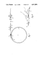
- FIG. 1 illustrates a plan view of the guidewire system generally
- FIG. 2 schematically illustrates a close up view of the guidewire aperture operated by hand
- FIG. 3 illustrates a plan view of an alternative embodiment where the aperture is located in the guidewire straightener
- FIG. 4 illustrates a perspective view of a guidewire advancement system using a slidable bar
- FIG. 5 illustrates a perspective view of a guidewire advancement system using rollers
- FIG. 6 is a magnified cross-sectional view illustrating the use of an external monitor that displays an internally generated electrical signal transmitted along the guidewire that is employed in determining the position of the guidewire.
- FIG. 1 A preferred embodiment of the guidewire advancement system 10 is illustrated in FIG. 1.
- a flexible hollow tube 11 can be disposed in the shape of a curve or loop(s) as depicted to facilitate ease of operation.
- a guidewire 12 of standard coiled spring design is slidably inserted into tube 11.
- the guidewire 12 can enter or exit tube 11 through either of the two open ends 17 and 18.
- the guidewire 12 is inserted into a vein or artery through a needle, or canal or cavity by a cannula 19.
- One end of the guidewire 12 can be formed in the shape of a flexible "J" 13.
- the "J” 13 may be straightened by pulling the end of the guidewire bearing the “J” back into the straightening element 14.
- the straightener 14 has a narrow hollow tube to which the "J" must conform upon entry therein.
- the straightener 14 is attached to tube 11 by inserting a small diameter portion 20 of straightener 14 into the port 17.
- the outer diameter of portion 20 is chosen so that it fits snugly into the hollow tube 11 at 17.
- the purpose of the "J” 13 is to permit the guidewire operator to more precisely direct the insertion of the guidewire to the precise arterial location desired.
- the operator using the tension in the straightened "J” to return to its preferred shape, can direct the guidewire down the desired artery path. Simply by rotating the guidewire within the cannula 19, the "J" 13 will be redirected as desired.
- the present invention claims the use of apertures 15 and 16 located adjacent the two end ports 17 and 18. These apertures provide access to the guidewires 12 so that it may be inserted into the bloodstream without being first removed from its storage tube 11 or jacket.
- the apertures 15 and 16 permit the use of the guidewire to be confined within the sterile field thereby substantially reducing the risk of unnecessary infection.
- FIG. 2 illustrates how the apertured guidewire system may be operated by hand, by inserting his or her thumb into the aperture 16, the operator frictionally engages the guidewire 12, and can either advance or retract it as shown.
- This design permits one handed operation that is sensitive to guidewire placement.
- Aperture 16 may be used, as opposed to aperture 15 in FIG. 1, where the operator prefers to use the straight end 21 of the guidewire through port 18, instead of the "J" shaped end 13.
- FIG. 3 illustrates another preferred embodiment of the invention where the straightener 14 is provided with aperture 25.
- the guidewire 12 can be manipulated through aperture 25 directly adjacent the guidewire exit point 22, instead of further back along the tube 11 at aperture 15 in FIG. 1.
- the apertures 15 and 16 can be enclosed with an element 30 as illustrated in FIGS. 4 and 5.
- the element 30 is used to hold the two ends of the tube 11 in the shape of a loop as shown in FIG. 1.
- the two ends of tube 11 are both snapped into the two parallel partially open tubes 33 extending through element 30 such that the apertures 15 and 16 (not shown) are completely enclosed.
- a rectangular opening 31 can be made in the element 30 opposite the apertures (not shown) in tube 11.
- a slidable cam or bar 32 may be fitted into opening 31 that can be manually depressed to frictionally engage the guidewire.
- the guidewire 12 By positioning the cam 32 at one end of the opening 31, the guidewire 12 may be advanced through the tube 11 in one direction.
- the operator slides the cam 32 to the other end of the opening 31, releasing the cam 32 from its depressed position, moving the cam 32 back to its position at the opposite end of the opening 31, and then repeating this sequence of steps until the guidewire is in the desired location.
- FIG. 5 illustrates a further embodiment of the invention in which a number of rollers 35 may be depressed to engage the guidewire 12 through an enclosed aperture in tube 11. These rollers frictionally engage the guidewire 12 such that their manually actuated rotation causes the guidewire to be pushed through tube 11 for insertion into the artery.
- Both the cam 32 of FIG. 4 and the rollers 35 of FIG. 5 may be held within member 30 by resilient means which lift the cam 32 or rollers 35 off of the guidewire 12 when not manually depressed against it by the operator.
- This resilient means renders the cam 32 or rollers 35 easier to cycle a number of times to fully extend the guidewire.
- FIG. 6 Another preferred embodiment is illustrated in the magnified cross sectional view of FIG. 6.
- a conductive guidewire 12 is displaceable through tubing 11, that is held by a housing 30.
- a slideable bar 32 is configured to move back and forth within an opening 31.
- the bar 32 is supported by a track 43.
- a lower portion of the track 43 incorporates a conductive lining 44 in conductive contact with a conductive pad 40 mounted on the underside of bar 32.
- the track 43 and attached lining 44 are flexible thereby permitting the bar 32 to be depressed manually by the operator such that the pad 40 comes in contact with the guidewire through aperture 15 of tube 11.
- the lining 44 is in conductive contact with an outlet 42 by wire 41.
- the outlet 42 is mated with an external plug 45 connected to an external monitor 46.
- the electrical signal generated by an internal organ such as the human heart transmits a signal through the guidewire 12 to pad 40 when the bar 32 is depressed.
- This signal is transmitted through the distal tip of the guidewire that has been inserted into a bodily canal or artery to determine the location of the distal tip within the body being catheterized. As the tip approaches the heart muscle, it transmits the electrical current generated about the heart along the guidewire through the engaging means of the housing to be displayed by the monitor 46.
- This system provides for a more precise positioning of the guidewire as well as the catheter while at the same time providing for the sterile insertion of the guidewire.
Abstract
Description
Claims (4)
Priority Applications (8)
| Application Number | Priority Date | Filing Date | Title |
|---|---|---|---|
| US07/372,047 US4917094A (en) | 1987-10-28 | 1989-06-27 | Guidewire advancement system |
| US07/788,049 US5273042A (en) | 1987-10-28 | 1991-11-05 | Guidewire advancement method |
| US07/857,677 US5186179A (en) | 1987-10-28 | 1992-03-25 | Guidewire advancement system |
| US08/221,083 US5448993A (en) | 1987-10-28 | 1994-03-31 | Guidewire advancement system |
| US08/233,732 US5438993A (en) | 1987-10-28 | 1994-04-26 | Guidewire advancement system |
| US08/455,698 US5810012A (en) | 1987-10-28 | 1995-05-31 | Guidewire advancement system |
| US09/069,431 US6011988A (en) | 1987-10-28 | 1998-04-29 | Guidewire advancement system |
| US09/408,383 US6477402B1 (en) | 1987-10-28 | 1999-09-29 | Guidewire advancement system |
Applications Claiming Priority (2)
| Application Number | Priority Date | Filing Date | Title |
|---|---|---|---|
| US07/114,451 US4860757A (en) | 1987-10-28 | 1987-10-28 | Guidewire advancement system |
| US07/372,047 US4917094A (en) | 1987-10-28 | 1989-06-27 | Guidewire advancement system |
Related Parent Applications (1)
| Application Number | Title | Priority Date | Filing Date |
|---|---|---|---|
| US07/114,451 Division US4860757A (en) | 1987-10-28 | 1987-10-28 | Guidewire advancement system |
Related Child Applications (2)
| Application Number | Title | Priority Date | Filing Date |
|---|---|---|---|
| US50950090A Continuation-In-Part | 1987-10-28 | 1990-04-13 | |
| US07/509,900 Continuation-In-Part US5067701A (en) | 1990-04-16 | 1990-04-16 | Multiple bill escrow mechanism |
Publications (1)
| Publication Number | Publication Date |
|---|---|
| US4917094A true US4917094A (en) | 1990-04-17 |
Family
ID=26812207
Family Applications (1)
| Application Number | Title | Priority Date | Filing Date |
|---|---|---|---|
| US07/372,047 Expired - Lifetime US4917094A (en) | 1987-10-28 | 1989-06-27 | Guidewire advancement system |
Country Status (1)
| Country | Link |
|---|---|
| US (1) | US4917094A (en) |
Cited By (51)
| Publication number | Priority date | Publication date | Assignee | Title |
|---|---|---|---|---|
| US5113872A (en) * | 1990-04-18 | 1992-05-19 | Cordis Corporation | Guidewire extension system with connectors |
| US5117838A (en) * | 1990-04-18 | 1992-06-02 | Cordis Corporation | Rotating guidewire extension system |
| US5186179A (en) * | 1987-10-28 | 1993-02-16 | Medical Parameters, Inc. | Guidewire advancement system |
| WO1993014803A1 (en) * | 1992-01-30 | 1993-08-05 | Intravascular Research Limited | Guide wire for a catheter with position indicating means |
| US5243995A (en) * | 1990-11-21 | 1993-09-14 | B. Braun Melsungen Ag | Guide probe and clamping bushing for ecg controlled positioning |
| US5263938A (en) * | 1992-01-28 | 1993-11-23 | Becton, Dickinson And Company | Guidewire introducer assembly |
| US5275151A (en) * | 1991-12-11 | 1994-01-04 | Clarus Medical Systems, Inc. | Handle for deflectable catheter |
| US5275173A (en) * | 1991-08-26 | 1994-01-04 | Target Therapeutics, Inc. | Extendable guidewire assembly |
| US5282479A (en) * | 1992-10-13 | 1994-02-01 | Boc Health Care, Inc. | Guidewire introducer with guidewire grasp and release means |
| US5334153A (en) * | 1992-10-07 | 1994-08-02 | C. R. Bard, Inc. | Catheter purge apparatus and method of use |
| US5366444A (en) * | 1993-07-06 | 1994-11-22 | Med-Pro Design, Inc. | Hand operated guide wire advancement device |
| US5372592A (en) * | 1992-06-22 | 1994-12-13 | C. R. Bard, Inc. | Method and device for preparing catheters prior to use |
| US5375596A (en) * | 1992-09-29 | 1994-12-27 | Hdc Corporation | Method and apparatus for determining the position of catheters, tubes, placement guidewires and implantable ports within biological tissue |
| US5386828A (en) * | 1991-12-23 | 1995-02-07 | Sims Deltec, Inc. | Guide wire apparatus with location sensing member |
| US5415177A (en) * | 1992-12-31 | 1995-05-16 | Zadini; Filiberto P. | Automatic guide wire placement device for intravascular catheters |
| US5448993A (en) * | 1987-10-28 | 1995-09-12 | Medical Parameters, Inc. | Guidewire advancement system |
| US5454785A (en) * | 1993-04-12 | 1995-10-03 | C. R. Bard, Inc. | Method of withdrawing and exchanging catheters |
| US5462527A (en) * | 1993-06-29 | 1995-10-31 | C.R. Bard, Inc. | Actuator for use with steerable catheter |
| US5634475A (en) * | 1994-09-01 | 1997-06-03 | Datascope Investment Corp. | Guidewire delivery assist device and system |
| US5645065A (en) * | 1991-09-04 | 1997-07-08 | Navion Biomedical Corporation | Catheter depth, position and orientation location system |
| US5669878A (en) * | 1992-01-30 | 1997-09-23 | Intravascular Research Limited | Guide wire for a catheter with position indicating means |
| US5715817A (en) * | 1993-06-29 | 1998-02-10 | C.R. Bard, Inc. | Bidirectional steering catheter |
| US5797858A (en) * | 1997-03-14 | 1998-08-25 | Hewlett-Packard Company | Spooling pullback for catheter imaging and therapy cores |
| US5827202A (en) * | 1996-06-10 | 1998-10-27 | Baxter International Inc. | Guide wire dispenser apparatus and method |
| US5843002A (en) * | 1996-06-10 | 1998-12-01 | Baxter International Inc. | Guide wire dispenser apparatus and method |
| US5868755A (en) * | 1997-01-16 | 1999-02-09 | Atrion Medical Products, Inc. | Sheath retractor mechanism and method |
| US6086008A (en) * | 1997-12-22 | 2000-07-11 | Deka Products Limited Partnership | Apparatus and method for permitting introduction and withdrawal of a catheter |
| US6096022A (en) * | 1995-08-31 | 2000-08-01 | Target Therapeutics Inc. | Bi-directional catheter |
| US6190333B1 (en) | 1999-10-15 | 2001-02-20 | Mark Ii Research And Development Corp. | Threader device for threading a guidewire into a catheter |
| US6231564B1 (en) | 1995-09-29 | 2001-05-15 | Medtronic Ave, Inc. | Storable guidewire system |
| US6551281B1 (en) | 2000-01-13 | 2003-04-22 | Medical Components, Inc. | Guide wire advancer and assembly and method for advancing a guide wire |
| US20040082880A1 (en) * | 2001-08-15 | 2004-04-29 | Heh Kok Boon | Roller wheel assisted guidewire advancer |
| US20060253048A1 (en) * | 2005-05-05 | 2006-11-09 | Abbott Laboratories | Guidewire loader apparatus and method |
| US20090277988A1 (en) * | 2008-05-07 | 2009-11-12 | Matthias Hernik | Device for holding an elastically deformable winding article and apparatus for winding the winding article into the device |
| US20100152613A1 (en) * | 2008-12-11 | 2010-06-17 | Shawn Ryan | Clip for handling an endoscopic device |
| US20100212305A1 (en) * | 2009-02-26 | 2010-08-26 | Barnes Group Inc. | Counterbalancing arrangement |
| US7803142B2 (en) | 2005-02-02 | 2010-09-28 | Summit Access Llc | Microtaper needle and method of use |
| US7993329B2 (en) | 2002-08-13 | 2011-08-09 | Cook Medical Technologies Llc | ERCP catheter with a removable handle for lithotriptor compatible basket |
| WO2013142386A1 (en) * | 2012-03-18 | 2013-09-26 | Avneri Itzhak | Devices and methods for endovascular access and therapy |
| US8764730B2 (en) | 2007-06-26 | 2014-07-01 | Roxwood Medical, Inc. | Catheter apparatus and methods for treating vasculatures |
| US9011351B2 (en) | 2010-09-24 | 2015-04-21 | Covidien Lp | Guidewire insertion aid |
| US9126020B2 (en) | 2007-06-26 | 2015-09-08 | Roxwood Medical, Inc. | Catheter apparatus with telescoping lumen catheters and its use in methods for treating vasculatures |
| US9125683B2 (en) | 2007-06-26 | 2015-09-08 | Roxwood Medical Inc. | Method and apparatus for placing a catheter within a vasculature |
| US9358037B2 (en) | 2007-06-26 | 2016-06-07 | Roxwood Medical, Inc. | Method and apparatus for centering a microcatheter within a vasculature |
| US9439653B2 (en) | 2011-12-07 | 2016-09-13 | Traumatek Solutions B.V. | Devices and methods for endovascular access and therapy |
| US10118020B2 (en) | 2011-12-07 | 2018-11-06 | Traumatek Solutions B.V. | Devices and methods for endovascular access and therapy |
| US10426510B2 (en) | 2012-10-22 | 2019-10-01 | Roxwood Medical, Inc. | Method and apparatus for centering a microcatheter within a vasculature |
| US10596354B2 (en) | 2015-09-25 | 2020-03-24 | Mark Taber | Guide wires, catheters, and guide wire catheter systems and methods |
| US10967153B2 (en) | 2007-02-08 | 2021-04-06 | C. R. Bard, Inc. | Shape memory medical device and methods of use |
| US10987488B2 (en) | 2015-06-23 | 2021-04-27 | Traumatek Solutions, B.V. | Vessel cannulation device and method of use |
| US11712541B2 (en) * | 2012-12-31 | 2023-08-01 | Clearstream Technologies Limited | Counting apparatus for use in interventional procedures |
Citations (10)
| Publication number | Priority date | Publication date | Assignee | Title |
|---|---|---|---|---|
| US3561445A (en) * | 1968-07-03 | 1971-02-09 | Abbott Lab | Catheter placement unit |
| US3995628A (en) * | 1975-04-25 | 1976-12-07 | Travenol Laboratories, Inc. | Catheter insertion device |
| US4003369A (en) * | 1975-04-22 | 1977-01-18 | Medrad, Inc. | Angiographic guidewire with safety core wire |
| US4160451A (en) * | 1977-11-25 | 1979-07-10 | Abbott Laboratories | Unidirectional catheter placement unit |
| US4342313A (en) * | 1981-02-23 | 1982-08-03 | Abbott Laboratories | Catheter insertion device |
| US4397091A (en) * | 1980-10-22 | 1983-08-09 | Bengt Gustavsson | Dispensing container for venus catheters |
| US4425908A (en) * | 1981-10-22 | 1984-01-17 | Beth Israel Hospital | Blood clot filter |
| US4534363A (en) * | 1982-04-29 | 1985-08-13 | Cordis Corporation | Coating for angiographic guidewire |
| US4650472A (en) * | 1985-08-30 | 1987-03-17 | Cook, Incorporated | Apparatus and method for effecting percutaneous catheterization of a blood vessel using a small gauge introducer needle |
| US4676249A (en) * | 1986-05-19 | 1987-06-30 | Cordis Corporation | Multi-mode guidewire |
-
1989
- 1989-06-27 US US07/372,047 patent/US4917094A/en not_active Expired - Lifetime
Patent Citations (11)
| Publication number | Priority date | Publication date | Assignee | Title |
|---|---|---|---|---|
| US3561445A (en) * | 1968-07-03 | 1971-02-09 | Abbott Lab | Catheter placement unit |
| US4003369A (en) * | 1975-04-22 | 1977-01-18 | Medrad, Inc. | Angiographic guidewire with safety core wire |
| US4080706A (en) * | 1975-04-22 | 1978-03-28 | Medrad, Inc. | Method of manufacturing catheter guidewire |
| US3995628A (en) * | 1975-04-25 | 1976-12-07 | Travenol Laboratories, Inc. | Catheter insertion device |
| US4160451A (en) * | 1977-11-25 | 1979-07-10 | Abbott Laboratories | Unidirectional catheter placement unit |
| US4397091A (en) * | 1980-10-22 | 1983-08-09 | Bengt Gustavsson | Dispensing container for venus catheters |
| US4342313A (en) * | 1981-02-23 | 1982-08-03 | Abbott Laboratories | Catheter insertion device |
| US4425908A (en) * | 1981-10-22 | 1984-01-17 | Beth Israel Hospital | Blood clot filter |
| US4534363A (en) * | 1982-04-29 | 1985-08-13 | Cordis Corporation | Coating for angiographic guidewire |
| US4650472A (en) * | 1985-08-30 | 1987-03-17 | Cook, Incorporated | Apparatus and method for effecting percutaneous catheterization of a blood vessel using a small gauge introducer needle |
| US4676249A (en) * | 1986-05-19 | 1987-06-30 | Cordis Corporation | Multi-mode guidewire |
Non-Patent Citations (1)
| Title |
|---|
| The Literature of Arrow International, 1986. * |
Cited By (64)
| Publication number | Priority date | Publication date | Assignee | Title |
|---|---|---|---|---|
| US5186179A (en) * | 1987-10-28 | 1993-02-16 | Medical Parameters, Inc. | Guidewire advancement system |
| US5448993A (en) * | 1987-10-28 | 1995-09-12 | Medical Parameters, Inc. | Guidewire advancement system |
| US6477402B1 (en) | 1987-10-28 | 2002-11-05 | Arrow International Investment Corp. | Guidewire advancement system |
| US6011988A (en) * | 1987-10-28 | 2000-01-04 | Arrow International Investment | Guidewire advancement system |
| US5810012A (en) * | 1987-10-28 | 1998-09-22 | Medical Parameters, Inc. | Guidewire advancement system |
| US5113872A (en) * | 1990-04-18 | 1992-05-19 | Cordis Corporation | Guidewire extension system with connectors |
| US5117838A (en) * | 1990-04-18 | 1992-06-02 | Cordis Corporation | Rotating guidewire extension system |
| US5243995A (en) * | 1990-11-21 | 1993-09-14 | B. Braun Melsungen Ag | Guide probe and clamping bushing for ecg controlled positioning |
| US5275173A (en) * | 1991-08-26 | 1994-01-04 | Target Therapeutics, Inc. | Extendable guidewire assembly |
| US5645065A (en) * | 1991-09-04 | 1997-07-08 | Navion Biomedical Corporation | Catheter depth, position and orientation location system |
| US5275151A (en) * | 1991-12-11 | 1994-01-04 | Clarus Medical Systems, Inc. | Handle for deflectable catheter |
| US5386828A (en) * | 1991-12-23 | 1995-02-07 | Sims Deltec, Inc. | Guide wire apparatus with location sensing member |
| US5263938A (en) * | 1992-01-28 | 1993-11-23 | Becton, Dickinson And Company | Guidewire introducer assembly |
| US6050958A (en) * | 1992-01-30 | 2000-04-18 | Intravascular Research Limited | Guide wire for a catheter with position indicating means |
| WO1993014803A1 (en) * | 1992-01-30 | 1993-08-05 | Intravascular Research Limited | Guide wire for a catheter with position indicating means |
| US5669878A (en) * | 1992-01-30 | 1997-09-23 | Intravascular Research Limited | Guide wire for a catheter with position indicating means |
| US5372592A (en) * | 1992-06-22 | 1994-12-13 | C. R. Bard, Inc. | Method and device for preparing catheters prior to use |
| US5375596A (en) * | 1992-09-29 | 1994-12-27 | Hdc Corporation | Method and apparatus for determining the position of catheters, tubes, placement guidewires and implantable ports within biological tissue |
| US5334153A (en) * | 1992-10-07 | 1994-08-02 | C. R. Bard, Inc. | Catheter purge apparatus and method of use |
| US5282479A (en) * | 1992-10-13 | 1994-02-01 | Boc Health Care, Inc. | Guidewire introducer with guidewire grasp and release means |
| US5415177A (en) * | 1992-12-31 | 1995-05-16 | Zadini; Filiberto P. | Automatic guide wire placement device for intravascular catheters |
| US5454785A (en) * | 1993-04-12 | 1995-10-03 | C. R. Bard, Inc. | Method of withdrawing and exchanging catheters |
| US5462527A (en) * | 1993-06-29 | 1995-10-31 | C.R. Bard, Inc. | Actuator for use with steerable catheter |
| US5715817A (en) * | 1993-06-29 | 1998-02-10 | C.R. Bard, Inc. | Bidirectional steering catheter |
| US5366444A (en) * | 1993-07-06 | 1994-11-22 | Med-Pro Design, Inc. | Hand operated guide wire advancement device |
| US5634475A (en) * | 1994-09-01 | 1997-06-03 | Datascope Investment Corp. | Guidewire delivery assist device and system |
| US6096022A (en) * | 1995-08-31 | 2000-08-01 | Target Therapeutics Inc. | Bi-directional catheter |
| US6231564B1 (en) | 1995-09-29 | 2001-05-15 | Medtronic Ave, Inc. | Storable guidewire system |
| US5843002A (en) * | 1996-06-10 | 1998-12-01 | Baxter International Inc. | Guide wire dispenser apparatus and method |
| US5827202A (en) * | 1996-06-10 | 1998-10-27 | Baxter International Inc. | Guide wire dispenser apparatus and method |
| US5868755A (en) * | 1997-01-16 | 1999-02-09 | Atrion Medical Products, Inc. | Sheath retractor mechanism and method |
| US5797858A (en) * | 1997-03-14 | 1998-08-25 | Hewlett-Packard Company | Spooling pullback for catheter imaging and therapy cores |
| US6086008A (en) * | 1997-12-22 | 2000-07-11 | Deka Products Limited Partnership | Apparatus and method for permitting introduction and withdrawal of a catheter |
| US6190333B1 (en) | 1999-10-15 | 2001-02-20 | Mark Ii Research And Development Corp. | Threader device for threading a guidewire into a catheter |
| US6551281B1 (en) | 2000-01-13 | 2003-04-22 | Medical Components, Inc. | Guide wire advancer and assembly and method for advancing a guide wire |
| US20040082880A1 (en) * | 2001-08-15 | 2004-04-29 | Heh Kok Boon | Roller wheel assisted guidewire advancer |
| US7993329B2 (en) | 2002-08-13 | 2011-08-09 | Cook Medical Technologies Llc | ERCP catheter with a removable handle for lithotriptor compatible basket |
| US7803142B2 (en) | 2005-02-02 | 2010-09-28 | Summit Access Llc | Microtaper needle and method of use |
| US20060253048A1 (en) * | 2005-05-05 | 2006-11-09 | Abbott Laboratories | Guidewire loader apparatus and method |
| US7951092B2 (en) * | 2005-05-05 | 2011-05-31 | Abbott Cardiovascular Systems Inc. | Guidewire loader apparatus and method |
| US10967153B2 (en) | 2007-02-08 | 2021-04-06 | C. R. Bard, Inc. | Shape memory medical device and methods of use |
| US11065028B2 (en) | 2007-06-26 | 2021-07-20 | Roxwood Medical Inc. | Method and apparatus for placing a catheter within a vasculature |
| US9358037B2 (en) | 2007-06-26 | 2016-06-07 | Roxwood Medical, Inc. | Method and apparatus for centering a microcatheter within a vasculature |
| US10471234B2 (en) | 2007-06-26 | 2019-11-12 | Roxwood Medical, Inc. | Catheter apparatus and methods for treating vasculatures |
| US10130795B2 (en) | 2007-06-26 | 2018-11-20 | Roxwood Medical Inc. | Catheter apparatus with telescoping lumen catheters and its use in methods for treating vasculatures |
| US8764730B2 (en) | 2007-06-26 | 2014-07-01 | Roxwood Medical, Inc. | Catheter apparatus and methods for treating vasculatures |
| US10130385B2 (en) | 2007-06-26 | 2018-11-20 | Roxwood Medical Inc. | Method and apparatus for placing a catheter within a vasculature |
| US9126020B2 (en) | 2007-06-26 | 2015-09-08 | Roxwood Medical, Inc. | Catheter apparatus with telescoping lumen catheters and its use in methods for treating vasculatures |
| US9125683B2 (en) | 2007-06-26 | 2015-09-08 | Roxwood Medical Inc. | Method and apparatus for placing a catheter within a vasculature |
| US20090277988A1 (en) * | 2008-05-07 | 2009-11-12 | Matthias Hernik | Device for holding an elastically deformable winding article and apparatus for winding the winding article into the device |
| US8651412B2 (en) * | 2008-05-07 | 2014-02-18 | Endox Feinwerktechnik Gmbh | Device for holding an elastically deformable winding article and apparatus for winding the winding article into the device |
| US20100152613A1 (en) * | 2008-12-11 | 2010-06-17 | Shawn Ryan | Clip for handling an endoscopic device |
| US20100212305A1 (en) * | 2009-02-26 | 2010-08-26 | Barnes Group Inc. | Counterbalancing arrangement |
| US9545504B2 (en) | 2010-09-24 | 2017-01-17 | Covidien Lp | Guidewire insertion aid |
| US9011351B2 (en) | 2010-09-24 | 2015-04-21 | Covidien Lp | Guidewire insertion aid |
| US10124144B2 (en) | 2011-12-07 | 2018-11-13 | Traumatek Solutions, B.V. | Devices and methods for endovascular access and therapy |
| US9439653B2 (en) | 2011-12-07 | 2016-09-13 | Traumatek Solutions B.V. | Devices and methods for endovascular access and therapy |
| US10118020B2 (en) | 2011-12-07 | 2018-11-06 | Traumatek Solutions B.V. | Devices and methods for endovascular access and therapy |
| US11154690B2 (en) | 2011-12-07 | 2021-10-26 | Traumatek Solutions, B.V. | Devices and methods for endovascular access and therapy |
| WO2013142386A1 (en) * | 2012-03-18 | 2013-09-26 | Avneri Itzhak | Devices and methods for endovascular access and therapy |
| US10426510B2 (en) | 2012-10-22 | 2019-10-01 | Roxwood Medical, Inc. | Method and apparatus for centering a microcatheter within a vasculature |
| US11712541B2 (en) * | 2012-12-31 | 2023-08-01 | Clearstream Technologies Limited | Counting apparatus for use in interventional procedures |
| US10987488B2 (en) | 2015-06-23 | 2021-04-27 | Traumatek Solutions, B.V. | Vessel cannulation device and method of use |
| US10596354B2 (en) | 2015-09-25 | 2020-03-24 | Mark Taber | Guide wires, catheters, and guide wire catheter systems and methods |
Similar Documents
| Publication | Publication Date | Title |
|---|---|---|
| US4917094A (en) | Guidewire advancement system | |
| US4860757A (en) | Guidewire advancement system | |
| US5448993A (en) | Guidewire advancement system | |
| US11213362B2 (en) | Device for automatically inserting and manipulating a medical tool into and within a bodily lumen | |
| US6626869B1 (en) | Guide wire introducer | |
| US3521620A (en) | Vascular coil spring guide with bendable tip | |
| US5186179A (en) | Guidewire advancement system | |
| EP0132387B1 (en) | Catheter wire guide with movable mandril | |
| US5242428A (en) | Apparatus for wetting hydrophilic-coated guide wires and catheters | |
| US5507300A (en) | Guide wire feeding device | |
| US10617846B2 (en) | Guidewire advancing device and method | |
| JP4368470B2 (en) | Catheter with two-way control handle | |
| US5484419A (en) | Hand-held device for feeding a spring wire guide | |
| EP0554754B1 (en) | Guidewire introducer assembly | |
| US20050277988A1 (en) | Energizer for vascular guidewire | |
| US20090036840A1 (en) | Atraumatic ball tip and side wall opening | |
| AU5691398A (en) | Guide wire dispenser apparatus | |
| JP2022125001A (en) | Insertion device for one-handed insertion of guide wire into lumen of vessel/cavity | |
| WO1998019720A2 (en) | Guide wire placement apparatus | |
| WO2022132920A1 (en) | Wire and catheter placement device | |
| Katsinelos et al. | The use of guidewires in diagnostic and therapeutic endoscopic retrograde cholangiopancreatography (ERCP) | |
| JPH02206417A (en) | Flexible tube for insertion in body cavity |
Legal Events
| Date | Code | Title | Description |
|---|---|---|---|
| STCF | Information on status: patent grant |
Free format text: PATENTED CASE |
|
| FPAY | Fee payment |
Year of fee payment: 4 |
|
| FPAY | Fee payment |
Year of fee payment: 8 |
|
| AS | Assignment |
Owner name: ARROW INTERNATIONAL, INC., PENNSYLVANIA Free format text: ASSIGNMENT OF ASSIGNORS INTEREST;ASSIGNOR:MEDICAL PARAMETERS, INC.;REEL/FRAME:009605/0882 Effective date: 19980804 Owner name: ARROW INTERNATIONAL INVESTMENT CORP., DELAWARE Free format text: ASSIGNMENT OF ASSIGNORS INTEREST;ASSIGNOR:ARROW INTERNATIONAL, INC.;REEL/FRAME:009605/0947 Effective date: 19980805 |
|
| FEPP | Fee payment procedure |
Free format text: PAT HOLDER NO LONGER CLAIMS SMALL ENTITY STATUS, ENTITY STATUS SET TO UNDISCOUNTED (ORIGINAL EVENT CODE: STOL); ENTITY STATUS OF PATENT OWNER: LARGE ENTITY |
|
| REFU | Refund |
Free format text: REFUND - PAYMENT OF MAINTENANCE FEE, 12TH YR, SMALL ENTITY (ORIGINAL EVENT CODE: R285); ENTITY STATUS OF PATENT OWNER: LARGE ENTITY |
|
| FPAY | Fee payment |
Year of fee payment: 12 |
|
| SULP | Surcharge for late payment |
Year of fee payment: 11 |